Table of Contents
Advertisement
Available languages
Available languages
Quick Links
Advertisement
Table of Contents

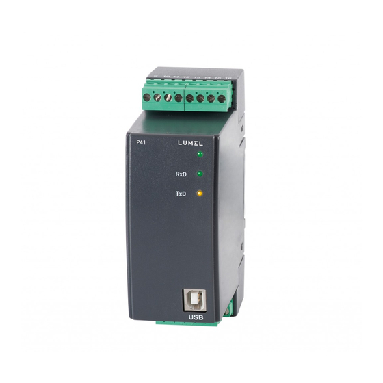
Summary of Contents for Lumel P41
- Page 1 PRZETWORNIK PARAMETRÓW SIECI TRANSDUCER OF NETWORK PARAMETERS INSTRUKCJA OBSŁUGI SZYBKI START USER’S MANUAL QUICK START Zeskanuj mnie Zeskanuj kod Scan the code Pełna wersja instrukcji dostępna na Full version of user’s manual available at www.lumel.com.pl...
- Page 2 • zdjęcie obudowy przetwornika w trakcie trwania umowy gwarancyjnej powoduje jej unieważnienie. 2. MONTAŻ 2.1. Sposób mocowania. Przetwornik P41 jest przeznaczony do mocowania na wsporniku szynowym 35 mm wg PN-EN 60715. Gabaryty i sposób mocowania ilustruje rysunek 1.
- Page 3 Rys.1. Gabaryty i sposób mocowania przetwornika. 2.2. Schematy podłączeń zewnętrznych schematy podłączeń przedstawiono na rys. 2, na stronie 14.
- Page 4 3.3 Konfi guracja przetwornika za pomocą programu econ do konfi guracji przetwornika p41 przeznaczone jest opro- gramowanie econ. przetwornik należy połączyć z komputerem pc poprzez konwerter pd10, jeżeli komunikacja wykonywana będzie przez złącze rs485, lub bezpośrednio poprzez złącze UsB (więcej: pełna...
-
Page 5: Dane Techniczne
4. DANE TECHNICZNE Zakresy pomiarowe i dopuszczalne błędy podstawowe przetwar- zania (tablica 1) tablica 1 Wielkość Błąd Zakres pomiarowy mierzona podstawowy prąd 1 a ~ 0,005...1,200 a~ ±0,2% 5 a ~ 0,025...6,000 a~ napięcie l-n 100 V~ 1...120 V ±0,2% 400 V~ 4...480 V częstotliwość... - Page 6 Przekładnia przekładnika napięciowego Ku: 0,1 .. 4000,0 Przekładnia przekładnika prądowego Ki: 1 .. 10000 Stopień ochrony zapewniany przez obudowę: dla obudowy: ip 40 dla zacisków: ip 10 Masa: 0,2 kg Wymiary: 40 x 120 x 100 mm Mocowanie: na wsporniku szynowym 35 mm Warunki odniesienia i znamionowe warunki użytkowania - napięcie zasilania: 85..253 V a.c.
- Page 7 * * numerację wykonania ustali producent PRZYKŁAD ZAMÓWIENIA: kod P41-100P0 oznacza wykonanie przetwornika na napięcie zasilające 85..253 V a.c.; 90..300 V d.c. Wykonanie standardowe, instrukcja po polsku, bez wymagań dodatkowych.
-
Page 8: Basic Requirements, Operational Safety
2. INSTALLATION 2.1. Mounting method p41 transducer should be mounted on a 35 mm rail bracket according to en 60715. dimensions and method of mounting hare shown in fi gure 1. - Page 9 Fig.1. Overall dimensions and method of mounting the transducer. 2.2. External connections diagrams connection diagrams are presented on fi g.2, on page 14.
-
Page 10: Operation
3.3 transducer confi guration using econ econ program is destined for the confi guration of the p41 transducer. the transducer ought to be connected to pc using a pd10 converter (if the communication will be carried out through rs485) or directly through UsB (For details - see full version of user’s manual -... -
Page 11: Technical Data
4. TECHNICAL DATA Measuring ranges and admissible basic errors (table 1) table 1 Basic Measured quantity Measuring range error current 1 a ~ 0.005...1.200 a~ ±0.2% 5 a ~ 0.025...6.000 a~ Voltage l-n 100 V~ 1...120.0 V~ ±0.2% 400 V~ 4...480 V~ Frequency 45.0...66.0...100 Hz... - Page 12 Ratio of the Voltage transformer Ku: 0.1 .. 4000.0 Ratio of the Current transformer Ki: 1 .. 10000 Protection degree ensured by the housing: for the housing ip 40 for terminals ip 10 Weight: 0.2 kg Dimensions: 40 x 120 x 100 mm Fixing Way: on a 35 mm din rail Reference and rated operating conditions - supply voltage: 85..253 V a.c.
-
Page 13: Ordering Code
Electromagnetic compatibility: - noise immunity acc. to en 61000-6-2 - noise emission acc. to EN 61000-6-4 Safety requirements: according to EN 61010-1 • isolation between circuits: basic, • installation category iii, • pollution level 2, • maximal phase-to-earth voltage: - for supply and measurement circuits 300 V - for other circuits 50 V •... - Page 14 schematy podłączeń electrical connections wyjście zasilanie analogowe wyjście zasilanie analogowe pomiar bez pomiar bezp L2 lub N L2 lub N L2 or N pomiar poś pomiar bezpośredni pomiar pośr direct measurement...
- Page 15 L2 lub N L2 or N pomiar L2 lub N L2 or N pomiar pośredni indirect measurement Rys. 2. Podłączenia przetwornika. Fig. 2. Transducer connections...
- Page 16 LUMEL S.A. ul. Sulechowska 1, 65-022 Zielona Góra, Poland tel.: +48 68 45 75 100, fax +48 68 45 75 508 www.lumel.com.pl Informacja techniczna: tel.: (68) 45 75 306, 45 75 180, 45 75 260 e-mail: sprzedaz@lumel.com.pl Realizacja zamówień: tel.: (68) 45 75 207, 45 75 209, 45 75 218, 45 75 341 fax.: (68) 32 55 650...


Need help?
Do you have a question about the P41 and is the answer not in the manual?
Questions and answers