
Related Manuals for Lumel P21Z Series


Summary of Contents for Lumel P21Z Series
- Page 1 PROGRAMMABLE TRANSDUCER OF AC CURRENT AND AC VOLTAGE SIGNALS AND FREQUENCY P21Z TYPE USER’S MANUAL...
-
Page 3: Table Of Contents
Contents 1 . application.................5 2. transducer set ..............5 3. Basic requirements and operational safety ......6 4. installation ...............7 4.1 mounting ..............7 4.2 diagrams of external connections ........8 5. operation ................. 10 5.1 transducer configuration with econ software ......12 5.2 register map (for version with rs-485) ....... 12 5.3 manufacturer’s parameters ..........16 6. t echnical data ..............18 7. ordering code ..............21... -
Page 5: Application
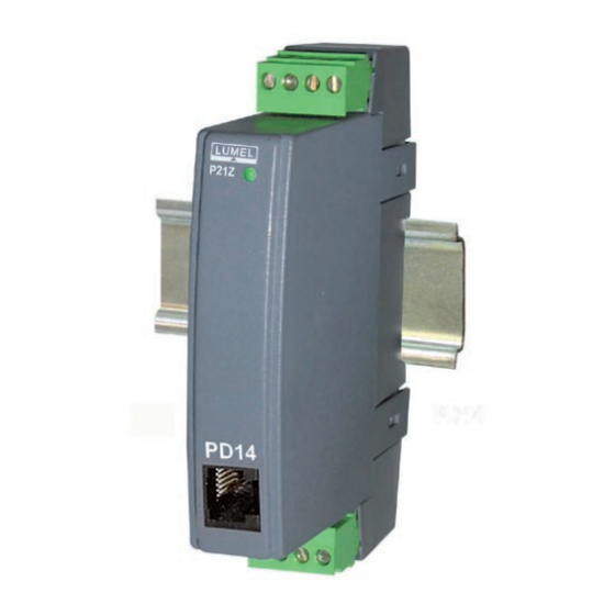
1. APPLICATION P21Z transducers are used for converting one parameter: a.c. voltage, a.c. current or frequency into a standardized direct current signal, direct voltage signal or digital signal available through RS485 interface. The transducers are designed also to work with voltage and current transformers. P21Z transducer may be configured with PD14 pro- grammer. -
Page 6: Basic Requirements And Operational Safety
3. BASIC RequIRemeNTS AND OPeRATIONAL SAfeTy The operational safety of the transducer is compliant with the requirements of eN 61010-1 standard The meaning of the following symbol: - Attention! Danger! Observations Concerning the Operational Safety: • All operations concerning transport, installation, and com- missioning as well as maintenance, must be carried out by qualified, skilled personnel, and national regulations for the prevention of accidents must be observed. -
Page 7: Installation
4. INSTALLATION 4.1 mounting P21Z transducers designed mounting on a 35 mm according to PN-eN 60715. Dimensions and moun- ting method are presented in fig. 1. Connection of PD14 programmer Fig 1. Dimensions and mounting of the transducer. -
Page 8: Diagrams Of External Connections
4.2 Diagrams of external connections The transmitter transducer has a detachable terminal strip with screw terminals that enable user to connect external power supply and output cables with cross section up to 2.5 mm . Input signals shall be connected with wires of a maximum diameter of 1.5 mm to fixed screw terminals. - Page 9 Direct measurement Indirect measurement of frequency of frequency with voltage transformer Fig. 2. Electric connections of P21Z inputs. a) analog b) interface output RS-485 supply analog supply output Fig. 3. Electric connections of P21Z power supply and output.
-
Page 10: Operation
5. OPeRATION After the transducer is switched on, its Status LeD should illuminate in red (transducer initialization), then it should turn green (normal operation). Status LeD of the transducer: • when illuminated in green – normal operation; • when illuminated in red – incorrect operational parameters;... - Page 11 Table 1 Number Refreshing processed value Averaging of averaged (time of one time measurements measurement) 0.5 s every 0.5 s every 0.5 s every 0.5 s every 0.5 s 10 s every 0.5 s 15 s every 0.5 s 30 s every 0.5 s 1 min every 0.6 s...
-
Page 12: Transducer Configuration With Econ Software
5.1 Transducer configuration with eCon software Configuration of P21Z transducers is performed with eCon software available free of charge at www.lumel.com.pl. Detailed description of parameter configuration is presented in the manual for Transducer configuration with eCon software. Transducers with RS-485 interface may be configured directly via the interface. - Page 13 4005 0..2 Transmission mode: 0->4800, 1->9600, 2->19200 4006 0, 1 Change mODBuS transmission parame- ters: 1 - change 4007 0...65535 Status 4008 reserved 4009 0..65535 reserved 4010 0..65535 reserved 4011 0..65535 Software version Status register description XXXX bity Bit-15 Uncalibrated transducer 0 –...
- Page 14 Bit-12 Averaging 0 – full measurement averaging time expired 1 – full measurement averaging time not expired Bits- 11 – 7 Reserved Bits - 6 - 3 Measuring input Bit 6 Bit 5 Bit 4 Bit 3 Meaning reserved 100 V a.c. 250 V a.c.
- Page 15 Table 3 Regi- Regi- ster ster Description dress dress 2x16 32 bit 7200 7600 Continuous output – lower input value (x1) 7202 7601 Continuous output – upper input value (x2) 7204 7602 Continuous output – lower output value (y1) 7206 7603 Continuous output –...
-
Page 16: Manufacturer's Parameters
5.3 manufacturer’s parameters Table 4 Parameter description Range / Value Default value * Averaging time**** 0.5 s; 1 s; 3 s; 5 s; 10 s; 15 s; 30 s; 1 min; 2 min s; 5 min; 7 min; 12 min; 15 min; Continuous output: normal work, minimum normal work... - Page 17 * - depending on design **- for 4..20 mA version, overflow service is activated, minimum output value is set at 4 mA, input values: minimu and maximum are calculated according to transition data. *** - only for version with RS-485 output ****- for transducers with the input for frequency measurement, the measurement time is always 1s, regardless the values in registers 7200 and 7600.
-
Page 18: Technical Data
6. TeCHNICAL DATA Measuring ranges iNPUtS: measuring range for AC voltage (un): 0..1..100…130 V a.c. 0..2.5..250…325 V a.c. input resistance > 2 m 0..4..400…600 V a.c. measuring range for AC current (In): 0..0.01..1.0…1.3 A a.c. input resistance 10 m 10 % 0..0.05..5.0…6.3 A a.c. - Page 19 Basic conversion error (by default settings): voltage and current: 0.2% of range in the frequency range 45...65 Hz frequency: 0.02 % of range Additional errors in rated operating conditions: from ambient temperature changes (100 % of basic error/10 K) Sustained overload: 150 % un (in.
- Page 20 Galvanic isolation between: - supply – meas.input: 3.2 kV d.c. - supply – output: 2 kV d.c. - measuring input – output: 3.2 kV d.c. Ensured protection grade acc. to EN 60529: for the housing IP40 from the terminal side IP20 Dimensions: 22.5 x 100 x 120 mm...
-
Page 21: Ordering Code
7.ORDeRINg CODe Table 5 PROgRAmmABLe TRANSDuCeR Of AC CuRReNT AND AC VOLTAge P21Z - X X X XX X X input signal: 100 V a.c. 250 V a.c. 400 V a.c. 1 A a.c. 5 A a.c. frequency 20...500 Hz Output: 0...20 mA 4...20 mA... - Page 22 Order example: The code P21Z - 1 1 1 00 E 0 means: P21Z - transducer of d.c. current or d.c. voltage signals 1 - input signal: 1...100 V a.c. 1 - output signal: 0...20 mA 1 - supply voltage: 85..253 V a.c. 40..400 Hz; 90..300 V d.c. 00 - standard version E - english language 0 - without extra quality inspecti on requirements...
- Page 24 LUMEL S.A. ul. Słubicka 1, 65-127 Zielona Góra, Poland Москва, м. Авиамоторная, пр-д Завода Серп и Молот тел:+7(495)510-11-04 e-mail:zakaz@energometrika.ru web: www.energometrika.ru...
Need help?
Do you have a question about the P21Z Series and is the answer not in the manual?
Questions and answers