Table of Contents
Advertisement
Quick Links
Advertisement
Table of Contents

Related Manuals for Lumel P30P


Summary of Contents for Lumel P30P
- Page 1 TRANSDUCER OF 1-PHASE POWER NETWORK PARAMETERS P30P USER’S MANUAL...
-
Page 2: Table Of Contents
4. Installation............................. 7 4.1. Mounting............................7 4.2. External connection diagrams......................8 5. Service..............................10 5.1. Description of P30P transducer's frontal plate................10 5.2. Power-on messages........................11 5.3. Functions of the buttons....................... 11 5.3.1. Functions of single buttons....................11 5.3.2. Functions of button combinations..................12 5.3.3. - Page 3 P30P-09A User's manual 5.10.2.2. Web user selection..................... 79 5.10.3 FTP Server.......................... 80 5.10.3.1. FTP user selection...................... 81 5.10.4 Modbus TCP/IP........................81 6. Accessories............................82 7. Error codes............................82 8. Technical data............................83 12. Ordering code............................ 87...
-
Page 4: Application
User's manual 1. Application Programmable transducer P30P is suited for single-phase power line parameters measurement and converting them into standard d.c current or d.c. voltage signal. Output signal is galvanically isolated from input signal and power signal. Transducer uses 2x8 characters LCD. - Page 5 Transducer allows for the use of external transmission and measurement conversion included in the measurement and calculation of all measured values. Value upgrade time does not exceed 1 second. All values and configuration parameters are available through RS-485 and Ethernet (Modbus protocol) (option). Fig. 1 Appearance of P30P transducer different versions.
-
Page 6: Transducer Set
P30P-09A User's manual 2. Transducer set ● P30P Transducer 1 pc ● user's manual 1 pc ● warranty card 1 pc ● plug with the screw terminals 2 pc 3. Basic requirements, operational safety In the security scope, the transducer meets the requirements of the EN 61010-1 standard. -
Page 7: Installation
P30P-09A User's manual 4. Installation 4.1. Mounting The P30 transducer are designed for installation on a 35 mm rail acc. to EN 60715. Overall dimensions and mounting is shown in Figure 2. Fig. 2 Overall dimensions and mounting of the transducer. -
Page 8: External Connection Diagrams
P30P-09A User's manual 4.2. External connection diagrams... - Page 9 P30P-09A User's manual Fig.3 Wiring diagram of the P30P transducer...
-
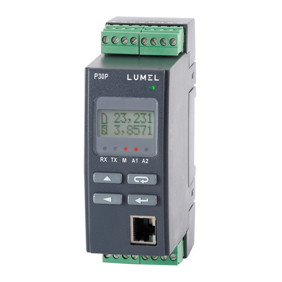
Page 10: Service
P30P-09A User's manual 5. Service 5.1. Description of P30P transducer's frontal plate Fig.4 Description of the transducer's frontal plate Note: Memory card (optional) should be inserted into the transducer with contacts on the bottom side. Description of LED indicator: RX – green LED - indicator of data receiving on RS-485 link TX –... -
Page 11: Power-On Messages
LED (power indicator) on, transducer displays the type, current software version and the serial number. If the transducer is equipped with Ethernet interface (P30P-XX2XXXXXXX), then after displaying the serial no., the device displays also the IP address saved in memory or received from DHCP server. -
Page 12: Functions Of Button Combinations
P30P-09A User's manual RS-485 interface, the link parameters: baud rate 9600 bit/s, 8N2 mode. - increase value button ● change of the displayed value, ● navigation within selected level, ● change of the selected parameter value – value increase, - digit change button ●... - Page 13 P30P-09A User's manual - holding down for approx. 1 second ● unmounts the SD/SDHC card allowing it to be safely removed – for the transducers with external SD/SDHC card slot - holding down for approx. 1 second ● forces the rewriting of the archive from internal memory to the SD/SDHC card – for the transducers with external SD/SDHC card slot ●...
-
Page 14: Programming Matrix
P30P-09A User's manual 5.3.3. Programming matrix Fig. 7 P30P Transducer service algorithm 5.4. Programming parameters of the transducer Pressing and holding down the button for approx. 3 seconds allows to enter to the programming matrix. If the output is password-protected, a password entry message will be displayed. - Page 15 P30P-09A User's manual password starts programming matrix. The Fig. 8. shows the transition matrix in the programming mode. Buttons allow the selection of the menu level and moving through the sublevel parameters . Parameter symbol is displayed in the upper display line, the parameter itself is displayed in the lower line.
-
Page 16: Type Of Selected Parameter Value Change
P30P-09A User's manual Settings Address ModeUnit BaudRate Base.Reg No.ofVal ValType Interv. AnswTime Mode Mast.Fun Mbus 485 Interface RS- Selection of RS-485 Device Frame type Baud rate Base Number of Type of the Query Max. 485 operating the function interface address... -
Page 17: Changing The Floating-Point Values
The following table shows the programmable parameters and the range of their values. Table 1 Settings Input Parameter symbol Description Range of changes Input type 230V, 5A Input current range selection Input (version P30P range 5A -2xxxxxxxxx) 230V, 1A Input range 1A 100V, 1A Input (version P30P range 5A -1xxxxxxxxx) - Page 18 P30P-09A User's manual minimal measurement quantum 200 ms Averaging over time 200 ms 500 ms Averaging over time 500 ms Averaging over time 1 s Averaging over time 3 s Averaging over time 5 s Averaging over time 10 s Synchro.
- Page 19 P30P-09A User's manual Table 2 Settings Display Parameter Description Range of changes symbol Bcklight Time of a display panel illumination On - permanently switched on - permanently switched off - switched on for X seconds … Bckl.Int 10% - LCD display panel illumination, 10% of...
- Page 20 P30P-09A User's manual Current averaged Cosine of the angle between U and I THD U Harmonic distortion factor of voltage THD I Harmonic distortion factor of current Temper. temperature 2nd Val second value displayed Time time Type A1 n-on Alarm type. Fig. 12 shows the normal (change from 0 to 1).
- Page 21 P30P-09A User's manual Table 5 Settings Alarm 1, Alarm 2 Parameter Description Range of changes symbol Param.A1 Input value type controlling the alarm RMS voltage Param.A2 RMS current Active power Reactive power Apparent power Active power factor (P/S) Factor tgΦ (Q/P)
- Page 22 P30P-09A User's manual Table 6 Settings Output Parameter Description Range of changes symbol Param.A1 Input value type controlling the analog voltage output current Active power Reactive power Apparent power Active power factor (P/S) tgΦ factor (Q/P) Frequency Active power averaged...
- Page 23 P30P-09A User's manual Table 7 Settings Mbus 485 Parameter Description Range of changes symbol Address 0...247 MODBUS network address. Entering the 0 value turns the interface off; if the RS- 485 interface operates in the Master mode, it is an address of the queried device.
- Page 24 P30P-09A User's manual slng2x16 Register type swapped long, value in two 16-bit registers (32 bits signed, byte sequence 3,2,1,0) ulng2x16 Register type unsigned long, value in two 16-bit registers (32 bits unsigned, byte sequence 1,0,3,2) uSln2x16 Register type unsigned swapped...
- Page 25 Rec.ToSD Forced rewriting of the archive contents from rewriting of the internal archive to the internal memory to external SD/SDHC card SD/SDHC card (type: P30P-X1XXXXXX) or to file system do nothing internal memory (type: P30P-XX2XXXXXX)
- Page 26 The percentage of the internal archive space … used which triggers automatic writing to SD/SDHC card Table 9 Settings Ethernet (option, only type P30P-XX2XXXXXX) Parameter Description Range of changes symbol DHCP Enabling/disabling the DHCP Client DHCP disabled - you should manually...
- Page 27 P30P-09A User's manual AddrmTCP Device address for Modbus TCP/IP protocol 0 … PortMbus 65535 … Modbus TCP port number TimeMbus … Port closing time of Modbus TCP/IP service, in seconds no.c.TCP The maximum simultaneous connections to … Modbus TCP/IP service p.comFTP...
-
Page 28: Functions Of The Transducer
5.5.1.1 Averaging time of instantaneous values The default averaging time of instantaneous values is sent to 1 second fir P30P transducer. This time can be changed to one of the predefined values: 0.2, 0.5, 1, 3, 5, 10 seconds. Instantaneous values include: voltage, current, active power, passive power, apparent power, active power coefficient, tg coefficient , frequency (registers 7500...7507). -
Page 29: Individual Characteristic Of Analog Outputs
Fig. 9 Individual characteristic of analog output 5.5.2.2 Analog outputs overrun support P30P transducer allows the user to configure the analog outputs to handle the overrun of the defined threshold values. Overrun support is disabled by default – in such case, after the value controlling the output is overrun, the output is still controlled proportionally to the controlling value outside the basic output range. - Page 30 P30P-09A User's manual Table 11 Register no. Parameter symbol Register Parameter value symbol in the in the menu value menu ParamAn1 4100 OverSer1 4101 AnIn Lo1 -200.0 7606 -200 AnIn Hi1 1200.0 7607 1200 AnOutLo1 4000 7608 4000 AnOutHi1 20000...
- Page 31 P30P-09A User's manual AnIn Lo1 -200.0 7606 -200 AnIn Hi1 1200.0 7607 1200 AnOutLo1 4000 7608 4000 AnOutHi1 20000 7609 20000 OvOutLo1 4102 OvOutHi1 1000 4103 1000 OvrOutL1 1500 4104 1500 OvrOutH1 3500 4105 3500 value in the register is an integer value multiplied by 1000 (4mA → value 4000) •...
-
Page 32: Alarm And Power Outputs
5.5.3 Alarm and power outputs P30P transducer can be equipped with 2 normally open alarm contacts or 1 output with normally open contact and 1 24 VDC power output. (depending on version) Each alarm (24 VDC power output should be treated like one) can operate in one of six available modes. -
Page 33: Lcd Display
User's manual 5.5.4 LCD display P30P transducer is equipped with illuminated LCD display with two lines, 8 characters each. Upper display line is used to show values displayed in float format (5 digits for the value < 1000.0 or 4 digits + magnitude symbol for values 1000.0) and to display status icons of the SD/SDHC card, or after... -
Page 34: Displayed Values
P30P-09A User's manual float value contained in 16-bit registers, e.g. register 7000, a relevant 32-bit register number should be entered, in this case - > 7500.) 27,532 27,532 18:23:35 27,532 05-07-11 27,532 27,532 0,0000 Fig. 13 Graph showing the cycling of the lower display line information. - Page 35 P30P-09A User's manual (when temperature measurement on) (when temperature measurement off) (when temperature measurement on) Fig. 14 Graph showing displayed information when buttons are used for cycling. Table 15 Symbol Description RMS voltage RMS current Active power Reactive power Apparent power Active power factor (P/S) tg...
-
Page 36: Main Displayed Value
IP address (only for versions with Ethernet interface). 5.5.5 Saving and reading transducer configuration file P30P transducer in P30P-XX1XXXXXX and P30P-XX2XXXXXX version allow for reading and writing the configuration file from the external SD/SDHC card or file system internal memory. -
Page 37: Saving Transducer Configuration File
SD/SDHC card or file system internal memory. Configuration file should be located in the P30P folder and be named P30P_PAR.CON. File can be generated by properly configured P30P transducer or by the eCon software used to configure P30P transducers (ModBus RS-485 or TCP/IP). - Page 38 P30P-09A User's manual Table 17 Parameter symbol Standard value Input type 230V, 5A or 100V, 5A (depending on version) Measurement type 1 phase DemandTm Mov.Wind Averag. Synchro. Voltage I direct Normal Clear En Reset AV TempMeas Primar.U 230.0000 Second.U 230.0000 Primar.I...
- Page 39 Ar. Time Ar.Erase Rec.ToSD Param.SD 1.05.2000 Fabr.Par Security 00000 Time Undefined Date Undefined AutoTime DispTest Language Polish (for versions P30P-XXXXXXXXPX) English (for versions P30P-XXXXXXXXEX) SaveFile Separat. DHCP addrIP32 192.168 addrIP10 001.030 mask 10 255.255 mask 10 255.000 gate 32 192.168 gate 10 001.001...
-
Page 40: Software Upgrades
ReInitEt 5.7. Software upgrades A feature implemented in the P30P transducers enables to upgrade firmware using a PC with eCon software installed. Free eCon software and the update files are available at www.lumel.com.pl. Upgrade is possible if a PC is connected to RS485 to USB converter, such as PD10 converter. -
Page 41: Measuring Values Archiving
”Device is ready” message. Next, press the following button: ... ” to load the file with new software version in LUMEL UPDATER software. If the file is opened correctly, a File opened message is displayed in LU program window. -
Page 42: Internal Memory
Additionally, P30P-XX1XXXXXXX version is equipped with SD/SDHC card slot, allowing the archive data as files on the external SD/SDHC card. P30P-XX2XXXXXX version is equipped with 8GB internal file system memory (memory size can be increased by manufacturer or on special order) storing the data automatically rewritten from the internal memory. -
Page 43: Structure Of The Record
P30P-09A User's manual 5.8.2.1 Structure of the record All data written to the internal data memory are stored as 8-byte records. Structure of the record is presented in the table below. Table 19 Internal memory record (8 bytes) Registration time (4 bytes) -
Page 44: Archiving Configuration
P30P-09A User's manual internal FTP server (optional) or RS-485 interface. Archived data acquisition is done by downloading memory pages containing data records. Downloading separate pages is possible thanks to eCon software. Transducers equipped with SD/SDHC card slot allow for automatic rewriting of archived data to the memory card (the fastest way of archived data acquisition). -
Page 45: Memory Card Or Internal Memory File System (Optional)
7614 5.8.4 Memory card or internal memory file system (optional) Transducers P30 in P30P-XX1XXXXXXX versions use memory card compatible with SD and SDHC standard. Transducers P30 in P30P-XX2XXXXXXX versions are equipped with file system internal memory – memory size 8GB. It is compatible with both FAT and FA32 file systems. If the... - Page 46 PC level. P30P transducer creates directories and files containing archive data. Before the card is inserted in the transducer, make sure that the card is not write-protected. Never attempt to remove the card from the transducer before the card is unmounted (see sec.
-
Page 47: Archive Files Structure
4070; archived values are written in the engineering format 5.9. RS-485 interface Programmable digital P30P transducers are equipped with serial RS-485 link for communication with computer systems and other Master devices. Asynchronous character MODBUS communication protocol has been implemented in a serial link. The transmission protocol describes how... -
Page 48: Connection Of The Serial Interface
1200 m (at baud rate 9600 b/s). It is necessary to use additional intermediate-separation circuits for connecting higher number of the devices, for example PD51 manufactured by LUMEL S.A. Output of the interface line is shown in Fig. 3. To obtain the correct transmission it is necessary to connect the lines A and B in parallel with their equivalents in other devices. -
Page 49: Description Of The Implemented Functions
● Identical baud rate and a type of transmission mode 5.9.3 Description of the implemented functions The following functions of the MODBUS protocol have been implemented in P30P transducers: ● 03 (03h) – readout of registers group ● 04 (04h) – readout of input registers group ●... - Page 50 P30P-09A User's manual Example: Readout of two 32-bit float registers (7501, 7502) as a combination of 2 x 2 16-bit registers (7002, 7003, 7004, 7005), starting with the register address 1B5Ah (7002) - 32-bit register values 25.68, 20.25. Request: Table 26...
- Page 51 P30P-09A User's manual Single register writing (code 06h) Example: Writing the value 543 (0x021F) to the register 4001 (0x0FA1) Request: Table 30 Device Register address Register value checksum address Function 9B94h Response: Table 31 Device Register address Register value checksum...
-
Page 52: Interface Rs-485 Master Mode
P30P-09A User's manual Example: Device identification Request: Table 34 Device address Function Checksum C02Ch Response: Table 35 Addre Function Numb Device Device Field dependent on device Checksum er of status (CRC) Firmware v Registers 4308,4309, 4310, 4311 describing bytes 2.00 serial number, and device configuration of the transducer (ser. -
Page 53: Interface Rs-485 Monitor Mode
RS-485 interface can operate in Monitor mode, allowing for monitoring RS-485 network traffic and react to particular response register of the selected device. P30P has to share the communication parameters with monitored devices. Serial interface Monitor mode is enabled by... -
Page 54: Map Of The Registers
→ 5.9.6 Map of the registers In the P30P transducer, data are placed in 16-bit and 32-bit registers. Process variables and transducer parameters are placed in the register address area in a way depending on the variable value type. Bits in 16-bit registers are numbered from the youngest to the oldest (b0 … b15). The 32-bit registers (4 bytes) contain numbers of float type in IEEE-754 standard. -
Page 55: Registers For Writing And Readout
P30P-09A User's manual 4500 - 4764 integer (16 bits) The value is located in the 16-bit register. 6000-6198 float (32 bits) Value set in the two following 16-bit registers. These registers contain the same data as 32-bit registers from 7500 range. Readout registers. Bytes... - Page 56 P30P-09A User's manual ent type Value 1-phase network parameters 3-phase network parameters DemandTm 4002 0...3 Method of averaging of the P, S and I. Value 15-minute moving window, value not synchronized with the clock 15-minute moving window, value synchronized with the clock...
- Page 57 P30P-09A User's manual Reset of apparent energy counter Reset of all energy counters Rest. AV 4009 0...1 0...1 Resetting the P, S, I average No change Resetting average values TempMeas 4010 0...2 Temperature measurement activation without temperature measurement measurement on the RS-485 interface...
- Page 58 P30P-09A User's manual Disp.Reg 4024 0..65535 7509 Number of the register displayed on the lower display line (to display float type register value within the 16-bit registers input corresponding number of the 32-bit register) 4025 0...1 Resetting of the alarm signal support on LED (A1, Param.A1...
- Page 59 P30P-09A User's manual Second value displayed Clock Type A2 4034 Alarm 2 type (description – Fig. 12) Value Description n-on n-off h_on h_off DlyOnA2 4035 0...900 Alarm 2 activation delay time (s) DlyOffA2 4036 0...900 Alarm 2 deactivation delay time (s)
- Page 60 P30P-09A User's manual 115200 bit/s 230400 bit/s 256000 bit/s Mast.Fun 4046 0..1 Modbus protocol function used by the transducer working with RS-485 interface in Master mode function 0x03 function 0x04 No.ofErr 4047 0...10 Allowed number of errors in the RS-485 interface Master mode...
- Page 61 P30P-09A User's manual entered settings of RS-485 interface. Language 4054 0...3 Transducer language menu: Value Description Polish English Fabr.Par 4055 0...1 Standard parameters saving Value Description No change Standard parameters setting Security 4056 0...9999 Password for parameters setting Value Description...
- Page 62 P30P-09A User's manual Second value displayed 0x7FFF Registration of register value 7500...7514 + second displayed value Param.Ar 4065 0...16 Value controlling conditional archiving trigger Value Description Register values 7500 - voltage Register values 7501 – current Register values 7502 – active power Register values 7503 –...
- Page 63 P30P-09A User's manual P30P_PAR.CON file on the external SD/SDHC card or in the file system internal memory 4079 RESERVED EthStdPa 4080 0...1 Setting the new parameters of Ethernet interface Value Description No change Restoring the default parameters of Ethernet interface...
- Page 64 P30P-09A User's manual the transducer; BaudRate 4091 0...2 Baud rate of the Ethernet interface: Value Description Automatic selection of the baud rate 10 Mb/s 100 Mb/s p.comFTP 4092 20...65535 FTP server commands port number port FTP 4093 20...65535 1025 FTP server data port number no.c.TCP...
- Page 65 P30P-09A User's manual OvrOutL1 w/r 4104 0...24000 Output 1 expected value when its lower limit is exceeded x1000 OvrOutH1 w/r 4105 0...24000 Output 1 expected value, when its upper limit x1000 is exceeded Param.A2 4106 0..16 Input value controlling the analog output 2 (option)
- Page 66 P30P-09A User's manual Register 7514 values- temperature MainUnit 4401 0...22 Main displayed value unit Value varh Table 40...
- Page 67 P30P-09A User's manual The value is Write located in (w)/rea Range Description the 16-bit dout (r) registers. 4500 0...7712 Number of the memory page being accessed. Page number saving 4501 0...65535 First two bytes from the page indicated by 4500 register.
- Page 68 P30P-09A User's manual AnIn Hi2 -9.9999e13 6222/7222 7611 Individual characteristic of analog ...99999e13 output 2 - upper limit of controlling value AnOutLo2 6224/7224 7612 0...24 Individual characteristic of analog output 2- lower limit of the controlling value AnOutHi2 6226/7226 7613 0...24...
- Page 69 P30P-09A User's manual Value set in the two following 16-bit registers. The value Registers is located Name Write contain the in the 32- (w)/ Quantity name same data as Unit readout 32-bit registers registers. from the area 8000.
-
Page 70: Registers For Readout
P30P-09A User's manual 8100/8200 8000 The value of the 1st register readout by the transducer operating in serial interface Master or Monitor mode 8102/8202 8001 The value of the 2nd register readout by the transducer operating in serial interface Master or... - Page 71 P30P-09A User's manual 4300 0...9999 Software version * 100 4301 0...9999 Bootloader version * 100 4302 0...65535 Status no. 1 of the transducer. Describes the current status of the transducer. Successive bits represent the event. Bit set to 1 indicates that the event took place.
- Page 72 P30P-09A User's manual Value Description No card The card inserted but not installed (uninstalled). Card inserted but the attempt failed. The card inserted, installed correctly but write- protected. The card is uninstalled automatically when write-protection is detected. The card inserted and installed.
- Page 73 P30P-09A User's manual Bit5 … Bit0 Month of production (0...12) 4310 Production status 3 Bit15 … Bit14 „01” - high power „10” - low power Bit13 … Bit11 „01” - output no. 2 – N/O relay „10” - output no. 2 – out Power 24 VDC Bit10 …...
- Page 74 P30P-09A User's manual Registers is located contain the Unit in the 32- Write same data as Name (w)/ Quantity name 32-bit registers registers. readout from the area 7500. 6000/7000 7500 Voltage 6002/7002 7501 Current 6004/7004 7502 Active power P 6006/7006...
- Page 75 P30P-09A User's manual 6054/7054 7527 kvarh Reactive capacitance energy (counter counting up to 99999.9 kVArh) 6056/7056 7528 Apparent energy (no. of register 7529 MVAh overflows, resets to 0 after reaching 99999999.9 kVAh) [range 0...999] 6058/7058 7529 kVAh Apparent energy (counter counting up to 99999.9 kVAh)
- Page 76 Temperature max. (optional) 6124...6139 7562 RESERVED /7124...7139 ...7569 6140/7140 7570 Constant value identifying the device The value of 194 represents P30P transducer. 6142/7142 7571 Status Register describing current transducer state - register value 4302 „Status no. 2”. 6144/7144 7572 Output 1...
-
Page 77: Ethernet Interface 10/100-Base-T
/7194..7198 5.10. Ethernet interface 10/100-BASE-T P30P transducers in P30P-XX2XXXXXX version are equipped with an Ethernet interface for connecting the device (using the RJ45 socket) to the local or global network (LAN or WAN) and using transducer's net services: web server, FTP server, Modbus slave TCP/IP. Configure Ethernet group parameters to use the transducer network services. -
Page 78: Web Server
5 STP type twisted-pair cable (shielded) with RJ-45 connector, wiring colors (according to Tab. 46), compliant with the following standards: ● EIA/TIA 568A for both connectors in strike-through connection between P30P and hub or switch, ● EIA/TIA 568A for the first connector and EIA/TIA 568B for the second one in the cross-over connection (i.e. -
Page 79: General View
P30P-09A User's manual ● obtain information about the device (serial number, code execution, software version, bootloader version, version (standard or special) ● preview current measuring values ● read a device status ● select the web page language You can access the web server via web browser by entering the IP address of the transducer, e.g.: http://192.168.1.30 (where 192.168.1.30 is current IP address of the meter). -
Page 80: Ftp Server
5.10.3 FTP Server The FTP file sharing protocol has been implemented in the P30P transducers. The transducer acts as a server, allowing the users to access the internal memory of its file system. Access to the files is possible using a computer, a tablet with installed FTP client or other device acting as a FTP client. -
Page 81: Ftp User Selection
Fig. 26 View of the FTP session in browser window 5.10.4 Modbus TCP/IP P30P transducers allow access to the internal registers via the Ethernet interface and Modbus TCP/IP Slave protocol. Modbus protocol functions and register structure are described in section 5.9.3 - 5.9.6. -
Page 82: Accessories
(announce mode). 6. Accessories In case of the transducer version P30P-XX1XXXXXXX using SD/SDHC cards, it is possible to order industrial-grade SD cards with the capacity suited to the user's needs, as shown in the table below. It is not recommended to use commercial-grade cards due to high parameter differences and short life span. -
Page 83: Technical Data
P30P-09A User's manual displayed in cycles. Err Cal. No calibration parameters - send the transducer for maintenance, message does not block the display of measured values – it is displayed in cycles. Err Batt Real Time Clock battery voltage too low – RTC settings will be deleted after the... - Page 84 P30P-09A User's manual 1A, 230V 0 ... 230..360 5A, 230V 0 ... 1150..1800 0.5 % Active power factor pf -1 .. 0 .. 1 1 % φ -1.2 .. 0 .. 1.2 Tangent 1 % Angle between U, I -180 ...180...
- Page 85 P30P-09A User's manual Alarm outputs ● relay – 1 or 2 relays; volt-free NO contacts – max. load capacity 5 A 30 VDC, 250 VAC; 100,000 switching cycles Digital output – RS-485 interface: transmission protocol: Modbus RTU ● ● address: 1...247 ●...
- Page 86 - increased between input circuits (terminals 1-5) and remaining circuits (60s/3.51 kVAC) - basic between all remaining circuits (1 min/2.21 kVDC) ), save for ordering version: P30P-XX2X2XXXXX – insulation between power output 24 VDC (terminals 11, 12) and Ethernet slot (60s/1.4 kVAC) ●...
-
Page 87: Ordering Code
1 analog output (interchangeably with alarm output), current (0/4...20 mA, load resistance ≤ 250 Ω) or voltage (0...10 V, load resistance ≥ 500 Ω), class 0.5, ● altitude a.s.l. < 2000 12. Ordering code Table 44 P30P transducer Inputs voltage 100V, current 1/5 A voltage 230V, current 1/5 A Analog output OUT1 current (0/4...20 mA) - Page 88 ** as per agreement with the manufacturer Code example: P30P-11112100E1 designates the standard transducer for the 100V input range with analog current output, capable of using external SD/SDHC cards, with the relay output and 24 V/30 mA power output, using 85...235 V AC/DC power supply. , English language, with the Quality Assurance approval.
- Page 89 LUMEL S.A. ul. Sulechowska1, 65-022 Zielona Góra, POLAND tel.: +48 68 45 75 100, fax +48 68 45 75 508 www.lumel.com.pl Export department: tel.: (+48 68) 45 75 139, 45 75 233, 45 75 321, 45 75 386 fax.: (+48 68) 32 54 091...
Need help?
Do you have a question about the P30P and is the answer not in the manual?
Questions and answers