Table of Contents
Advertisement
Available languages
Available languages
Quick Links
Download this manual
See also:
User Manual
PRZETWORNIK IMPULSÓW,
CZĘSTOTLIWOŚCI, CZASU PRACY
PULSE, FREQUENCY AND RUNNING TIME
TRANSDUCER
P30
O
INSTRUKCJA OBSŁUGI SZYBKI START
PL
USER'S MANUAL QUICK START
EN
Zeskanuj mnie
Zeskanuj kod
Scan the code
Pełna wersja instrukcji dostępna na
Full version of user's manual available at
www.lumel.com.pl
Advertisement
Table of Contents

Related Manuals for Lumel P300


Summary of Contents for Lumel P300
- Page 1 PRZETWORNIK IMPULSÓW, CZĘSTOTLIWOŚCI, CZASU PRACY PULSE, FREQUENCY AND RUNNING TIME TRANSDUCER INSTRUKCJA OBSŁUGI SZYBKI START USER’S MANUAL QUICK START Zeskanuj mnie Zeskanuj kod Scan the code Pełna wersja instrukcji dostępna na Full version of user’s manual available at www.lumel.com.pl...
- Page 2 1. WYMAGANIA PODSTAWOWE I BEZPIECZEŃSTWO UŻYTKOWANIA W zakresie bezpieczeństwa użytkowania odpowiada wymaganiom normy PN-EN 61010-1. Uwagi dotyczące bezpieczeństwa: • Montażu i instalacji połączeń elektrycznych powinna dokonać osoba z uprawnieniami do montażu urządzeń elektrycznych. • Przed włączeniem przetwornika należy sprawdzić poprawność połączeń. •...
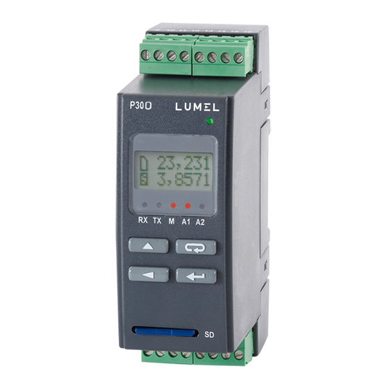
- Page 3 Rys.1. Gabaryty i sposób mocowania przetwornika. 2.2. Schematy podłączeń zewnętrznych Schematy podłączeń przedstawiono na rys. 2-4, na stronie 38. 3. OBSŁUGA 3.1 Opis p³yty czo³owej przetwornika P30o Rys.5. Opis płyty czołowej przetwornika.
- Page 4 Uwaga: Kartę pamięci (opcja) należy umieszczać w przetworniku stykami do dołu. Opis wskaźnika diodowego: RX – dioda zielona – wskaźnik odbioru danych na łączu RS-485 TX – dioda żółta – wskaźnik nadania danych na łączu RS-485 M – dioda czerwona – wskaźnik zapełnienia wewnętrznej pamięci archiwum oraz wskaźnik zapisu na karcie SD/SDHC - gdy wypełnienie pamięci wewnętrznej przekroczy 95% dioda świeci na stałe, jeżeli przetwornik pracuje z zainstalowaną...
-
Page 5: Funkcje Przycisków
(pkt.5.5.4 - patrz pełna wersja in- strukcji obsługi, dostępna na www.lumel.com.pl). Na wskaźniku dio- dowym sygnalizowany jest stan transmisji na łączu RS-485, stan zajętości wewnętrznej pamięci oraz stany alarmów. Dla przetworni- ków wyposażonych w interfejs Ethernet startują... - Page 6 (patrz pkt. 5.5.1.2 - patrz pełna wersja instrukcji obsługi, dostępna na www.lumel.com.pl) • włączenie zasilania przetwornika z przytrzymanym przyciskiem – wejście w tryb aktualizacji oprogramowania przez interfejs RS-485, parametry łącza: prędkość 115200 kb/s, tryb 8N2. - przycisk rezygnacji •...
- Page 7 - przytrzymanie około 1 sekundy • zatrzymanie zliczania włączonego licznika wejścia głównego - - jeżeli funkcja sterowania licznikiem wejścia głównego z klawiatury jest włączona; po zatrzymaniu licznika na górnym wierszu wyświetla- cza zostanie wyświetlony komunikat o zatrzymaniu licznika Rys.9. Komunikat o zatrzymaniu licznika głównego •...
- Page 8 3.3.3. Matryca programowania Rys.11. Algorytm obsługi przetwornika P30O...
- Page 9 3.4. Programowanie parametrów przetwornika Naciśnięcie przycisku i przytrzymanie go przez około 3 sekundy powoduje wejście do matrycy programowania. Jeżeli wejście jest zabezpieczone hasłem wówczas wyświetlony zo- stanie komunikat o konieczności wpisania hasła. Jeżeli wpisane zosta- nie niepoprawne hasło wyświetlony zostanie komunikat Zly kod.
- Page 10 Skala WartSkal Fun.Zewn Czas pom Typ wej Wybór Czas Stała metody Zezwolenie Ustawien Typ mierzo- uśredniania przeskalowu- przeskaowa- na funkcje Wej.Glow nej wielkośc wartości jąca wielkość nia wielkości zewnętrzne mierzonej wejściową wejściowej MaksCzas AutoKas. Korelacj Parametry Wybór typu wejścia Maksymal- Próg auto- zależności...
- Page 11 FiltrNis Funk.Mat KasujEks Kasuj Li FiltrWys Maksymal- Operacja Minimalny ny czas funkcji ma- Kasowanie Kasowanie czas trwania trwania tematycznej wartości wartości niskiego wysokiego na wartości min. i maks. licznika poziomu poziomu mierzonej impulsu impulsu Ostatni punkt ch-ki ind. Funk.Mat FiltrNis FiltrWys KasujEks...
- Page 12 Jednost Przekr.D Przekr.G Podswiet Ustawien PktDzies Wyswietl Mini- Wyświetla- malny punkt Dolny próg Górny próg Czas Parametry dziesiętny zakresu zakresu podświetlenia wyświe- jednostka wartości wyświetlania wyświetlania wyświetlacza -tlania wyświetlanej OpoZalA1 Typ A1 ProgDoA1 ProgGoA1 Ustawien Wielk.A1 Alarm 1 Typ wielk. Opóźnienie Typ alarmu Dolny próg...
- Page 13 Rej.Wysw Intens. Pk Dz.2 Jednost2 Numer Mini- rejestru Intensywność malny punkt Jednostka wysw. na podświetlenia dziesiętny drugiej dolnym wyświetlacza drugiej wartości wierszu wartości wyswiet- wyświetlanej lacza OpoPonA1 PodSygA1 OpoWylA1 Opóźnienie Podtrzyma- Opóźnienie ponownego -nie wyłączenia załączenia sygnalizacji alarmu 1 alarmu 1 alarmu 1 OpoWylA2...
- Page 14 Maska 32 AdrIP 32 AdrIP 10 Maska 10 DHCP B3,B2 bajt B1,B0 bajt B3,B2 B1,B0 bajt Włączenie/ adresu IP adresu IP bajt maski maski pod- wyłączenie (IPv4) (IPv4) podsieci sieci klienta DHCP Ustawien uzyskane z DHCP lub wprowadzone ręcznie gdy DHCP wyłączone, Ethernet il.p.TCP Adr mTCP...
- Page 15 brama 32 MAC 54 MAC 32 Brama 10 MAC 10 B1,B0 bajt B1,B0 bajt B3,B2 bajt B5,B4 bajt B3,B2 bajt adresu adresu adresu bramy adresu MAC adresu MAC bramy MAC prze- domyślnej przetwornika przetwornika domyślnej twornika format: B3.B2.B1.B0 format : B5:B4:B3:B2:B1:B0 p.komFTP PortHTTP...
-
Page 16: Dane Techniczne
3.4.2. Zmiana wartości zmiennoprzecinkowych Zmiana wykonywana jest w 2 etapach (przejście do następ- nego etapu następuje po wciśnięciu przycisku • ustawienie pozycji kropki (00000., 0000.0, 000.00, 00.000, 0.0000); przycisk przesuwa kropkę w lewo, natomiast przy- cisk przesuwa kropkę w prawo. Wciśnięcie przycisku w trakcie zmiany wartości parametru spowoduje zrezyg- nowanie z zapisu. - Page 17 Wejście pomocnicze Tablica 2 Zakres Zakres Typ wejścia nr 2 Klasa znamionowy maksymalny -99999...99999 -99999..99999 ±1 impuls Licznik impulsow 0,05...10000 Hz 0,05...12000 Hz 0,01 Czestotliwosc f < 10 kHz 0...60000 [Rot/min] 0...72000 [Rot/min] 0,01 Predkosc obrotowa 0,0001...20 [s] 0,0001...21 [s] 0,05 Okres t <...
- Page 18 Zapewniony stopień ochrony przez obudowę od strony obudowy (wykonanie bez obsługi kart SD/SDHC) IP40 od strony obudowy (wykonanie z obsługą kart SD/SDHC) IP30 od strony zacisków IP20 Pole odczytowe: tekstowy wyświetlacz LCD 2x8 znaków z podświetleniem LED Czas wstępnego wygrzewania przetwornika: 15 min Rejestracja Rejestracja do wewnętrznej pamięci 4MB (maks.
- Page 19 5. KODY WYKONAŃ Tablica 3 P30O - Wyjście analogowe: prądowe (zakres 0/4...20 mA) napięciowe (0...10 V) Dodatkowe wyposażenie: brak zewnętrzne gniazdo SD/SDHC interfejs Ethernet z wew. pamięcią systemu plików Wyjście dodatkowe: przekaźnik zwierny, 5 A 30 V d.c., 250 V a.c. zasilające 24 V d.c.
-
Page 20: Basic Requirements, Operational Safety
1. BASIC REQUIREMENTS, OPERATIONAL SAFETY The transducer meets the requirements of EN 61010-1 standard in terms of operational safety. Safety precautions: • The assembly and installation of electrical connections must be carried out by a person authorized to install electrical equipment. •... -
Page 21: External Connections Diagrams
Lock Fig.1. Overall dimensions and method of mounting the transducer. 2.2. External connections diagrams Connection diagrams are presented on fi g.2-4, on page 38. 3. OPERATION 3.1 P30o transducer front panel description Fig.3. Front panel description... -
Page 22: Messages After Switching On The Power
Note: The memory card (option) should be inserted to the transducer slot with contacts facing down. LED indicator description: RX – green diode – Date reception on RS-485 indicator TX – yellow diode – Date transmission on RS-485 indicator M – red diode – full internal memory indicator or writing fi le to SD/SDHC memory indicator, when the internal memory usage exceeds 95%, the diode is constantly on, if the transducer operates with an installed memory card, then the LED fl... -
Page 23: Individual Key Functions
(section 5.5.4 - see full version of user’s manual, ava- ilable at www.lumel.com.pl). The LED indicator signals the transmis- sion status on the RS-485 interface, status of the internal memory use and alarm states. -
Page 24: Functions Of Key Combinations
Value by the absolute setter step, (see section 5.5.1.2-- see full version of user’s manual, available at www.lumel.com.pl), • switching the transducer power supply on while holding this key enters the software update mode through the RS-485 interface, connection parameters: rate 15200 kb/s, mode 8N2. - Page 25 - hold for about 1 second • stops counting on main input counter if the counting has been swit- ched on before – works only if the keypad control counter function is switched on; after the counter is stopped the message about stop- ping the counter will be displayed on the upper display line Fig.
-
Page 26: Programming Matrix
3.3.3. Programming matrix Fig. 9. P30o operation algorithm... -
Page 27: Programming Transducer Parameters
3.4. Programming transducer parameters Press and hold for about 3 seconds key to enter the programming matrix. If access is password protected, transducer will ask for password. If the entered password is incorrect, Err.Code message will displayed. Correct password enables cess to the programming matrix. - Page 28 Input AvgTime Scale ScaleVal Ext.Func Measured Selection External Constant Measured value of the input functions scaling input Settings value type averaging value scaling mode value Main Inp time mode Correlat AutoRst. MaxTime Main input Selection Maximum parameters of the time of pe- Automatic dependence...
- Page 29 Math Fun Filtr.Hi Filtr.Lo EraseExt RstCount Mathematical Erasing function Minimum Minimum min. and Reset operation on low level high level max. counter the measured impulse impulse values . value value duration duration The last point of the indivi- dual char. Math Fun EraseExt RstCount...
- Page 30 Over Lo Unit Over Hi DecimalP Bcklight Settings Display Minimum decimal Displayed Lower Upper Display back- Display point of the unit display range display range light time parameters displayed threshold threshold value Type A1 OverLoA1 OverHiA1 DlyOnA1 Settings Param.A1 Alarm 1 Alarm Input value...
- Page 31 Dec.P 2 Unit2 Disp.Reg Bckl.Int Number Minimum of register decimal Unit LCD display displayed point of of second backlight at the lower the second displayed intensity line of the displayed value display value DlyOffA1 OnLockA1 SgKeepA1 Alarm 1 Alarm 1 Alarm 1 deactivation reactivation...
- Page 32 mask 32 addrIP32 addrIP10 mask 10 DHCP B3,B2 byte of IP B1,B0 byte B3,B2 byte B1,B0 byte address of IP address of subnet of subnet DHCP client (IPv4) (IPv4) mask mask on/off Settings received from DHCP or entered manually when DHCP is off, Ethernet no.c.TCP Port FTP...
- Page 33 gate 32 MAC 32 gate 10 MAC 54 MAC 10 B5,B4 B3,B2 B1,B0 B3,B2 byte B1,B0 byte byte of the byte of the byte of the of default of default transducer’s transducer’s transducer’s gateway gateway address address address address address format: B3.B2.B1.B0...
-
Page 34: Technical Data
3.4.2. Changing fl oating-point values The change is carried out in two stages. (the transition to the next stage follows after pressing the key. • setting the dot position (00000., 0000.0, 000.00, 00.000, 0.0000); key moves the dot to the left, and key mo- ves the dot to the right. - Page 35 Auxiliary input: Table 2 Accuracy Input type Nominal range Maximum range class -99999...99999 -99999..99999 ±1 impuls Pulse Counter 0,05...10000 Hz 0,05...12000 Hz 0.01 Frequency f < 10 kHz 0...60000 [Rot/min] 0...72000 [Rot/min] 0.01 Rotary speed 0.0001...20 [s] 0,0001...21 [s] 0.05 Period t <...
- Page 36 Insured protection grade by the housing housing-side (variant incompatible with SD/SDHC cards) IP40 housing-side (variant compatible with SD/SDHC cards) IP30 terminals-side IP20 Display: alphanumeric LCD display 2x8 characters with LED backlight Warm-up time: 15 min Recording Recording into the internal 4 MB memory (max. 534,336 records) – recording with time stamp, for variants compatible with SD/SDHC - possiblity to automatically writing internal archive into SD/SDHC cards.
-
Page 37: Ordering Code
9. ORDERING CODE Table 3 P30O - Analog output: current (0/4...20 mA) voltage (0...10 V) Additional equippment: without any with external SD/SDHC slot with Ethernet interface and internal fi le system memory Additional output: Relay (normally opened) 5 A 30 V d.c., 250 V a.c. supply 24 V d.c. - Page 38 SCHEMATY PODŁĄCZEŃ ELECTRICAL CONNECTIONS Rys.2. Schemat podłączeń elektrycznych przetwornika P30O. Fig. 2. External connections diagram of the P30o transducer...
- Page 39 1. Szczegółowe informacje o typach i funkcjonalności wejść pomiarowych zostały opisane w pkt. 5.5.1. - patrz pełna instrukcja obsługi, dostępna na www.lumel.com.pl. Tablica 4 Nr zacisków Użyte wejścia fi zyczne wymaganych do podłączenia...
- Page 40 1. Detailed information on types and functions of measurement inputs have been discussed in section 5.5.1. - see full version of user’s manual, available at www.lumel.com.pl. Table 4 No. of terminals...
- Page 41 Przykłady podłączeń / Connection examples Przykład podłączenia przetwornika P30O i czujnika indukcyjnego z wyjściem typu NPN i PNP przedstawiono na rys. 3. Sposób podłączenia przetwornika z wyjściem typu kontaktron/przekaźnik przedstawiono na rys. 5. W przykładach pokazano podłączenie wejścia głównego oraz wejścia pomocniczego do pomiaru tego samego sygnału. Zakres napięć...
- Page 42 SUPPLY OUTPUT WE1/ INP1 WE2/ INP2 KONTAKTRON PRZEKAŻNIK CONTACTRON RELAY Rys.4. Schemat podłączenia czujnika z wyjściem typu kontaktron / przekaźnik Fig. 4. Connection diagram for the sensor with a contactron/ relay type output...
- Page 44 LUMEL S.A. ul. Sulechowska 1, 65-022 Zielona Góra, Poland tel.: +48 68 45 75 100, fax +48 68 45 75 508 www.lumel.com.pl Informacja techniczna: tel.: (68) 45 75 306, 45 75 180, 45 75 260 e-mail: sprzedaz@lumel.com.pl Realizacja zamówień: tel.: (68) 45 75 207, 45 75 209, 45 75 218, 45 75 341 fax.: (68) 32 55 650...
Need help?
Do you have a question about the P300 and is the answer not in the manual?
Questions and answers