Table of Contents
Advertisement
Quick Links
Advertisement
Table of Contents

Related Manuals for Hantek HT824


Summary of Contents for Hantek HT824
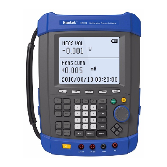
- Page 1 HT824 Multifunction Process Calibrator Calibration Manual V 1.1...
-
Page 2: Table Of Contents
Index Introduction......................... 1 Safety Information......................1 Required Equipment....................2 Lower Display Voltage (V) Measurement Calibration.......... 3 Lower Display Voltage (mV) Measurement Calibration........4 Lower Display Current (mA) Measurement Calibration........5 Lower Display Thermocouple Measurement Calibration........6 Lower Display Resistance Measurement Calibration.......... 7 Lower Display Voltage (V) Source Calibration............ 11 Lower Display Voltage (mV) Source Calibration..........12 Lower Display Current (mA) Source Calibration..........13 Lower Display Thermocouple (TC) Source Calibration........ -
Page 3: Introduction
HT824 Calibration Manual Introduction Warning The information provided in this manual is for the use of qualified personnel only. Do not perform the calibration procedures described in this manual unless you are qualified to do so. This Calibration Manual provides the following information for the Hantek824 Multifunction Process Calibrator (also referred to as "the Calibrator"... -
Page 4: Required Equipment
HT824 Calibration Manual Required Equipment Equipment required to perform the procedures in this manual are identified in Table 1-3. Table 1. Required Equipment for Lower Measurement Calibration Equipment Minimum Specifications DC voltage Source Range: 0 V to 30.0000 V Resolution: 0.0005 V Accuracy: 0.02 % rd + 2... -
Page 5: Lower Display Voltage (V) Measurement Calibration
HT824 Calibration Manual Lower Display Voltage (V) Measurement Calibration 1. Turn on the Calibrator, press to get to the measure mode, then press until MEAS and VOL appear on the lower display. 2. Set up the standard voltage output source to output 0.000V; Connect positive electrode to terminal V/Ω... -
Page 6: Lower Display Voltage (Mv) Measurement Calibration
HT824 Calibration Manual Lower Display Voltage (mV) Measurement Calibration 1. Turn on the Calibrator, press to get to the measure mode, then press until MEAS and MVOL appear on the lower display. 2. Set up the standard voltage output source to output 0.000mV; Connect positive electrode to terminal V/Ω... -
Page 7: Lower Display Current (Ma) Measurement Calibration
HT824 Calibration Manual Lower Display Current (mA) Measurement Calibration 1. Turn on the Calibrator, press to get to the measure mode, then press until MEAS and CURR appear on the lower display. 2. When the Calibrator display readings stable, if the reading is not 0.000mA,... -
Page 8: Lower Display Thermocouple Measurement Calibration
HT824 Calibration Manual Lower Display Thermocouple Measurement Calibration 1. Turn on the Calibrator, press to get to the measure mode, then press until MEAS and TC appear on the lower display. 2. Set up the standard voltage output source to output -10.000mV; Connect a Type-J thermocouple lead between the TC jack on the top of the Calibrator and the TC jack on the voltage output source. -
Page 9: Lower Display Resistance Measurement Calibration
HT824 Calibration Manual Lower Display Resistance Measurement Calibration 1. Turn on the Calibrator, press to get to the measure mode, then press until MEAS and RTD appear on the lower display. 2. Use to get to the 2W mode. 3. Make the connections shown in Figure 5. When the Calibrator display readings stable, if the reading is not 0Ω, please press... - Page 10 HT824 Calibration Manual Set up the standard resistance box to output 4000.0Ω resistance. When the Calibrator display readings stable, if the reading is not 4000.0Ω, press simultaneously until the Calibrator display 4000.0Ω, then resistance readings are within the 3999.7Ω to 4000.3Ω.
- Page 11 HT824 Calibration Manual Set up the standard resistance box to output 4000.0Ω resistance. When HT824 display readings stable, if the reading is not 4000.0Ω, press simultaneously until the Calibrator display 4000.0Ω, then resistance readings are within the 3999.7Ω to 4000.3Ω.
- Page 12 HT824 Calibration Manual Set up the standard resistance box to output 4000.0Ω resistance. When the Calibrator display readings stable, if the reading is not 4000.0Ω, press simultaneously until the Calibrator display 4000.0Ω, then resistance readings are within the 3999.7Ω to 4000.3Ω.
-
Page 13: Lower Display Voltage (V) Source Calibration
HT824 Calibration Manual Lower Display Voltage (V) Source Calibration 1. Turn on the Calibrator, press to get to the source mode, then press until OUT and VOL appear on the lower display. 2. Connect the terminal V/Ω and COM of the Calibrator to the voltage measurement terminals of the calibritor. -
Page 14: Lower Display Voltage (Mv) Source Calibration
HT824 Calibration Manual Lower Display Voltage (mV) Source Calibration 1. Turn on the Calibrator, press to get to the source mode, then press until OUT and MVOL appear on the lower display. 2. Connect the terminal V/Ω and COM of the Calibrator to the voltage measurement terminals of the calibritor. -
Page 15: Lower Display Current (Ma) Source Calibration
HT824 Calibration Manual Lower Display Current (mA) Source Calibration 1. Turn on the Calibrator, press to get to the source mode, then press until OUT and CURR SOUR appear on the lower display. 2. Connect the terminal mA+/3W and mA-/4W of the Calibrator to the current measurement terminals of the calibritor. -
Page 16: Lower Display Thermocouple (Tc) Source Calibration
HT824 Calibration Manual Lower Display Thermocouple (TC) Source Calibration 1. Turn on the Calibrator, press to get to the source mode, then press until OUT and TC appear on the lower display. 2. Connect the TC jack on the top of the Calibrator to the voltage measurement terminals of the calibritor. -
Page 17: Lower Display Resistance (Ω) Source Calibration
HT824 Calibration Manual Lower Display Resistance (Ω) Source Calibration 1. Turn on the Calibrator, press to get to the source mode, then press until OUT and RTD appear on the lower display. 2. Connect the terminal V/Ω and COM of the Calibrator to the resistance measurement terminals of the calibritor. - Page 18 HT824 Calibration Manual 6. Press simultaneously until the Calibrator display SCAL (to get to full scale calibration). If the display resistance (4000Ω) differ with the measured resistance on the calibrator, press arrow keys set the Calibrator output until the two display same.
-
Page 19: Upper Display Voltage (V) Measurement Calibration
HT824 Calibration Manual Upper Display Voltage (V) Measurement Calibration 3. Turn on the Calibrator, press to get to the measure mode, then until MEAS and VOL appear on the upper display. press 2. Set up the standard voltag output source to output 0.000V voltage; Connect positive electrode to terminal V/Loop and connect negative electrode to terminal COM on the top of the Calibrator. - Page 20 HT824 Calibration Manual 5. When the Calibrator display readings stable, if the reading is not 20.000V, please press simultaneously until the Calibrator display 20.000V, then readings are within the limit 19.997 V to 20.003V. www.hantek.com...
-
Page 21: Upper Display Current (Ma) Measurement Calibration
HT824 Calibration Manual Upper Display Current (mA) Measurement Calibration 1. Turn on the Calibrator, press to get to the measure mode, then press until MEAS and CURR appear on the upper display. 2. Set up the standard current output source to output 0.000mA current. Connect positive electrode to terminal mA and connect negative electrode to terminal COM on the top of the Calibrator. - Page 22 HT824 Calibration Manual 5. When the Calibrator display readings stable, if the reading is not 22.000mA, please press simultaneously until the Calibrator display 20.000mA, then readings are within the limit 21.997mA to 22.003mA. www.hantek.com...
-
Page 23: Upper Display Current (Loop) Measurement Calibration
HT824 Calibration Manual Upper Display Current (LOOP) Measurement Calibration 1. Turn on the Calibrator, press to get to the measure mode, then press until MEAS and LOOP appear on the upper display. 2. Set up the analog current output source to output 22.000mA. Connect positive electrode to terminal V/Loop and connect negative electrode to terminal COM on the top of the Calibrator.
Need help?
Do you have a question about the HT824 and is the answer not in the manual?
Questions and answers