
Related Manuals for visual engineering MFR-DB


Summary of Contents for visual engineering MFR-DB
- Page 1 MFR-DB December 2021 MFR-DB User Manual User Guide for the MFR-DB Dual Optical & Thermal PTZ Camera visualengineering.co.uk Page 1...
-
Page 2: Table Of Contents
MFR-DB December 2021 Table of Contents Document History � � � � � � � � � � � � � � � � � � � � � � � � � � � � � � � � � � � � � � � � � � � � � � � � � � � � � � � � � � � � � � � � � � � � � � 3 Warranty and Support �... -
Page 3: Document History
09/12/2021 Environmental Update Warranty and Support All Visual Engineering products are supplied as standard with a 12 month ‘Return to Base’ warranty� Please note: Any unauthorised product disassembly, modification or the removal of tamper proof labels will void the warranty. -
Page 4: Introduction
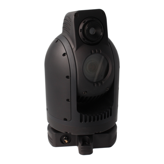
December 2021 Introduction The MFR-DB is a dual band PTZ camera incorporating both an optical and a thermal camera� Housed in a very rugged environmentally sealed casing it is ideal for use in harsh environments� It incorporates a Sony HD camera with a 30x optical zoom lens and a 63�7° wide angle of view�... -
Page 5: Connections
December 2021 Connections The MFR-DB kit includes a power comms break out cable, part number 110-3562� The cable assembly connects to the Fischer MiniMax connector on the base of the camera� All signals are then split out to their relevant connectors� The connections are described below�... -
Page 6: Configuring The Camera
December 2021 Configuring the Camera The MFR-DB can be configured for a specific user profile, to include; communication settings, motor control, and camera options. Once configured the camera will retain the settings. The camera is configured using a menu structure on its control interface which is only accessible at power on�... -
Page 7: Motor Options
MFR-DB December 2021 Motor Options Motor Options Sub Menu Description Options Whether the camera automatically corrects Auto Position its actual position if external forces Disabled, Enabled Correction act upon it Stall Detection Detects a stall in the motor drive Disabled, Enabled... -
Page 8: Boot Confirmation
MFR-DB December 2021 Boot Confirmation This gives a clear visual confirmation at power on whether or not the MFR-DB Camera has initialised successfully the following hardware is tested during boot sequence: • Optical Camera Module Comms • Thermal Camera Module Comms •... -
Page 9: Software Control
December 2021 Software Control The MFR-DB camera’s serial communication supports PelcoD, PelcoP & Sony VISCA protocols� The user may choose to use a software controller of their choice or use the VE Camera Controller� This software application can be downloaded from the Visual Engineering website: www�visualengineering�co�uk/supportdownload/9... - Page 10 MFR-DB December 2021 It is necessary to connect the camera to a USB port on the PC� The operating system of the computer will allocate this a COM port number� Once this connection has been made the user can go ahead and connect the application to the COM port� In the example below the port COM3 has been selected�...
-
Page 11: Camera Commands
Comm Port Options in the boot menu� Response Acknowledge [y]0 0x41 0xFF Response Complete [y]0 0x51 0x24 0x92 [ab] 0xFF = The Unit Address+8� [ab] = The Unit Type, as defined: • MFR-HD = 0x11 • MFR-DB = 0x12 visualengineering.co.uk Page 11... -
Page 12: Flir Pass Through
MFR-DB December 2021 Flir Pass Through Through the camera’s serial comms path the thermal camera module can be controlled using standard FLIR protocol, which is wrapped using the following custom VISCA command/response� The payload of the command/response is the standard FLIR command�... -
Page 13: Specifications
MFR-DB December 2021 Specifications Specifications Optical Sensor 1/2�8” Type CMOS Radiometric Technology As Standard Optical Sensitivity < 0�05 Lux, ICR On Thermal Spot Metering Enabled Optical Resolution 1920 x 1080 Pixel Serial Protocol RS232/485 Visca, PelcoD Optical SNR > 50dB Pan Range 360°... -
Page 14: Dimensions
MFR-DB December 2021 Dimensions Overall Dimensions Base Plate Hole Centres Visual Engineering Technologies LTD Product specifications subject to change without notice Kemps Farm Stanway Colchester Essex Tel: +44 (0)1206 211842 CO3 8NB Web: www�visualengineering�co�uk Email: sales@visualengineering�co�uk visualengineering.co.uk Page 14...
Need help?
Do you have a question about the MFR-DB and is the answer not in the manual?
Questions and answers