
Related Manuals for visual engineering MFR-TI


Summary of Contents for visual engineering MFR-TI
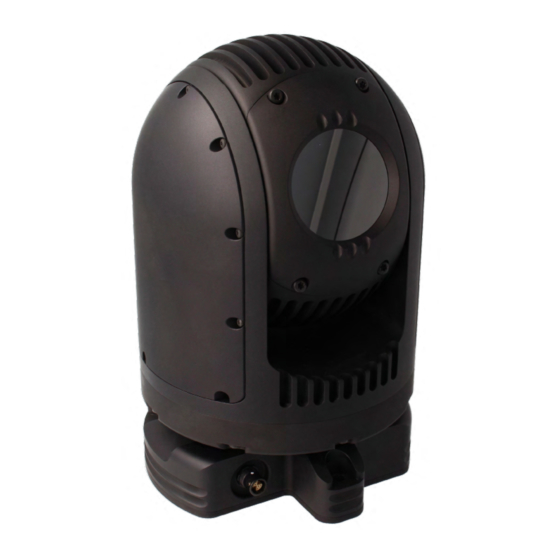
- Page 1 MFR-TI April 2022 MFR-TI User Manual User Guide for the MFR-TI Thermal PTZ Camera visualengineering.co.uk Page 1...
-
Page 2: Table Of Contents
MFR-TI April 2022 Table of Contents Document History � � � � � � � � � � � � � � � � � � � � � � � � � � � � � � � � � � � � � � � � � � � � � � � � � � � � � � � � � � � � � � � � � � � � � � 3 Warranty and Support �... -
Page 3: Document History
11/04/2022 Initial Release Warranty and Support All Visual Engineering products are supplied as standard with a 12 month ‘Return to Base’ warranty� Please note: Any unauthorised product disassembly, modification or the removal of tamper proof labels will void the warranty. -
Page 4: Introduction
MFR-TI April 2022 Introduction The MFR-TI is a thermal PTZ camera which is housed in a very rugged environmentally sealed casing making it ideal for use in harsh environments� The Flir thermal camera incorporates radiometric technology which delivers high precision temperature monitoring�... -
Page 5: Connections
April 2022 Connections The MFR-TI kit includes a power comms break out cable, part number 110-3562� The cable assembly connects to the Fischer MiniMax connector on the base of the camera� All signals are then split out to their relevant connectors� The connections are described below�... -
Page 6: Configuring The Camera
April 2022 Configuring the Camera The MFR-TI can be configured for a specific user profile, to include; communication settings, motor control, and camera options. Once configured the camera will retain the settings. The camera is configured using a menu structure on its control interface which is only accessible at power on�... -
Page 7: Motor Options
MFR-TI April 2022 Motor Options Motor Options Sub Menu Description Options Whether the camera automatically corrects Auto Position its actual position if external forces Disabled, Enabled Correction act upon it Stall Detection Detects a stall in the motor drive Disabled, Enabled... -
Page 8: Software Control
April 2022 Software Control The MFR-TI camera’s serial communication supports the Sony VISCA protocol� The user may choose to use a software controller of their choice or use the VE Camera Controller� This software application can be downloaded from the Visual Engineering website: www�visualengineering�co�uk/supportdownload/9... - Page 9 MFR-TI April 2022 It is necessary to connect the camera to a USB port on the PC� The operating system of the computer will allocate this a COM port number� Once this connection has been made the user can go ahead and connect the application to the COM port� In the example below the port COM3 has been selected�...
-
Page 10: Camera Communications
Additional commands adopting the VISCA protocol format have been developed by Visual Engineering for use with the MFR-TI camera� These commands also allow control of a limited set of parameters in the Flir thermal camera when using standard VISCA controllers�... -
Page 11: Flir-Pass-Through
Unit Type 8x 01 04 24 92 00 01 FF Y0 51 24 92 <aa> FF TYPE 0x12 = MFR-DB 0x13 = MFR-TI <pppp> = Pan Position <tttt> = Tilt Position The value returned is a 16-bit PAN TILT Absolute... - Page 12 By way of example the following illustrates how the Flir-Pass-Through mode format and standard Flir commands can be combined into a single VISCA style packet for the MFR-TI� The examples address a Unit ID of 1, all values are hexadecimal�...
-
Page 13: Specifications
MFR-TI April 2022 Specifications Specifications Resolution 640 x 512 Pixel User Presets Lens Pan Range 360° Field of View 69° H, 56° V Tilt Range 240° NEdT < 30mK Connector Fischer MiniMax Radiometric Technology As Standard Environmental IP67 Thermal Spot Metering... -
Page 14: Dimensions
MFR-TI April 2022 Dimensions Overall Dimensions ø 115 Base Plate Hole Centres Visual Engineering Technologies LTD Product specifications subject to change without notice Kemps Farm Stanway Colchester Essex Tel: +44 (0)1206 211842 CO3 8NB Web: www�visualengineering�co�uk Email: sales@visualengineering�co�uk visualengineering.co.uk Page 14...
Need help?
Do you have a question about the MFR-TI and is the answer not in the manual?
Questions and answers