
Related Manuals for Henny Penny WENDY'S EVOLUTION ELITE EEE-151


Summary of Contents for Henny Penny WENDY'S EVOLUTION ELITE EEE-151
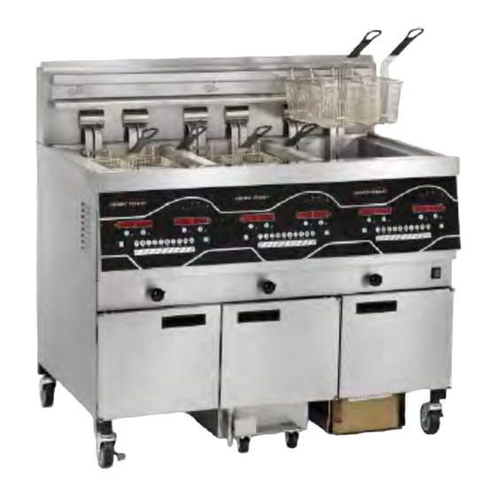
- Page 1 OPERATOR’S M A N U A L WENDY’S EVOLUTION ELITE™ (Electric) REDUCED OIL CAPACITY OPEN FRYER MODEL EEE-151 EEE-152 EEE-153 EEE-154 R E G I S T E R W A R R A N T Y O N L I N E AT W W W. H E N N Y P E N N Y. C O M...
- Page 2 These are the original version controlled Henny Penny instructions for Evolution Elite Electric (EEE) 1, 2, 3 and 4 vat model 151, 152, 153, 154 (EEE 151, 152, 153, 154). This manual is available on the Henny Penny Public website (www.hennypenny.com). Read these instructions completely prior to installation and operation of this appliance to ensure compliance to all required installation, operation and safety standards.
-
Page 3: Table Of Contents
TABLE OF CONTENTS Section Page Section 1. INTRODUCTION ..................... 1 Introduction ....................1 Features......................1 Proper Care ....................1 Assistance ...................... 2 Safety ......................2 Section 2. INSTALLATION ....................... 4 Introduction ....................4 Unpacking...................... 4 Selecting the Fryer Location ................. 5 Leveling the Fryer .................. - Page 4 TABLE OF CONTENTS (Continued) Section Page Section 4. INFORMATION MODE ................48 Information Mode Details ..............48 Section 5. PRODUCT PROGRAM MODE ..............53 Modifying Product Settings ..............53 Section 6. LEVEL 2 PROGRAMMING ................56 Special Program Mode ................ 56 Do Not Disturb ..................
-
Page 5: Introduction
SECTION 1. INTRODUCTION 1-1. INTRODUCTION The Henny Penny open fryer is a basic unit of food processing equipment designed to cook foods better and easier. The micro computer-based design helps make this possible. This unit is used only in institutional and commercial food service operations, and operated by qualified personnel. -
Page 6: Assistance
1-4. ASSISTANCE Should you require outside assistance, call your local independent distributor in your area, or call Henny Penny Corp. at 1-800-417-8405 or 1-937-456-8405. 1-5. SAFETY The Henny Penny open fryer has many safety features incorporated. However, the only way to ensure a safe operation is to fully under stand the proper installation, operation, and maintenance procedures. - Page 7 1-5. SAFETY (Continued) Equipotential Ground Symbol Waste Electrical and Electronic Equipment (WEEE) Symbol Shock Hazard Symbols Hot Surface Symbols Aug. 2011...
-
Page 9: Installation
Cut and remove the metal bands from the carton. Remove carton lid and lift the main carton off the fryer. THIS DRAWING IS THE CONFIDENTIAL AND PROPRIETARY PROPERTY OF HENNY PENNY CORP. Remove corner packing supports (4). Cut the stretch film from around the carrier/rack box and remove it from the top of the fryer lid. -
Page 10: Selecting The Fryer Location
2-3. SELECTING THE FRYER The proper location of the fryer is very important for operation, speed, and convenience. The location of the open fryer should LOCATION allow clearances for servicing and proper operation. Choose a location which will provide easy loading and unloading with- out interfering with the final assembly of food orders. Opera- tors have found that frying from raw to finish, and holding the product in warmers provides fast continuous service. -
Page 11: Ventilation Of Fryer
2-5. VENTILATION OF FRYER The fryer should be located with provision for venting into an adequate exhaust hood or ventilation system. This is es- sential to permit efficient removal of the steam exhaust and frying odors. Special precaution must be taken in designing an exhaust canopy to avoid interference with the operation of the fryer. - Page 12 2-6. ELECTRICAL An all pole, separate disconnect switch, with proper capacity REQUIREMENTS fuses or breakers must be installed at a convenient location (Continued) between the fryer and the power source, and must be installed according to national and local codes. It should be an insulated copper conductor rated for 600 volts and 90°...
-
Page 13: Dimensions
2-7 Dimensions Figure 2-7 EEE-15X Dimensions • Front to rear dimension is 36- 7/8 “ (93.66 cm). I I N N F F O O : • For doorways 36 in. (91.44 cm) or less, the protective bumper bar on the rear of the fryer must be temporarily removed. -
Page 14: Operation
SECTION 3. OPERATION 3-1. OPERATING COMPONENTS Refer to explanations on the next pages. Figure 3-1 Figure 3-3 Figure 3-2 Aug. 2014... - Page 15 3-1. OPERATING COMPONENTS Refer to Figures 3-1, 3-2 & 3-3 in conjunction with the descrip- (Continued) tion of the functions below. Fig. Item Description Function This LED lights when the control calls for heat for the left vat(s), and the elements come on and heats the oil During normal operation, press this button to start and stop cook cycles for the left basket;...
- Page 16 3-1. OPERATING COMPONENTS (Continued) Fig. Item Description Function 10 & 11 Each product button LED lights when that particular product has been selected, or when it is compatible with cook temperature Press to select the desired product; press to place the letters under the button, during naming a product in Program Mode can be used to start an Idle Mode if enabled in Special Program Mode...
- Page 17 Figure 3-4 Fig. Item Description Function Filter Drain Pan Assy. Oil is drained into this pan and then is pumped through filters to help prolong the use of the oil Basket Rest The baskets hang on this when not in use, or to drain the product after a cook cycle Vat Covers Covers the vat when not in use Drain Valve Knob...
-
Page 18: Set-Up Mode
3-2. SET-UP MODE Upon initial start-up, the controls will ask to confirm the settings for the fryer. When the main power switch is turned on, “OFF” shows in both displays. Press on either side and *SETUP* *ENTER CODE* shows in the displays. Press 1, 2, 3, and “LANGUAGE” shows on the left display, “ENGLISH” on the right display. buttons to change the operation display to, Greek “EΛΛHNIKA”, Russian “РУССКИИ”, Swedish “SVENSKA”, German “DEUTSCHE”, Portuguese “POR-... -
Page 19: Filling Or Adding Oil
3-3. FILLING OR ADDING OIL The oil level must always be above the burner tubes when the fryer is heating and at the oil level indicators on the rear of the vat. Failure to follow these instructions could result in a fire and/or damage to the fryer. Solid oil is not recommended. Solid oil could cause clogging and pump failures. -
Page 20: Morning Start-Up Procedures
3-4. MORNING START-UP PROCEDURES 1. Make sure basket support is in vat and vat is filled with oil to the proper level. 2. Move power switch to the ON position and then press to turn on heat for the desired vat. If display shows “IS POT FILLED?” make sure oil is at the proper level (see Section ü... -
Page 21: Basic Operation
3-5. BASIC OPERATION 1. Once out of the Melt Cycle, LOW TEMP flashes until the setpoint temperature is reached, and the product name shows in the display, ex: FRY. Product now can be placed in the oil. 2. Press a timer button 3. Display shows the name of the product cooking (ex: “FRY”) and the timer counting down. -
Page 22: Oil Guardian™ (Auto Top-Off)
3-7. OIL GUARDIAN™ During normal operation, the control automatically monitors (Auto Top-Off) the oil level in the vat. If the control senses the oil level too low, the unit automatically pumps oil from the BIB into the vat to keep the oil at the proper level. Manual Top-Off If the oil level is a little low, oil can be added to the vat at any time from the BIB to raise the oil level to the proper level by... - Page 23 3-9.b Model EEE-151 Oil Filling Oil Reserve 1. Control display "BIB IS LOW" and an alarm sounds. 2. Open door and pull reservoir forward and remove reservoir cover. Figure 1 Removing Reservoir Lid 3. Place reservoir cover on bracket on door. Figure 2 Reservoir in Bracket 4 4 .
-
Page 24: Filter - Manual
3-10. A FILTER - MANUAL 1. During normal operation and after a certain number of cook cycles, the Filter Beacon illuminates on the front of the fryer ® (Figure 1), and the control periodically shows “FLTR NOW?” “YES NO”. If X for NO is pressed, fryer resumes normal operation and control suggests filter later. - Page 25 3-10. A FILTER - MANUAL 6. If the oil has not pumped back to the proper level in the vat (Continued) during the SmartFilter Express™ process, press X button for NO and pump runs for another 30 seconds. 7. Display shows “IS POT FILLED?” “YES NO”. Make ü...
-
Page 26: Filter - Smart Touch
3-10. B FILTER - SMART TOUCH This section describes how to run an automatic filter procedure using the push-button feature. During normal operation and after a certain number of cook cycles, the control periodically shows “FLTR NOW?” “YES NO”. If filtering is desired, press √ button for YES and display shows “SKIM VAT”, followed by “CONFIRM” “YES NO”. Once the crumbs are skimmed off the top of the oil, press √ button for YES and display shows shows “DRAINING”... - Page 27 3-10. B FILTER - SMART TOUCH After trying to fill the vat 3 times without success, the controls then (continued) shows “CHANGE FILTER PAD?” “YES NO”. If changing the filter pad at this time, press √ and change filter pad following the proce- dures in the Changing the Filter Pad or Paper Section. Controls return to normal operation. If filter pad is to be changed at a later time, press X button and “CHANGE FILTER PAD?” reminder shows 15 minutes later. During the next AIF with a new filter pad, if the vat is not filled after 3 tries, the display shows “FILTER SERVICE REQUIRED-SEE TROUBLESHOOTING GUIDE”.
-
Page 28: Manual - Daily Filtering
3-11. A MANUAL DAILY This filtering procedure allows for a more thorough cleaning of the FILTERING vat and should be done once a day. The vat can be filtered during any non-frying times. T o avoid burns from hot oil, use approved safety equipment including, apron, face shield and gloves before starting filtering procedure. Also, to avoid overfilling the drain pan, drain only 1 vat at a time. - Page 29 3-11. A MANUAL DAILY 8. Use the lift tool and lift the hinged element from the vat to clean the bottom of the vat. Figure 4. FILTERING (Continued) Use protective cloth or gloves when lifting the element with the lift tool. The element may be hot and severe burns could result.
- Page 30 3-11. A MANUAL DAILY ü 14. Press button for YES if another rinse is needed, otherwise FILTERING press X button for NO. The display shows “POLISH?” “YES”. (Continued) ü 15. Press button for YES and the oil is “polished” by circulating it through the filtering system. The display shows “5:00 STOP POLISH”.
-
Page 31: Smart Touch - Daily Filtering
3-11. B SMART TOUCH DAILY FILTERING Put on protective gear: Be sure to use all approved safety equipment in-cluding, apron, face shield and gloves. Never begin filtering until you’re wearing all safety gear. Hot oil can cause severe burns. Moving the fryer or filter drain pan while containing hot oil is not recommended. - Page 32 3-11. B SMART TOUCH DAILY FILTERING Do not use steel wool, other abrasive cleaners or cleaners/sanitizers containing chlorine, bromine, iodine or ammonia chemicals, as these will deteriorate the stainless steel material and shorten the life of the unit. Do not use a water jet (pressure sprayer) to clean the unit, or component damage could result.
-
Page 33: Discarding Oil Using Optional Discard Shuttle-Ods-400
3-12. DISCARDING OIL USING OPTIONAL OIL DISCARD SHUTTLE-ODS-400 WITH PROLONGED USE, THE FLASHPOINT OF OIL IS REDUCED. DISCARD OIL IF IT SHOWS SIGNS OF EXCESSIVE SMOKING OR FOAMING. SERIOUS BURNS, PERSONAL INJURY, FIRE, AND/ OR PROPERTY DAMAGE COULD RESULT. 1. Open the door, lift-up on the drain pan stop and pull-out the drain pan assembly, using the handle on the drain pan. - Page 34 3-12. DISCARDING OIL USING ü 6. Press button and “IS DISPOSAL UNIT IN PLACE? OPTIONAL OIL DISCARD “YES NO”shows in display. SHUTTLE-ODS-400 (Continued) ü 7. With discard shuttle rolled into place (Figure 3), press button and display shows “OPEN DRAIN”. Pull-out on drain knob to open drain and display shows “DRAINING”.
-
Page 35: Discarding Oil Using Optional Discard Shuttle-Ods-450
3-13. DISCARDING OIL USING OPTIONAL OIL DISCARD SHUTTLE-ODS-450 WITH PROLONGED USE, THE FLASHPOINT OF OIL IS REDUCED. DISCARD OIL IF IT SHOWS SIGNS OF EXCESSIVE SMOKING OR FOAMING. SERIOUS BURNS, PERSONAL INJURY, FIRE, AND/ OR PROPERTY DAMAGE COULD RESULT. 1. Open the door, lift-up on the drain pan stop and pull-out the drain pan assembly, using the handle on the drain pan. - Page 36 3-13. DISCARDING OIL USING ü 6. Press button and “IS DISPOSAL UNIT IN PLACE? OPTIONAL OIL DISCARD “YES NO”shows in display. SHUTTLE-ODS-450 (Continued) ü 7. With discard shuttle rolled into place (Figure 3), press button and display shows “OPEN DRAIN”. Pull-out on drain knob Press down to lock to open drain and display shows “DRAINING”.
- Page 37 3-13. DISCARDING OIL USING OPTIONAL OIL DISCARD SHUTTLE-ODS-450 (Continued) 18. Plug the shuttle electrical cord into the receptacle under the disposal container control, and then press & hold switch on container controls to pump oil from shuttle to the container. Figure 9 19.
-
Page 38: Discarding Oil Using Optional Bulk Oil Dispose System
3-14. DISCARDING OIL 1. Connect the female quick disconnect, that is attached to the hose in the rear of the open fryer, to the correct male quick USING OPTIONAL BULK disconnect at the wall. Once attached, the hose can remain OIL DISPOSE SYSTEM connected unless the open fryer is moved. -
Page 39: Changing The Filter Pad
3-14. DISCARDING OIL 12. Display shows “MANUAL FILL VAT” (or “FILL VAT FROM VAT USING FROM BULK if so equipped), followed by “IS POT FILLED?”, along with “YES NO”. Fill the vat to the lower OPTIONAL BULK OIL DISPOSE SYSTEM indicator line on the rear of the vat. - Page 40 3-15. CHANGING THE FILTER PAD (Continued) 5. Remove the filter pad retaining ring and clean thoroughly with soap and water. Rinse thoroughly with hot water. Figure 5. Figure 5 6. Pull the filter pad from the pan and discard pad. Figure 6. Figure 6 7. Remove the bottom screen from pan and clean thoroughly with soap and water. Rinse thoroughly with hot water. Figure 7.
-
Page 41: Removing And Cleaning Basket Rest
3-15. CHANGING THE FILTER PAD (Continued) Be sure that drain pan, bottom screen, crumb catcher, and the retaining ring are thoroughly dry before placing filter pad into pan as water will dissolve the filter pad. 9. Reassemble in reverse order, placing the bottom screen into the filter pan first, followed by the filter pad, retaining ring and the crumb catcher. 10. -
Page 42: Clean-Out Mode - Manual
3-17. A CLEAN-OUT MODE - MANUAL The filter drain pan must be as far back under fryer as it will go, and the cover in place. Be sure filter drain pan is latched into place and hole in the cover lines up with the drain before open- ing drain. - Page 43 3-17. A CLEAN-OUT MODE - Display shows “IS DISPOSAL UNIT IN PLACE” “YES NO”. If MANUAL “NO” is selected, display shows “INSERT DIS POSAL UNIT”. (Continued) Once disposal unit is in place, press √ button for YES; display shows “OPEN DRAIN”. Open drain, display shows “DRAINING” and oil drains from vat.
- Page 44 3-17. A CLEAN-OUT MODE - Return empty filter drain pan to fryer and press √ button. Display then MANUAL shows “VAT EMTY” “YES NO”. (Continued) Once vat is empty, press √ button and display shows “SCRUB VAT COMPLETE” “YES NO”. Use brush and scour pad to clean vat, if needed. Do not use steel wool, other abrasive cleaners, or cleaners/ sanitizers contain- ing chlorine, bromine, iodine, or ammonia chemicals as these will deteriorate the stainless steel material and shorten the life of the unit.
-
Page 45: Clean-Out Mode - Smart Touch
3-17. B CLEAN-OUT MODE - SMART TOUCH The filter drain pan must be as far back under fryer as it will go, and the cover in place. Be sure filter drain pan is latched into place and hole in the cover lines up with the drain before opening drain. - Page 46 3-17. B CLEAN-OUT MODE - Display shows “VAT EMTY” “YES NO”. Press √ button when ready. SMART TOUCH (Continued) Bulk Oil Systems Only! Display shows “CHK PAN” if the filter drain pan is missing. Once pan is in place, the drain will open automatically and display will show “DRAINING” and oil drains from vat. Display then shows “√=PUMP” “X=DONE. Press √ button, display shows “DIS- POSING” and oil is pumped from drain pan. Once pan is empty, press X button twice and close drain.
- Page 47 3-17. B CLEAN-OUT MODE - Once vat is empty, press √ button and display shows “SCRUB VAT SMART TOUCH COMPLETE” “YES NO”. Use brush and scour pad to clean vat, if needed. The drain will open automatically. (Continued) Do not use steel wool, other abrasive cleaners, or cleaners/ sanitizers contain- ing chlorine, bromine, iodine, or ammonia chemicals as these will deteriorate the stainless steel material and shorten the life of the unit.
-
Page 48: Cold Soak Procedure
3-17. C COLD SOAK PROCEDURE FIRE RISK Do not exert pressure on the heating elements or fire may occur, resulting in personal injury and/or property damage. Dispose of the oil in the fryer. Fill the fryer with cleaning soution and let it sit overnight. Use the long-handled fryer brush or a blue scouring pad in an up and down motion (scour the sides of the kettle and the heating coils). -
Page 49: Check/Replace Filter Drain Pan O-Rings
3-18. CHECK/REPLACE FILTER To prevent oil leaking, and to keep filtering process operating DRAIN PAN O-RINGS properly, the filter drain pan o-rings should be inspected for nicks and tears at least every 3 months. Figure 1 1. Open the door, lift-up on the drain pan stop and pull-out the filter drain pan assembly, using the handle on the drain pan. Figures 2 & 3 This pan could be hot! Use protective cloth or glove, or Figure 1 severe burns could result. -
Page 50: Info Button Stats
3-19. INFO BUTTON STATS Actual Oil Temperature 1. Press and the actual oil temperature shows in the display, for each vat. Set-point Temperature 2. Press twice and SP shows in the display, along with the set-point (preset) temperature of each vat. Recovery Information for each Vat 3. -
Page 51: Preventive Maintenance Schedule
3-21. PREVENTIVE As in all food service equipment, the Henny Penny open fryer MAINTENANCE does require care and proper maintenance. The table below SCHEDULE provides a summary of scheduled maintenance procedures to be performed by the operator. Procedure Frequency Filtering of shortening... -
Page 53: Information Mode
Not all Information Mode functions are discussed in this section. To ensure proper operation of fryer, please consult Henny Penny Corp. before changing any of these settings. For more information on these functions, contact Technical Support at 1-800-417- 8405, or 1-937-456-8405. - Page 54 4-1. INFORMATION MODE 2. LAST LOAD (Information on recent cook cycles) DETAILS (Continued) Press and “2. LAST LOAD” show in displays. Press a timer button for the product you want to view the cook data and the LED flashes. Press button to start viewing the cook data. For example, if the left LED is flashing, “PRODUCT FRY L1”...
- Page 55 4-1. INFORMATION MODE 3. DAILY STATS (Operational info of fryer for last 7 days) DETAILS (Continued) Press and “3. DAILY STATS” show in displays. Press button to start viewing the cook data. Press the right to view data for other days of week. FUNCTION DISPLAY EX: Day this data was recorded for...
- Page 56 4-1. INFORMATION MODE 4. OIL STATS (info of current oil and avg. of last 4 batches of DETAILS (Continued) oil) Press and “4. OIL STATS” show in displays. Press button to start viewing the cook data. FUNCTION DISPLAY EX: Start date of new oil (L/R) NEW OIL MAR-23 Number of days oil in use...
- Page 57 4-1. INFORMATION MODE 5. REVIEW USAGE(accumulated info since the data was DETAILS (Continued) reset) Press and “4. REVIEW USAGE” show in displays. Press button to start viewing the cook data. FUNCTION DISPLAY EX: Day the usage data was previously reset SINCE APR-19 3:00P Number of Hours the fryer was on...
-
Page 59: Product Program Mode
SECTION 5. PRODUCT PROGRAM MODE This mode allows you to program the following: • Change Product Name • Include in Filter Count (Global) • Assign Button • Filter at X no. of loads (Mixed) • Change Times & Temp • Load Compensation •... - Page 60 5-1. MODIFYING PRODUCT To Change Times and Temperatures SETTINGS (Continued) 7. Press button until “COOK TIME” shows in the display, and then use the product buttons, or the buttons, to change the time in minutes and seconds, to a maximum of 59:59. 8.
- Page 61 5-1. MODIFYING PRODUCT Mixed Filter Tracking Filter After X Number of Loads SETTINGS (Continued) 13b. Press button until “FILTER AFTER...” flashes in the left display along, and the number of cook cycles between filters shows in the right display. Press the product buttons, or the buttons, to change this value of 0 to 99 loads. This needs set for each product. >Load Compensation, Load Compensation Reference, Full Heat, PC Factor<...
-
Page 63: Level 2 Programming
SECTION 6. LEVEL 2 PROGRAMMING Used to access the following: • Special Program Mode • Tech Mode • Clock Set • Stats • Data Communication • Filter Control • Heat Control 6-1. SPECIAL PROGRAM The Special Program Mode is used to set more detailed programming, such as: MODE SP-1... - Page 64 6-1. SPECIAL PROGRAM Press and hold the button for 5 seconds until “LEVEL MODE (Continued) 2” followed by, “SP PROG” and “ENTER CODE” show in the display. Enter code 1,2,3, and “SP-1”, “TEMP”, “FORMAT” show in the displays. If a bad code is entered, a tone sounds and “BAD CODE” shows on the display.
- Page 65 6-1. SPECIAL PROGRAM Audio Tone (SP-5) MODE (Continued) Press button and “SP-5” and “TONE” flash in the left display. Press the , or use product buttons, to adjust the tone of the speaker, 2000 being the maximum value and 50 the minimum. Liquid or Solid Cooking Oil Used (SP-6) Press button until “SP-6 MELT CYCLE SELECT” scrolls in the left display. Unless solid oil is being used in the vats the right display should show “1.LIQUID”.
- Page 66 6-1. SPECIAL PROGRAM Filter Tracking Mode (SP-8) Filter Tracking signals the operator when the oil needs filtering MODE (Continued) by counting the number Cook Cycles between filters Press button and “SP-8” and “FILTER TRACKING MODE” show in the display. Use the buttons to choose either “1.MIXED” filter tracking or “2.GLOBAL”. GLOBAL means all the products have the same number of cook cycles between filters. MIXED means each product may be set with different No.
- Page 67 6-1. SPECIAL PROGRAM Filter Tracking Mode (SP-8) (Continued) GLOBAL MODE (Continued) If GLOBAL is selected, press button. Split Vat If unit is a split vat, “SP-8A” and “LEFT VAT FILTER CYCLES” shows in the left display, and the number of cook cycles between filters shows on the right display (0 to 99). Use to change this number, or product buttons.
- Page 68 6-1. SPECIAL PROGRAM Polish Duration (SP-9) MODE (Continued) Press button and “SP-9 POLISH TIME” flashes in the left display. Press the , or use prod uct buttons, to change polish time, from 0 to 10 minutes. Change Filter Pad Reminder Time (SP-10) Press button and “SP-10 CHANGE PAD’ REMINDER” flashes in the left display. Press the or , or use product buttons, to change the time from 0 to 100 hours.
- Page 69 6-1. SPECIAL PROGRAM 2nd Language (SP-16) MODE (Continued) Press button and “SP-16 2ND LANGUAGE” flashes on the left display. Press the buttons to select the desired 2nd language. By setting a 2nd language in the controls, 2 languages can now be chosen by pressing button during normal operation.
- Page 70 6-1. SPECIAL PROGRAM Autolift Enabled (SP-21) Press button and “SP-21 AUTOLIFT ENABLED?” MODE (Continued) flashes in the left display. Press the or buttons to choose “YES LIFT” or “NO LIFT”. If fryer is fitted with the auto-lift option, SP-21 must be set to “YES LIFT”, otherwise, set SP-21 to “NO LIFT”. Bulk Oil Supply (SP-22) Press button and “SP-22 BULK OIL SUPPLY?” flashes in the left display. Press the or buttons to choose “YES SUPL”...
- Page 71 6-1. SPECIAL PROGRAM Program Code Change (SP-25) (Continued) If satisfied with code, press and “*CODE MODE (Continued) CHANGED*” shows in display. If not satisfied with code, press and “*CANCEL” shows in display, then reverts back to “SP-25” and “CHANGE, MGR CODE? 1=YES”. Now the above steps can be repeated. Usage Code Change (SP-26) This allows the operator to change the reset usage code (factory set at 1, 2, 3) to reset the usage amounts of each product.
-
Page 72: Do Not Disturb
6-1. SPECIAL PROGRAM Skip ‘SKIM’ Prompt (SP-30) Press button and “SP-30 SKIP ‘SKIM’ PROMPT?” MODE (Continued) flashes in the left display. Press the or buttons to choose YES or NO. 2-Stage Wash Enabled (SP-31) Press button; “SP-31 2-STAGE WASH ENABLED?” flashes in the left display. Press the or buttons to choose YES or NO. 6-2. DO NOT DISTURB Time periods of peak operations during which the “FILTER NOW?”... -
Page 73: Clock Set
The Data Logging, Heat Control, Tech, Stat and Filter Control Modes are advanced diagnostic and program modes, mainly for CONTROL, TECH, STAT, Henny Penny use only. For more information on these modes, AND FILTER CONTROL MODES contact the Service Department at 1-800-417- 8405 or 1-937- 456-8405. -
Page 75: Troubleshooting
SECTION 7. TROUBLESHOOTING 7-1. TROUBLE SHOOTING GUIDE Problem Cause Correction POWER switch ON but • Open circuit • Plug fryer in fryer completely • Check breaker or fuse at supply box • (Non-US/some Int’l. locations inoperative only)Breakers in fryer tripped-open left door and reset breaker on fryer;... - Page 76 7-1. TROUBLE SHOOTING GUIDE (Continued) Problem Cause Correction Oil foaming or boiling over • Water in oil • Drain and clean oil top of vat • Improper or bad oil • Use recommended oil • Improper filtering • Refer to filtering procedures • Improper rinsing after •...
-
Page 77: Error Codes
7-2. ERROR CODES In the event of a control system failure, the digital display shows an error message. The message codes are shown in the DISPLAY column below. A constant tone is heard when an er- ror code is displayed, and to silence this tone, press any button. DISPLAY CAUSE CORRECTION... - Page 78 7-2. ERROR CODES (Continured DISPLAY CAUSE CORRECTION Have a certified service technician check the fryer for correct voltage to the unit; have heat circuit checked; “E-21” Slow heat recovery have unit checked for loose or burnt wire “E-22” Have power cord and heat circuit checked heating “NO HEAT” “CHECK Elements not PWR CORD AND...
- Page 80 Henny Penny Corporation P.O.Box 60 Eaton,OH 45320 1-937-456-8400 1-937-456-8402 Fax Toll free in USA 1-800-417-8417 1-800-417-8434 Fax *FM05-068- www.hennypenny.com Henny Penny Corp., Eaton, Ohio 45320, Revised 10-24-18...
Need help?
Do you have a question about the WENDY'S EVOLUTION ELITE EEE-151 and is the answer not in the manual?
Questions and answers
what side does the filter face?