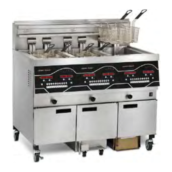
Henny Penny Wendy's Evolution Elite EEE-153 Technical Manual
Electric reduced oil capacity open fryer
Hide thumbs
Also See for Wendy's Evolution Elite EEE-153:
- Technical manual (86 pages) ,
- Operator's manual (70 pages) ,
- Operator's manual (80 pages)
Advertisement
Quick Links
W W e e n n d d y y ' ' s s E E v v o o l l u u t t i i o o n n
E E l l i i t t e e ™ ™ ( ( E E l l e e c c t t r r i i c c ) )
R R e e d d u u c c e e d d O O i i l l C C a a p p a a c c i i t t y y
O O p p e e n n F F r r y y e e r r
FM06-046B
TECHNICAL
MANUAL
TECHNICAL
MANUAL
EEE-153
EEE-154
EEE-153
EEE-154
Advertisement

Subscribe to Our Youtube Channel
Related Manuals for Henny Penny Wendy's Evolution Elite EEE-153


Summary of Contents for Henny Penny Wendy's Evolution Elite EEE-153
- Page 1 TECHNICAL MANUAL TECHNICAL MANUAL W W e e n n d d y y ’ ’ s s E E v v o o l l u u t t i i o o n n E E l l i i t t e e ™ ™ ( ( E E l l e e c c t t r r i i c c ) ) R R e e d d u u c c e e d d O O i i l l C C a a p p a a c c i i t t y y EEE-153 O O p p e e n n F F r r y y e e r r...
- Page 3 Table of Contents Safety and Compliance....................v Chapter 1 Troubleshooting ....................1 1.1 Introduction ......................1 1.2 Troubleshooting .....................1 1.3 Error Codes ......................4 Chapter 2 Info & Filter Button Stats ..................7 2.1 Info Button Stats ....................7 2.2 Filter Button Stats ....................7 Chapter 3 Information Mode ....................9 3.1 Information Mode Details ..................10 3.1.1 1.
- Page 4 5.1.18 SP-18 Energy Save Mode................25 5.1.19 SP-19 Fryer Type ..................25 5.1.20 SP-20 Vat Type ....................25 5.1.21 SP-21 Auto-Lift Enabled ................25 5.1.22 SP-22 Bulk Oil Supply ..................25 5.1.23 SP-23 Bulk Oil Disposal................26 5.1.24 SP-24 Serial Number Log ................26 5.1.25 SP-25 Program Code Change...............26 5.1.26 SP-26 Usage Code Change................26 5.1.27 SP-27 Dispose Requires Code? ..............26 5.1.28 SP-28 Longer Fill Time .................27...
- Page 5 6.11.2 Replacement ....................52 6.12 Solenoid Valves ....................54 6.12.1 Replacement ....................54 6.13 Filter Pump & Motor....................57 6.13.1 Resetting Thermal Overload Switch...............58 6.13.2 Motor Removal ....................58 6.13.3 Replacement Of Pump Motor ................60 6.14 JIB Pump......................60 6.14.1 Replacement ....................60 6.15 Express Filter PC Board ..................62 6.15.1 Replacement ....................62 6.16 Transformers .....................63 6.16.1 Checkout.....................63...
- Page 7 S S a a f f e e t t y y a a n n d d C C o o m m p p l l i i a a n n c c e e The Henny Penny unit has many safety features incorporated. However, the only way to ensure safe operation is to fully understand the proper installation, operation, and maintenance procedures.
- Page 8 SHOCK HAZARD SYMBOLS HOT SURFACE SYMBOLS These are the original version controlled Henny Penny instructions for Wendy’s Evolution Elite Reduced Oil Capacity Electric Open Fryer Model EEE-153 and 154. This manual is available on the Henny Penny Public website (www.hennypenny.com).
- Page 9 boiling and fire due to the reduced flash point of the oil. The oil temperature must never exceed 450⁰ F (230⁰ C). This appliance is not intended for use by persons (including children) with reduced physical, sensory or mental capabilities, or lack of experience and knowledge, unless they have been given supervision or instruction concerning use of the appliance by a person responsible for their safety.
- Page 10 viii...
- Page 11 C C h h a a p p t t e e r r 1 1 T T r r o o u u b b l l e e s s h h o o o o t t i i n n g g 1 1 .
- Page 12 Problem Cause Correction Faulty PC board. Remove and replace control panel. High limit control Reset the high limit by using a small screwdriver or Allen switch tripped. wrench, gently pushing it into the hold in the heating ele- ment hinge; if high limit does not reset, high limit must be replaced.
- Page 13 Problem Cause Correction Improper rinsing Rinse the vat thoroughly to remove any cleaning agent in after cleaning the the vat. vat. Oil will not Drain valve Open valve, force cleaning brush through drain. drain from clogged with vat. crumbs. Drain trough Access the clean-out plug on the sides of the unit (see clogged.
- Page 14 Problem Cause Correction “CHECK Filter pan not Adjust filter pan. PAN” completely engaged. “FILTER Filter pan Find pan and replace. missing. MISSING” Filter pan inter- Adjust filter pan to engage interlock. lock not engaged. “CHANGE Filter pad has not Replace old filter pad with new filter pad with main power FILTER been changed switch turned on.
- Page 15 Display Cause Panel Board Correction “E-10 D” High limit tripped <5 min of Auto Filter “E-10 F” High limit tripped during filter cycle “E-10 M” High limit tripped during melt mode “E-10 Y” High limit tripped <5 min of “YES” “E-15”...
- Page 16 Display Cause Panel Board Correction “E-41” Programming Turn power switch to off, then back to on; if display shows ”E-46” failure. an error code, have the controls re-initialized; if error code persists, have the control board replaced. “E-47” Analog converter Turn power switch off, then back to on;...
- Page 17 C C h h a a p p t t e e r r 2 2 I I n n f f o o & & F F i i l l t t e e r r B B u u t t t t o o n n S S t t a a t t s s NOTE: If no buttons are pressed within 5 seconds in any of stats modes, the controls revert back to normal operation.
- Page 19 NOTE: • Not all Information Mode functions are discussed in this section. To ensure proper operation of fryer, please consult Henny Penny Corp. before changing any of these settings. For more information on these functions, contact Technical Support at 1- 800-417-8405, or 1-937-456-8405.
- Page 20 3 3 . . 1 1 I I n n f f o o r r m m a a t t i i o o n n M M o o d d e e D D e e t t a a i i l l s s 3 3 .
- Page 21 Function Display Example After Complete Cook Cycle *DONE* +6 SEC Difference (%) Between Actual And Pro- ACT/PROG grammed Cook Time 3 3 . . 1 1 . . 3 3 3 3 . . D D a a i i l l y y S S t t a a t t s s The Daily Stats section provides operational information of the fryer for the last 7 days.
- Page 22 3 3 . . 1 1 . . 4 4 4 4 . . O O i i l l S S t t a a t t s s The Oil Stats section provides information of current oil and average of last 4 batches of oil.
- Page 23 Function Display Example Number of times oil discarded (L/R) DISPOSE Total number of cook cycles (L/R) TOT CK Number of cycles stopped before *DONE* QUIT CK Cook Cycles for Product #1 COOK -1- Cook Cycles for Product #2 COOK -2- Cook Cycles for Product #3 COOK -3- Cook Cycles for Product #4...
- Page 24 H = HEAT CONTACTOR - Press product 7 to turn off and on the heat contactor (product 1 turns off and on the safety (primary) contactor for the left vat of a split vat fryer, and product 2 turns off and on the heat contactor). 3 3 .
- Page 25 C C h h a a p p t t e e r r 4 4 P P r r o o d d u u c c t t P P r r o o g g r r a a m m M M o o d d e e This mode allows you to program the following: •...
- Page 26 to it, that LED will be lit. To assign other product buttons to that product, press and hold the product button for 3 seconds and that LED stays lit. To remove a product from a button, press and hold the product button with a lit LED and the LED goes out.
- Page 27 above this setting and slows down at temperatures below this setting. Press the product buttons, or the up or down arrow, to change this value. F F u u l l l l H H e e a a t t 1 1 5 5 ) ) Press the right arrow until “FULL HT”...
- Page 29 C C h h a a p p t t e e r r 5 5 L L e e v v e e l l 2 2 P P r r o o g g r r a a m m m m i i n n g g Used to access the following: •...
- Page 30 S S P P - - 7 7 Idle Mode Enabled - YES or NO S S P P - - 7 7 A A Use “0” for IDLE S S P P - - 7 7 B B Auto Idle Minutes S S P P - - 7 7 C C Idle Set-point Temperature S S P P - - 8 8...
- Page 31 S S P P - - 2 2 8 8 Longer Fill Time Enabled - YES or NO S S P P - - 2 2 9 9 Let User Exit Fill? - YES or NO S S P P - - 3 3 0 0 Skip ‘SKIM’...
- Page 32 With “YES” in the display, press the right arrow and “SP-7A” “USE ‘0’ FOR 2 2 ) ) IDLE” flashes on the left display. Press the up or down arrow to select “YES” or “NO”. If “YES” is selected, an Idle Mode can be programmed for product 0. Press the down arrow and “SP-7B”...
- Page 33 Press the right arrow and “SP-8C” “FILTER LOCKOUT AT...” shows in left 4 4 ) ) display and a value between 100% and 250% shows on right display. Press the up or down arrow to change this value. The lower the value, the sooner the “lockout”...
- Page 34 5 5 . . 1 1 . . 9 9 S S P P - - 9 9 P P o o l l i i s s h h D D u u r r a a t t i i o o n n Press and the release the right arrow until “SP-9 POLISH TIME”...
- Page 35 NOTE: By settings a 2nd language in the controls, 2 languages can now be chosen by pressing the program button during normal operation. One language shows in the right display. Pressing ✓ selects the language in the display. 5 5 . . 1 1 . . 1 1 7 7 S S P P - - 1 1 7 7 2 2 n n d d V V o o l l u u m m e e Press and release the right arrow until “SP-17 2ND VOLUME”...
- Page 36 5 5 . . 1 1 . . 2 2 3 3 S S P P - - 2 2 3 3 B B u u l l k k O O i i l l D D i i s s p p o o s s a a l l Press and release the right arrow until “SP-23 BULK OIL DISPOSE?”...
- Page 37 Press the up or down arrow to choose “YES” or “NO”. If set to “YES”, code 1, 2, 2 2 ) ) 3, must be entered to discard the oil from the vat using the Dispose Mode. 5 5 . . 1 1 . . 2 2 8 8 S S P P - - 2 2 8 8 L L o o n n g g e e r r F F i i l l l l T T i i m m e e Press and release the right arrow until ”SP-28 LONGER FILL TIME ENABLED?”...
- Page 38 C C o o n n t t r r o o l l M M o o d d e e s s The Data Logging, Heat Control, Tech, Stat and Filter Control Modes are advanced diagnostic and program modes, mainly for Henny Penny use only. For more information on these modes, contact the Service Department at 1-800-417-8405 or 1- 937-456-8405.
- Page 39 • T-25 Total Initialization NOTE: Not all Tech Mode functions are discussed in this section. To ensure proper operation of fryer, please consult Henny Penny Corp. before changing any of these settings. For more information on these functions, contact the Service Department at 1-800-417-8405, or 1-937-456-8405.
- Page 40 5 5 . . 5 5 . . 1 1 T T - - 1 1 S S o o f f t t w w a a r r e e • Press product button 1 to view HP Part No. of eprom. •...
- Page 41 H = HEAT CONTACTOR - Press product button 7 to turn off and on the heat contactor. (Product button 1 turns off and on the safety (primary) contactor for the left vat of a split vat fryer, and product button 2 turns off and on the heat contactor.) 5 5 .
- Page 42 R = RTI DT = Discard Tank Ex = E-Stop pressed Px = drain pan is missing Jx = JIB oil level is low Rx = RTI System NOT Detected DTx = tank full Press the down arrow button and “OUT F_J_” and “N_DI_oJF_” shows in the 1 1 6 6 ) ) displays.
- Page 43 • ST-3 Left Vat Melt Cycle Hours • ST-4 Left Vat Cook Cycle Hours • ST-5 Left Vat Idle Hours • ST-6 Right Vat Melt Cycle Hours • ST-7 Right Vat Cook Cycle Hours • ST-8 Right Vat Idle Hours •...
- Page 45 C C h h a a p p t t e e r r 6 6 M M a a i i n n t t e e n n a a n n c c e e 6 6 . . 1 1 I I n n t t r r o o d d u u c c t t i i o o n n This section provides checkout and replacement procedures, for various parts of the fryer.
- Page 46 6 6 . . 4 4 C C o o n n t t r r o o l l P P a a n n e e l l & & M M e e n n u u C C a a r r d d R R e e p p l l a a c c e e m m e e n n t t Should the control panel become inoperative, or the menu card needs changed, follow these instructions: Remove electrical power supplied to the vat.
- Page 47 Unplug the connectors going to the control board. 5 5 ) ) Install a new control panel in reverse order. 6 6 ) ) 6 6 . . 5 5 H H i i g g h h T T e e m m p p e e r r a a t t u u r r e e L L i i m m i i t t C C o o n n t t r r o o l l This is a safety, manual reset control, which senses the temperature of the oil.
- Page 48 6 6 . . 5 5 . . 1 1 C C h h e e c c k k o o u u t t T T o o a a v v o o i i d d e e l l e e c c t t r r i i c c a a l l s s h h o o c c k k o o r r p p r r o o p p e e r r t t y y d d a a m m a a g g e e , , m m o o v v e e t t h h e e p p o o w w e e r r s s w w i i t t c c h h t t o o o o f f f f a a n n d d d d i i s s c c o o n n n n e e c c t t m m a a i i n n c c i i r r c c u u i i t t b b r r e e a a k k e e r r , , o o r r u u n n p p l l u u g g c c o o r r d d a a t t w w a a l l l l r r e e c c e e p p t t a a c c l l e e .
- Page 49 Using a crosshead screwdriver, remove the 2 screws securing the high limit to 3 3 ) ) the bracket. Use the lift tool and lift the hinged element from the vat. 4 4 ) ) I I f f m m a a i i n n t t e e n n a a n n c c e e p p r r o o c c e e d d u u r r e e s s a a r r e e n n o o t t f f o o l l l l o o w w e e d d c c o o r r r r e e c c t t l l y y , , i i n n j j u u r r i i e e s s a a n n d d / / o o r r p p r r o o p p e e r r t t y y d d a a m m a a g g e e c c o o u u l l d d r r e e s s u u l l t t .
- Page 50 Pull out on the drain valve knob and drain the oil from the vat. 6 6 ) ) While holding the top-side capillary bracket, use a crosshead screwdriver and 7 7 ) ) remove the screws securing the capillary bulb to the lower element bracket. Remove both front and rear capillary brackets.
- Page 51 Remove high limit bulb from element and carefully straighten the capillary tube 9 9 ) ) and pull the high limit control from the rear of the unit. NOTICE • It’s important not to damage the capillary bulb when removing or installing the high limit from the unit.
- Page 52 Slide bracket and high limit assembly into place, making sure a 1/8” (2-3mm) 1 1 1 1 ) ) gap remains between the red high limit button and the reset place, and then secure with the 2 acorn nuts removed in step 3. Carefully slide capillary bulb up through the element, from the rear of the 1 1 2 2 ) ) elements.
- Page 53 6 6 . . 6 6 B B r r e e a a k k e e r r s s There are 4 breaker on the electric fryers. To reset the breaker, open the left door and locate breakers behind drain knob plate. Push on the plunger on the breaker to reset. S S H H O O C C K K H H A A Z Z A A R R D D : : T T o o a a v v o o i i d d e e l l e e c c t t r r i i c c a a l l s s h h o o c c k k o o r r p p r r o o p p e e r r t t y y d d a a m m a a g g e e , , m m o o v v e e t t h h e e p p o o w w e e r r s s w w i i t t c c h h t t o o o o f f f f a a n n d d d d i i s s c c o o n n n n e e c c t t m m a a i i n n c c i i r r c c u u i i t t b b r r e e a a k k e e r r , , o o r r u u n n p p l l u u g g...
- Page 54 6 6 . . 7 7 M M a a i i n n P P o o w w e e r r S S w w i i t t c c h h This is a covered rocker switch, which in the on position, sends power to all the controls and filter motor.
- Page 55 6 6 . . 8 8 T T e e m m p p e e r r a a t t u u r r e e P P r r o o b b e e R R e e p p l l a a c c e e m m e e n n t t The temperature probe relays the actual shortening temperature to the control.
- Page 56 Pull the connector from the panel and using a multimeter, take an ohm reading 3 3 ) ) on the appropriate oil temp pins. If ohm reading is significantly different than the chart, continue with replacement instructions. 6 6 . . 8 8 . . 2 2 R R e e p p l l a a c c e e m m e e n n t t Pull out on the drain valve knob and drain the oil from the vat.
- Page 57 Locate temperature probe through pot wall. 5 5 ) ) E E x x c c e e s s s s f f o o r r c c e e w w i i l l l l d d a a m m a a g g e e t t e e m m p p e e r r a a t t u u r r e e p p r r o o b b e e .
- Page 58 Lower element back into vat and close drain. Fill vat by pressing and holding the 1 1 1 1 ) ) filter button until “*FILTER* *MENU*” shows in the display. Then once “1. EXPRESS FILTER” shows in the display, press the right arrow 4 times until “5. FILL FROM PAN”...
- Page 59 6 6 . . 1 1 0 0 . . 2 2 R R e e p p l l a a c c e e m m e e n n t t Remove the rear panel (9 screws). 1 1 ) ) Pull the wires from the switch.
- Page 60 Reassemble with new switch, making sure the plate pushes in the switch 4 4 ) ) plunger, activating the switch, and then reconnect power to the fryer. 6 6 . . 1 1 1 1 C C o o n n t t a a c c t t o o r r s s The Evolution Elite®...
- Page 61 6 6 . . 1 1 1 1 . . 1 1 C C h h e e c c k k o o u u t t Remove electrical power supplied to the fryer. 1 1 ) ) S S H H O O C C K K H H A A Z Z A A R R D D : : T T o o a a v v o o i i d d e e l l e e c c t t r r i i c c a a l l s s h h o o c c k k o o r r p p r r o o p p e e r r t t y y d d a a m m a a g g e e , , m m o o v v e e t t h h e e p p o o w w e e r r s s w w i i t t c c h h t t o o o o f f f f a a n n d d d d i i s s c c o o n n n n e e c c t t m m a a i i n n c c i i r r c c u u i i t t b b r r e e a a k k e e r r , , o o r r u u n n p p l l u u g g c c o o r r d d a a t t w w a a l l l l r r e e c c e e p p t t a a c c l l e e .
- Page 62 S S H H O O C C K K H H A A Z Z A A R R D D : : T T o o a a v v o o i i d d e e l l e e c c t t r r i i c c a a l l s s h h o o c c k k o o r r p p r r o o p p e e r r t t y y d d a a m m a a g g e e , , m m a a k k e e c c o o n n n n e e c c t t i i o o n n s s b b e e f f o o r r e e a a p p p p l l y y i i n n g g p p o o w w e e r r , , t t a a k k e e r r e e a a d d i i n n g g , , a a n n d d r r e e m m o o v v e e p p o o w w e e r r b b e e f f o o r r e e r r e e m m o o v v i i n n g g m m e e t t e e r r l l e e a a d d s s .
- Page 63 Using a 3/8” wrench or socket, remove the 2 mounting nuts on the base plate of 2 2 ) ) the contactor being replaced and remove contactor. When replacing the heat contactor, slide it from the mounting rail. 3 3 ) ) Install new contactor in reverse order.
- Page 64 6 6 . . 1 1 2 2 S S o o l l e e n n o o i i d d V V a a l l v v e e s s Each vat has a solenoid plumbed-into the oil return lines. They are normally closed, but open when power is supplied, such as, the controls are filling the vats.
- Page 65 Using a 1 inch wrench, loosen the fitting on the right side of the solenoid. 4 4 ) ) Pull the elbow away from the 1 inch nut, and using a 1-1/16 inch wrench or 5 5 ) ) adjustable wrench, hold the solenoid in place while using another wrench to remove the elbow from the solenoid.
- Page 66 Remove the conduit from the fryer and pull the coil assembly from the fryer. 7 7 ) ) Disconnect conduit at coil. 8 8 ) ) Thread the wires of the new solenoid through the conduit and reattach the 9 9 ) ) conduit to the fryer.
- Page 67 6 6 . . 1 1 3 3 F F i i l l t t e e r r P P u u m m p p & & M M o o t t o o r r The 2 most common causes for a fryer not to pump oil are that the pump is clogged, or the thermal overload switch has been tripped on the motor.
- Page 68 There is an indicator on the side of the 2 halves of the pump, this mark must be together. NOTICE: A small amount of grease might be needed to hold the bottom roller into place until cover plate is put on. Make sure O-ring is in proper position on plate.
- Page 69 Using a 1 inch wrench, loosen the rear pump fitting. 4 4 ) ) Using crosshead screwdriver, remove the rear cover from motor, exposing the 5 5 ) ) wires. Loosen the conduit clamp and pull the wires through the conduit clamp. 6 6 ) ) Using a 7/16 inch wrench, remove the 4 bolts securing the motor to the motor 7 7 ) )
- Page 70 Pull pump and motor out from front of fryer across the JIB shelf. 8 8 ) ) 6 6 . . 1 1 3 3 . . 3 3 R R e e p p l l a a c c e e m m e e n n t t O O f f P P u u m m p p M M o o t t o o r r Using a 1/2 inch wrench, remove the 2 bolts securing the pump to the motor and 1 1 ) ) pull the pump from the motor.
- Page 71 Remove the 4 bolts securing the bottom of pump. 4 4 ) ) Disconnect the wires in the rear of the pump and pull assembly from fryer. 5 5 ) ) Pull fittings from faulty pump and attach the fittings to the new pump in the same 6 6 ) ) orientation.
- Page 72 6 6 . . 1 1 5 5 E E x x p p r r e e s s s s F F i i l l t t e e r r P P C C B B o o a a r r d d This electronic board controls the Automatic Intermittent Filtering process.
- Page 73 6 6 . . 1 1 6 6 T T r r a a n n s s f f o o r r m m e e r r s s Both the Express Filter transformer and the control transformer are the same part number.
- Page 74 Figure 6-2 Control Transformer Connector Test Points Results From pin 1 to 2 24 VAC From pin 4 to 5 240 VAC From pin 3 to 5 208 VAC 6 6 . . 1 1 6 6 . . 2 2 R R e e p p l l a a c c e e m m e e n n t t Disconnect power and using a 5/16 inch socket, remove the nuts securing the 1 1 ) ) transformer and pull the transformer from unit.
- Page 75 Figure 6-4 Control Transformer Replace transformer in reverse order. 2 2 ) ) 6 6 . . 1 1 7 7 F F i i l l t t e e r r M M o o t t o o r r R R e e l l a a y y This component is located behind the left control panel and regulates voltage to the filter motor.
- Page 76 Install new relay in reverse order. 4 4 ) ) 6 6 . . 1 1 8 8 D D r r a a i i n n P P a a n n S S w w i i t t c c h h This switch closes when the drain pan is pushed properly in place under the fryer.
- Page 77 Using a Phillips-Head screwdriver, remove the screws securing the switch to the 3 3 ) ) bracket and remove switch from bracket. Label and remove wires from switch. 4 4 ) ) Replace faulty switch, placing wires on new switch on the normally open(1) and 5 5 ) ) common(2) terminals.
- Page 78 6 6 . . 1 1 9 9 F F i i l l t t e e r r B B e e a a c c o o n n ® ® 6 6 . . 1 1 9 9 . . 1 1 R R e e p p l l a a c c e e m m e e n n t t S S H H O O C C K K H H A A Z Z A A R R D D : : T T o o a a v v o o i i d d e e l l e e c c t t r r i i c c a a l l s s h h o o c c k k o o r r p p r r o o p p e e r r t t y y d d a a m m a a g g e e , , m m o o v v e e t t h h e e p p o o w w e e r r s s w w i i t t c c h h t t o o o o f f f f a a n n d d d d i i s s c c o o n n n n e e c c t t m m a a i i n n c c i i r r c c u u i i t t b b r r e e a a k k e e r r , , o o r r u u n n p p l l u u g g...
- Page 79 Connect new light wires using wirenuts, and install light in reverse order. 4 4 ) ) Restore power to the unit. 5 5 ) ) 6 6 . . 2 2 0 0 O O i i l l L L e e v v e e l l P P r r o o b b e e s s The oil level probes monitor the oil level by temperature differences.
- Page 80 Resist- Resist- Resist- ance ance ance °F °C Ohms °F °C Ohms °F °C Ohms 32.22 1125.32 104.44 1401.84 182.22 1692.86 37.78 1146.81 110.00 1422.86 185.00 1703.13 43.33 1168.26 115.56 1443.85 187.78 1713.38 48.89 1189.67 121.11 1464.79 193.33 1733.87 54.44 1211.05 126.67 1485.71...
- Page 81 Place the nut and new ferrule on the new temperature probe and insert the 4 4 ) ) temperature probe into the compression fitting. Locate temperature probe through pot wall. 5 5 ) ) Place gauge against pot wall as shows in Figure 6-1 Probe Assembly Install , 6 6 ) ) page...
- Page 82 right arrow 4 times until “5.FILL FROM PAN” shows in the display. Press ✓ and “PUMP” “EXIT” shows in the display. Press ✓ again, and oil fills vat. Once vat is full, press X X twice to return to normal operation. 6 6 .
- Page 83 Remove wires from switch and place on new switch, placing them on the 4 4 ) ) normally open and common terminals. Install new switch in reverse order. 5 5 ) ) 6 6 . . 2 2 2 2 T T i i m m e e D D e e l l a a y y R R e e l l a a y y s s ( ( E E E E E E - - 1 1 5 5 3 3 & & E E E E E E - - 1 1 5 5 4 4 ) ) This relay is located behind the left control panel, and transfers electrical power to the control to the right if power is lost in the left vat.
- Page 85 W W i i r r i i n n g g D D i i a a g g r r a a m m...
- Page 87 blank page...
- Page 88 H H e e n n n n y y P P e e n n n n y y C C o o r r p p o o r r a a t t i i o o n n P P .
Need help?
Do you have a question about the Wendy's Evolution Elite EEE-153 and is the answer not in the manual?
Questions and answers