Table of Contents
Advertisement
Quick Links
Advertisement
Table of Contents

Related Manuals for Rockwell Automation Allen-Bradley PowerFlex 20-COMM-B


Summary of Contents for Rockwell Automation Allen-Bradley PowerFlex 20-COMM-B
- Page 1 BACnet MS/TP Adapter 20-COMM-B FRN 1.xxx User Manual...
- Page 2 In no event will Rockwell Automation, Inc. be responsible or liable for indirect or consequential damages resulting from the use or application of this equipment.
- Page 3 Summary of Changes The information below summarizes the changes made to this manual since its last release (May 2006): Description of Changes Page(s) In the “Quick Start” section: • In Step 4, removed connecting the adapter to the network. • In Step 5, added two new sub-steps (B and C). •...
- Page 4 soc-ii Summary of Changes...
-
Page 5: Table Of Contents
Related Documentation ......P-1 Rockwell Automation Support......P-2 Conventions Used in This Manual . - Page 6 Table of Contents Chapter 5 Troubleshooting Understanding the Status Indicators ....5-1 PORT Status Indicator ......5-2 MOD Status Indicator .
-
Page 7: Preface
Preface About This Manual Topic Page Related Documentation Rockwell Automation Support Conventions Used in This Manual Related Documentation For: Refer to: Publication DriveExplorer™ http://www.ab.com/drives/driveexplorer, and — DriveExplorer online help (installed with the software) DriveTools™ SP (includes http://www.ab.com/drives/drivetools, and — DriveExecutive™) -
Page 8: Rockwell Automation Support
• Product technical training • Warranty support • Support service agreements Technical Product Assistance If you need to contact Rockwell Automation, Inc. for technical assistance, please review the information in Chapter Troubleshooting first. If you still have questions, then access the Allen-Bradley Technical Support web site at www.ab.com/support/abdrives. -
Page 9: Getting Started
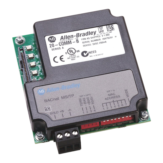
Chapter Getting Started The 20-COMM-B BACnet MS/TP adapter is a communication option intended for installation into a PowerFlex 7-Class drive. It can also be used with other Allen-Bradley products that support an internal DPI ™ (Drive Peripheral Interface) adapter, such as the DPI External Comms Kit (20-XCOMM-DC-BASE). -
Page 10: Features
Getting Started Features The 20-COMM-B BACnet MS/TP adapter features the following: • The adapter is normally mounted in the PowerFlex 7-Class drive. It can also be installed in a DPI External Comms Kit Important: Due to inherent operating limitations, the adapter cannot be used with the kit’s optional I/O board. -
Page 11: Compatible Products
Getting Started Compatible Products The 20-COMM-B BACnet MS/TP adapter is compatible with most Allen-Bradley PowerFlex 7-Class (Architecture-Class) drives and other products that support DPI. DPI is a second generation peripheral communication interface and functional enhancement to SCANport. At the time of publication, compatible products include: •... -
Page 12: Safety Precautions
Getting Started Safety Precautions Please read the following safety precautions carefully. ATTENTION: Risk of injury or death exists. The PowerFlex drive may contain high voltages that can cause injury or death. Remove power from the PowerFlex drive, and then verify power has been discharged before installing or removing an adapter. - Page 13 There are many variables and requirements with any application. Rockwell Automation, Inc. does not assume responsibility or liability (to include intellectual property liability) for actual use of the examples shown in this publication.
-
Page 14: Quick Start
Getting Started Quick Start This section is provided to help experienced users quickly start using the adapter. If you are unsure how to complete a step, refer to the referenced chapter. Step Action Refer to… Review the safety precautions for the adapter. Throughout this manual Verify that the PowerFlex drive is properly installed. -
Page 15: Status Indicators
Getting Started Status Indicators The adapter uses four status indicators to report its operating status. They can be viewed on the adapter or through the drive cover (Figure 1.2). Figure 1.2 Status Indicators (location on drive may vary) ➊ ➊ ➋... - Page 16 Getting Started Notes:...
-
Page 17: Installing The Adapter
Chapter Installing the Adapter Chapter 2 provides instructions for installing the adapter in a PowerFlex 7-Class drive. This adapter can also be installed in a DPI External Comms Kit. In this case, refer to the 20-XCOMM-DC-BASE Installation Instructions (Publication No. 20COMM-IN001…) supplied with the kit. Topic Page Preparing for an Installation... -
Page 18: Address
Installing the Adapter Setting the MAC Address Set the MAC address using the MAC Address switches (Figure 2.1). Refer to Table 2.A for specific MAC address switch settings. Important: Each node on the network must have a unique MAC address. The MAC address must be set before power is applied because the adapter uses the MAC address it detects when it first receives power. - Page 19 Installing the Adapter Table 2.A MAC Address Switch Settings (UP = 1 = OPEN) (Continued) Switch Setting Switch Setting Address Address SW1 SW2 SW3 SW4 SW5 SW6 SW7 SW1 SW2 SW3 SW4 SW5 SW6 SW7...
- Page 20 Installing the Adapter Table 2.A MAC Address Switch Settings (UP = 1 = OPEN) (Continued) Switch Setting Switch Setting Address Address SW1 SW2 SW3 SW4 SW5 SW6 SW7 SW1 SW2 SW3 SW4 SW5 SW6 SW7 Setting the TERM, -BIAS, and +BIAS Switches The adapter’s TERM, -BIAS, and +BIAS switches (Figure 2.2) are used...
- Page 21 Installing the Adapter Network with PowerFlex Drives at Starting and/or Ending Nodes For a network with PowerFlex drives at the starting and/or ending nodes (Figure 2.3), set their 20-COMM-B adapter’s TERM, -BIAS, and +BIAS switches to the “Down” (On) position. All other PowerFlex drive network nodes must have these switches set to the “Up”...
-
Page 22: Connecting The Adapter To The Drive
Installing the Adapter Connecting the Adapter to the Drive 1. Remove power from the drive. 2. Use static control precautions, and remove or open the drive cover. 3. Connect the Internal Interface cable to the DPI port on the drive and then to the DPI connector on the adapter. - Page 23 Installing the Adapter 4. Secure and ground the adapter to the drive by doing the following: – On a PowerFlex 70 drive, fold the Internal Interface cable behind the adapter and mount the adapter on the drive using the four captive screws.
-
Page 24: Applying Power
Installing the Adapter Applying Power ATTENTION: Risk of equipment damage, injury, or death exists. Unpredictable operation may occur if you fail to verify that parameter settings are compatible with your application. Verify that settings are compatible with your application before applying power to the drive. - Page 25 Installing the Adapter Table 2.B Drive and Adapter Start-Up Status Indications Item Name Color State Description Drive STS Indicator ➊ Green Flashing Drive ready but not running, and no faults are present. (Status) Steady Drive running, no faults are present. Yellow Flashing, An inhibit condition exists –...
-
Page 26: Connecting The Drive/Adapter To The Network
2-10 Installing the Adapter Configuring/Verifying Key Drive Parameters The PowerFlex 7-Class drive can be separately configured for the control and reference functions in various combinations. For example, you could set the drive to have its control come from a peripheral or terminal block with the reference coming from the BACnet MS/TP network. - Page 27 Installing the Adapter 2-11 Figure 2.8 Typical Network Terminal Connections Node 1 Node 2 Node "n" Terminal Signal Function SHLD Termination Shield Termination Signal B TxRxD+ Signal A TxRxD- 5. Insert the 3-pin linear plug into the mating adapter socket. 6.
- Page 28 2-12 Installing the Adapter Notes:...
-
Page 29: Configuring The Adapter
Chapter Configuring the Adapter Chapter 3 provides instructions and information for setting the parameters in the adapter. Topic Page Configuration Tools Using the PowerFlex 7-Class HIM Setting the Device Instance Number Setting a Comm Loss Action Setting the Comm Loss Time Setting the Baud Rate Resetting the Adapter Viewing the Adapter Configuration... -
Page 30: Using The Powerflex 7-Class Him
Configuring the Adapter Using the PowerFlex 7-Class HIM If your drive has either an LED or LCD HIM (Human Interface Module), you can use it to access parameters in the adapter as shown below. It is recommended that you read through the steps for your HIM before performing the sequence. -
Page 31: Setting The Device Instance Number
Configuring the Adapter Setting the Device Instance Number While there are many ways to implement Device Instance and network strategies, the example shown in Figure 3.1 illustrates one logical approach. In this example, two individual Floor Level Networks are connected to the Building Level Network through a router which allows devices on each network to share the same MAC address. - Page 32 Configuring the Adapter 1. Set the value of Parameter 11 - [Device Instance] to a unique Device Instance Number. Figure 3.2 Device Instance Screen on an LCD HIM Default = 160000 Port 5 Device 20-COMM-B Parameter #: 11 Device Instance 160000 2.
-
Page 33: Setting A Comm Loss Action
Configuring the Adapter Setting a Comm Loss Action By default, when communications are disrupted (for example, a cable is disconnected), the drive responds by faulting if it is using I/O from the network. You can configure a different response to communication disruptions using Parameter 02 - [Comm Loss Action]. -
Page 34: Setting The Comm Loss Time
Configuring the Adapter To set the fault configuration parameters If you set Parameter 02 - [Comm Loss Action] to “Send Flt Cfg,” the values in the following parameters are sent to the drive after a communications fault occurs. You must set these parameters to values required by your application. -
Page 35: Setting The Baud Rate
Configuring the Adapter Setting the Baud Rate The value of Parameter 06 - [Baud Rate Cfg] determines the baud rate used by the adapter. The Autobaud setting will detect the baud rate used on the network if another device is setting the baud rate. Your application may require a different setting. -
Page 36: Viewing The Adapter Configuration
Configuring the Adapter When you enter 1 = Reset Module, the adapter will be immediately reset. When you enter 2 = Set Defaults, the adapter will set all adapter parameters to their factory-default settings. After performing a Set Defaults, enter 1 = Reset Module so that the new values take effect. The value of this parameter will be restored to 0 = Ready after the adapter is reset. -
Page 37: Using Bacnet Objects
Chapter Using BACnet Objects Chapter 4 provides information about controlling a compatible PowerFlex 7-Class drive using BACnet objects. Topic Page Understanding BACnet Objects Basic Drive Operation on the Network Supported BACnet Objects Understanding BACnet Objects BACnet nodes are controlled and monitored by the use of several types of objects. -
Page 38: Basic Drive Operation On The Network
Using BACnet Objects Basic Drive Operation on the Network This section describes how to operate a drive on the network using a combination of BACnet object types for basic control. ATTENTION: Control information written to the adapter by a BACnet controller is volatile. -
Page 39: Supported Bacnet Objects
Using BACnet Objects Supported BACnet Objects The type of drive used on the network determines the specific BACnet objects that are supported. Refer to Table 4.A for descriptions of the BACnet objects and the drives supporting those objects. - Page 40 Using BACnet Objects...
- Page 41 Using BACnet Objects...
- Page 42 Using BACnet Objects...
-
Page 43: Troubleshooting
Chapter Troubleshooting Chapter 5 provides information for diagnosing and troubleshooting potential problems with the adapter and network. Topic Page Understanding the Status Indicators PORT Status Indicator MOD Status Indicator NET A Status Indicator NET B Status Indicator Viewing and Clearing Adapter Diagnostic Items Viewing and Clearing Events Understanding the Status Indicators The adapter has four status indicators. -
Page 44: Port Status Indicator
Orange The adapter is connected to a Connect the adapter to a product that product that does not support supports Allen-Bradley DPI Rockwell Automation DPI communications (for example, a PowerFlex communications. 70 or PowerFlex 700 drive). Flashing The adapter is establishing an No action required. -
Page 45: Mod Status Indicator
Troubleshooting MOD Status Indicator State Cause Corrective Actions • Securely connect the adapter to the drive The adapter is not powered or is not properly connected to using the Internal Interface (ribbon) the drive. cable. • Apply power to the drive (or adapter if mounted in a DPI External Comms Kit). -
Page 46: Net A Status Indicator
Troubleshooting NET A Status Indicator State Cause Corrective Actions • Securely connect the adapter to the drive The adapter is not powered or is not properly connected to using the Internal Interface (ribbon) cable. the network. • Correctly connect the network cable to the adapter’s network connector. -
Page 47: Viewing And Clearing Adapter Diagnostic Items
Troubleshooting Viewing and Clearing Adapter Diagnostic Items The following adapter diagnostic items can be viewed using DriveExplorer (version 3.01 or higher) or DriveExecutive (version 3.01 or higher) software, or an LCD PowerFlex HIM (Diagnostic/Device Items). To view and clear adapter diagnostic items Step Keys Example Screen... - Page 48 Troubleshooting Adapter Diagnostic Items If you encounter unexpected communications problems, diagnostic items can help you or Rockwell Automation personnel troubleshoot the problem. No. Name Description Common Logic The present value of the Common Logic Command being transmitted to the drive by this adapter.
-
Page 49: Viewing And Clearing Events
Troubleshooting Viewing and Clearing Events The adapter maintains an event queue that reports the history of its actions. You can view this event queue using an LCD PowerFlex HIM, DriveExplorer software (3.01 or higher), or DriveExecutive software (3.01 or higher). To view and clear events Step Keys... - Page 50 Troubleshooting Events Many events in the Event queue occur under normal operation. If you encounter unexpected communications problems, the events may help you or Allen-Bradley personnel troubleshoot the problem. The following events may appear in the event queue: Code Event Description No Event Empty event queue entry.
-
Page 51: Specifications
Appendix Specifications Appendix A presents the specifications for the adapter. Topic Page Communications Electrical Mechanical Environmental Regulatory Compliance Communications Network Protocols BACnet MS/TP Data Rates 9600, 19200, 38400 or 76800 baud Drive Protocol Data Rates 125 kbps or 500 kbps Electrical Consumption Drive... -
Page 52: Environmental
Specifications Environmental Temperature Operating -10 to 50°C (14 to 122°F) Storage -40 to 85°C (-40 to 185°F) Relative Humidity 5 to 95% non-condensing Atmosphere Important: The adapter must not be installed in an area where the ambient atmosphere contains volatile or corrosive gas, vapors or dust. -
Page 53: Adapter Parameters
Appendix Adapter Parameters Appendix B provides information about the BACnet MS/TP adapter parameters. Topic Page About Parameter Numbers Parameter List About Parameter Numbers The parameters in the adapter are numbered consecutively. However, depending on which configuration tool you use, they may have different numbers. - Page 54 Adapter Parameters Parameter No. Name and Description Details [Comm Loss Action] Default: 0 = Fault Sets the action that the adapter and drive will take Values: 0 = Fault if the adapter detects that network 1 = Stop communications have been disrupted. This setting 2 = Zero Data is effective only if I/O that controls the drive is 3 = Hold Last...
- Page 55 Adapter Parameters Parameter No. Name and Description Details [Baud Rate Act] Default: 0 = Unknown Displays the baud rate (kilobits per second) Values: 0 = Unknown actually used by the adapter. 1 = 9600 kbps 2 = 19200 kbps 3 = 38400 kbps 4 = 76800 kbps Type: Read Only...
- Page 56 Adapter Parameters Notes:...
-
Page 57: Protocol Implementation Conformance Statement
Appendix Protocol Implementation Conformance Statement (PICS) Date: March 27, 2006 Vendor Name: Rockwell Automation Product Name: 20-COMM-B Product Model Number: 20-COMM-B Applications Software Version: 3.003 Firmware Revision: 1.001 BACnet Protocol Revision: 2 Product Description DPI to BACnet MS/TP communication adapter for PowerFlex 7-Class... -
Page 58: Standard Object Types Supported
Protocol Implementation Conformance Statement (PICS) Standard Object Types Supported The table below lists the object types supported by the 20-COMM-B. Dynamic object creation and deletion is not supported. The property access rules use the following key: R = Read Only: the property is supported for this object type W = Read/Write: the property is supported for this object type C = Commandable: the property is supported for this object type Analog... -
Page 59: Data Link Layer Options
Protocol Implementation Conformance Statement (PICS) Data Link Layer Options BACnet IP, (Annex J) BACnet IP, (Annex J), Foreign Device ISO 8802-3, Ethernet (Clause 7) ANSI/ATA 878.1, 2.5 Mb. ARCNET (Clause 8) ANSI/ATA 878.1, RS-485 ARCNET (Clause 8), baud rate(s) MS/TP master (Clause 9), baud rate(s): 9600, 19200, 38400, 76800 MS/TP slave (Clause 9), baud rate(s): Point-To-Point, EIA 232 (Clause 10), baud rate(s): Point-To-Point, modem (Clause 10), baud rate(s):... - Page 60 Protocol Implementation Conformance Statement (PICS) Notes:...
-
Page 61: Routing Capability For Networked Drives
Appendix Routing Capability for Networked Drives Appendix D provides information about the unique routing capability for up to 127 PowerFlex 7-Class drives on a BACnet MS/TP network when using the DriveExplorer (Full version only) drive software tool. First, configure the 20-COMM-B adapter in each networked drive using the procedures described in Chapter 2. - Page 62 Routing Capability for Networked Drives Notes:...
-
Page 63: Glossary
Glossary Adapter Devices such as drives, controllers, and computers usually require an adapter to provide a communication interface between them and a network such as BACnet MS/TP. An adapter reads data on the network and transmits it to the connected device. It also reads data in the device and transmits it to the network. - Page 64 Glossary-2 DPI Peripheral A device that provides an interface between DPI and a network or user. Peripheral devices are also referred to as “adapters” and “modules.” The 20-COMM-B, 1203-SSS or 1203-USB converter, and PowerFlex 7-Class HIMs (20-HIM-xxx) are examples of DPI peripherals. DPI Product A device that uses the DPI communications interface to communicate with one or more peripheral devices.
- Page 65 Glossary-3 user-defined fault configuration. The user sets the data that is sent to the drive using specific fault configuration parameters in the adapter. When a fault action parameter is set to use the fault configuration data and a fault occurs, the data from these parameters is sent as the Logic Command and Reference.
- Page 66 Glossary-4 from the adapter to the network. The definitions of the bits in this word depend on the drive. MAC Address Each device on a network must have a unique MAC address to identify it. On BACnet MS/TP networks, devices can have MAC addresses between 0 and 127 if the network is set up to accommodate that number of devices.
- Page 67 Glossary-5 Status Indicators Status indicators are LEDs that are used to report the status of the adapter, network, and drive. They are on the adapter and can be viewed on the front cover of the drive when the drive is powered. Type 0 Control When transmitting I/O, the adapter can use different types of messages for control.
- Page 68 Glossary-6...
-
Page 69: Index
Index Numerics 3-pin linear plug, 2-11 cables DPI Internal Interface, 2-6 network, 2-11 required for installation, 1-3 adapter Comm Loss Action parameter, B-2 applying power, 2-8 Comm Loss Time parameter, B-2 commissioning, 2-1 commissioning the adapter, 2-1 compatible products, 1-3 compatible products, 1-3 components, 1-1 components of the adapter, 1-1... - Page 70 Index-2 EDS (Electronic Data Sheet) files I/O data, G-3 definition, G-2 installation web site, G-2 applying power to the adapter, 2-8 EEPROM, see Non-Volatile Storage connecting to the drive, 2-6 (NVS) connecting to the network, 2-10 preparing for, 2-1 electrical specifications, A-1 Internal Interface cables environmental specifications, A-2 connecting to adapter and drive,...
- Page 71 Index-3 NET B status indicator ribbon cable, see Internal Interface locating, 1-7 cable troubleshooting with, 5-4 routing capability for networked network cable - connecting to 3-pin drives, D-1 plug, 2-11 Non-Volatile Storage (NVS) accessing parameters in, 3-1 definition, G-4 safety precautions, 1-4 specifications for the adapter, A-1 status indicators definition, G-5...
- Page 72 Index-4 web site DriveExecutive software, G-2 DriveExplorer software, G-2 DriveTools SP software, G-2 EDS files, G-2 PowerFlex manuals, P-1 zero data configuring the adapter for, 3-5 definition, G-5...
- Page 73 Index-5 Notes:...
- Page 74 Index-6 Notes:...
- Page 76 Europe/Middle East/Africa: Rockwell Automation, Vorstlaan/Boulevard du Souverain 36, 1170 Brussels, Belgium, Tel: (32) 2 663 0600, Fax: (32) 2 663 0640 Asia Pacific: Rockwell Automation, Level 14, Core F, Cyberport 3, 100 Cyberport Road, Hong Kong, Tel: (852) 2887 4788, Fax: (852) 2508 1846 Publication 20COMM-UM013C-EN-P –...
Need help?
Do you have a question about the Allen-Bradley PowerFlex 20-COMM-B and is the answer not in the manual?
Questions and answers