
Related Manuals for Rockwell Automation Allen-Bradley 20-COMM-H


Summary of Contents for Rockwell Automation Allen-Bradley 20-COMM-H
- Page 1 20-COMM-H RS-485 HVAC Adapter Firmware Version 2.xxx Modbus RTU Metasys N2 Siemens Building Technologies P1 FLN User Manual...
- Page 2 In no event will Rockwell Automation, Inc. be responsible or liable for indirect or consequential damages resulting from the use or application of this equipment.
- Page 3 Summary of Changes The information below summarizes the changes made to this manual since its last release (March 2004): Description of Changes Page Reformatted document from half size (5.5 x 8.5 in.) to full size (8.5 x 11 in.) Throughout manual Added SMC Flex to the list of compatible products, and Metasys N2 is compatible with PowerFlex 700VC drive.
- Page 4 soc-ii Summary of Changes 20-COMM-H RS-485 HVAC Adapter User Manual Publication 20COMM-UM009D-EN-P...
-
Page 5: Table Of Contents
Rockwell Automation Support ........ - Page 6 Table of Contents Chapter 6 Using Siemens Building Technologies P1 FLN Understanding Siemens Building Technologies P1 FLN ......6-1 Using the P1 FLN Point Map for I/O .
-
Page 7: Preface
To order paper copies of technical documentation, contact your local Rockwell Automation distributor or sales representative. To find your local Rockwell Automation distributor or sales representative, visit www.rockwellautomation.com/locations. For information such as firmware updates or answers to drive-related questions, go to the Drives Service & Support web site at www.ab.com/... -
Page 8: Rockwell Automation Support
About This Manual Rockwell Automation Rockwell Automation, Inc. offers support services worldwide, with over 75 sales/support offices, over 500 authorized distributors, and over 250 Support authorized systems integrators located through the United States alone. In addition, Rockwell Automation, Inc. representatives are in every major country in the world. -
Page 9: Components
Chapter Getting Started The adapter is a communication option intended for installation into a PowerFlex 7-Class drive. It can also be used with other Allen-Bradley products that support a DPI™ (Drive Peripheral Interface) adapter. Topic Page Components Features Compatible Products Required Equipment Safety Precautions Quick Start... -
Page 10: Features
Getting Started Features The adapter features include: • Typical mounting in a PowerFlex 7-Class drive using captive screws to secure and ground the adapter to the drive. • Compatibility with various configuration tools to configure the adapter and connected drive. The tools include the PowerFlex HIM on the drive, and drive-configuration software such as DriveExplorer (version 2.01 or higher) or DriveExecutive (version 3.01 or higher). -
Page 11: Required Equipment
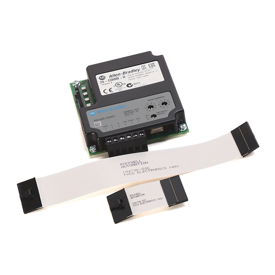
Getting Started Required Equipment Equipment Shipped with the Adapter When you unpack the adapter, verify that the package includes: One adapter A 2.54 cm (1 in.) and a 15.24 cm (6 in.) Internal Interface cable (only one cable is needed to connect the adapter to the drive) User-Supplied Equipment To install and configure the adapter, you must supply: A small flathead screwdriver... - Page 12 There are many variables and requirements with any application. Rockwell Automation, Inc. does not assume responsibility or liability (to include intellectual property liability) for actual use of the examples shown in this publication.
-
Page 13: Quick Start
Getting Started Quick Start This section is provided to help experienced users quickly start using the adapter. If you are unsure how to complete a step, refer to the referenced chapter. Step Action Refer to… Review the safety precautions for the adapter. Throughout This Manual Verify that the PowerFlex drive is properly installed. -
Page 14: Status Indicators
Getting Started Status Indicators The adapter uses four status indicators to report its operating status. They can be viewed on the adapter or through the drive cover (Figure 1.2). Figure 1.2 Status Indicators (location on drive may vary) Item Name PORT NET A NET B... -
Page 15: Preparing For An Installation
Chapter Installing the Adapter This chapter provides instructions for installing the adapter in a PowerFlex 7-Class drive. Topic Page Preparing for an Installation Commissioning the Adapter Connecting the Adapter to the Drive Connecting the Adapter to the Network Applying Power Preparing for an Installation Before installing the adapter, verify that you have all required equipment. - Page 16 Installing the Adapter 1. Set the adapter’s node address by rotating the node address switches to the desired value for each digit. Important: Each node on the network must have a unique address. Figure 2.1 Setting the Node Address Setting Description 01 –...
-
Page 17: Connecting The Adapter To The Drive
Installing the Adapter Connecting the Adapter to the ATTENTION: Risk of injury or death exists. The PowerFlex Drive drive may contain high voltages that can cause injury or death. Remove power from the drive, and then verify power has been discharged before installing or removing the adapter. - Page 18 Installing the Adapter Figure 2.3 DPI Ports and Internal Interface Cables 20-COMM-H Adapter PowerFlex 70 - All Frames PowerFlex 700 Frames 0 and 1 PowerFlex 700 Frames 2 and Larger PowerFlex 700S Frames 0 and 1 PowerFlex 700S Frames 2 through 6 HIM panel opens to allow access to DPI interface.
- Page 19 Installing the Adapter Figure 2.4 Mounting and Grounding the Adapter Drive 0.9 N•m (8.0 lb•in) Adapter 4 Places Internal Interface Cable folded behind the adapter and in front of the drive. Ground Tab Detail PowerFlex 70 - All Frame Sizes (Adapter mounts in drive.) 0.9 N•m (8.0 lb•in)
-
Page 20: Connecting The Adapter To The Network
Installing the Adapter Connecting the Adapter to ATTENTION: Risk of injury or death exists. The PowerFlex the Network drive may contain high voltages that can cause injury or death. Remove power from the drive, and then verify power has been discharged before installing or removing the adapter. -
Page 21: Applying Power
Installing the Adapter Applying Power ATTENTION: Risk of equipment damage, injury, or death exists. Unpredictable operation may occur if you fail to verify that parameter settings are compatible with your application. Verify that settings are compatible with your application before applying power to the drive. - Page 22 Installing the Adapter Item Name Color State Description Adapter Status Indicators PORT Green Flashing Normal Operation. The adapter is establishing an I/O connection to the drive. It will turn solid green or red. Steady Normal Operation. The adapter is properly connected and communicating with the drive Green Flashing...
-
Page 23: Configuration Tools
Chapter Configuring the Adapter This chapter provides instructions and information for setting the parameters in the adapter. Topic Page Configuration Tools Using the PowerFlex 7-Class HIM Setting the Node Address Setting the Network Data Rate Setting the Network Parity Setting Stop Bits (Modbus RTU only) Setting the I/O Configuration Setting a Network Time-out Setting a Fault Action... -
Page 24: Using The Powerflex 7-Class Him
Configuring the Adapter Using the PowerFlex 7-Class If your drive has either an LED or LCD HIM (Human Interface Module), it can be used to access parameters in the adapter as shown below. It is recommended that you read through the steps for your HIM before performing the sequence. -
Page 25: Setting The Node Address
Configuring the Adapter Setting the Node Address If the Node Address switches on the adapter are set to “00,” the value of Parameter 03 - [Net Addr Cfg] determines the node address. 1. Set the value of Parameter 03 - [Net Addr Cfg] to a unique node address. -
Page 26: Setting The Network Parity
Configuring the Adapter Setting the Network Parity The parity that the adapter uses to verify data integrity varies based on the type of network and your network configuration. Refer to the following table. Network Possible Types of Parity Modbus RTU None, Even, or Odd Metasys N2 None... -
Page 27: Setting The I/O Configuration
Configuring the Adapter Setting the I/O The I/O configuration determines the data that is sent to and from the drive. Logic Command/Status, Reference/Feedback, and Datalinks may be Configuration enabled or disabled. A “1” enables the I/O. A “0” disables the I/O. 1. -
Page 28: Setting A Network Time-Out
Configuring the Adapter Setting a Network Time-out The network timeout sets an interval within which the adapter must communicate with its master. If this time is exceeded, the adapter determines a loss of network communications has occurred and responds with the action specified in Parameter 15 - [Comm Flt Action]. By default, the timeout is set to ten (10) seconds. -
Page 29: Setting A Fault Action
Configuring the Adapter Setting a Fault Action By default, when I/O communications are disrupted (for example, a cable is disconnected), the drive responds by faulting if it is using I/O from the network. You can configure a different response to disrupted I/O communication using Parameter 15 - [Comm Flt Action]. -
Page 30: Resetting The Adapter
Configuring the Adapter Resetting the Adapter Changes to switch settings and some adapter parameters require that you reset the adapter before the new settings take effect. You can reset the adapter by cycling power to the drive or by using Parameter 14 - [Reset Module]. -
Page 31: Viewing The Adapter Status Using Parameters
Configuring the Adapter Viewing the Adapter Status The following parameters provide information about the status of the adapter. You can view these parameters at any time. Using Parameters Parameter Description 04 - [Net Add Act] Displays the actual network address of the adapter. 06 - [Net Rate Act] Displays the network data rate actually used by the adapter. -
Page 32: Flash Updating The Adapter
3-10 Configuring the Adapter Flash Updating the Adapter The adapter can be flash updated over the network or serially through a direct connection from a computer to the drive using a 1203-USB or 1203-SSS serial converter. When flashing over the network, you can use the Allen-Bradley software tool ControlFLASH, the built-in flash capability of DriveExplorer Lite or Full, or the built-in flash capability of DriveExecutive. -
Page 33: Chapter 4 Using Modbus Rtu
Chapter Using Modbus RTU This chapter provides information about controlling a PowerFlex 7-Class drive, setting its Reference, and accessing its parameters through configurable objects when the Modbus RTU network protocol is selected. Topic Page Understanding Modbus RTU Using the Modbus RTU Point Map for I/O Accessing Drive Parameters Using Broadcast Messages 4-12... -
Page 34: Adapter Modbus Register Map
Using Modbus RTU Supported Modbus RTU Commands The adapter supports the Modbus RTU commands listed in Table 4.B. Table 4.B Modbus RTU Commands Supported by RS-485 Adapter Function Code Description Read Coil Status Read Input Status Read Holding Registers Read Input Registers Force Single Coil Write Single Register Diagnostics... - Page 35 Using Modbus RTU Table 4.C Adapter Modbus Register Map (Continued) Modbus Register Function 0x0009 Accel Rate 0x0010 0x0011 Decel Rate 0x0012 0x0013 Reference Select 0x0014 0x0015 0x0016 MOP Decrement Read Product Status Word Bits 1x0001 Ready 1x0002 Active 1x0003 Command Direction 1x0004 Actual Direction 1x0005...
-
Page 36: Using The Modbus Rtu Point Map For I/O
Using Modbus RTU Table 4.C Adapter Modbus Register Map (Continued) Modbus Register Function Write Various Holding Registers 4x0001 Product Logic Command 4x0002 Reference Lo (Bits 0…15 of 32-bit Reference) 4x0003 Reference Hi (Bits 16…31 of 32-bit Reference or whole 16-bit Reference) 4x0004 Parameter # for USER IN1 4x0005... - Page 37 Using Modbus RTU Setting the Logic Command and Reference ATTENTION: Select and use either the “Product Logic Command Discrete Outputs (0x000x)” or the “Product Logic Command Register Output (4x0001)” as a control method, but not both. Conflicts caused from using both methods can result in dangerous operation.
- Page 38 Using Modbus RTU Table 4.E shows that there are 16 discrete points to represent the command word bit by bit. These points can be used only for writing single-bit commands. Table 4.E Logic Command: Discrete Outputs (to Drive from Controller) PowerFlex 70/700 Example Modbus Logic Command...
- Page 39 Using Modbus RTU Table 4.F shows the register outputs. These outputs must be used for writing multi-bit commands and the Reference. Table 4.F Logic Command and Reference: Register Outputs Modbus Address Output Description Values 4x0001 Product Logic Command 16-bit word. Bit definitions for PowerFlex 70/700 drives are in Table 4.E.
- Page 40 Using Modbus RTU Table 4.G Logic Status: Discrete Inputs (to Controller from Drive) (Continued) PowerFlex 70/700 Example Modbus Address Logic Status Bit Description Values 1x0010 Local Control Modbus Address 1x0011 12 11 10 1x0012 0 = Port 0 (TB) 1 = Port 1 0 = Port 2 1 = Port 3 0 = Port 4...
-
Page 41: Accessing Drive Parameters
Using Modbus RTU Accessing Drive Parameters There are two methods for accessing drive parameters: the direct access method and the pointer access method. Direct Access Method You can use Function Code 03 to read and Function Codes 06 (single) and 16 (multiple) to write, to directly access the drive parameters (see Table 4.B on page 4-2). - Page 42 4-10 Using Modbus RTU Figure 4.1 Configurable Input Point Operations Write Single Register (code 06) Controller Adapter Write Multiple Register (code 16) Param# Drive for INx Read Input Registers (code 04) Request Response Data User With the adapter in 16-bit mode, 8 User IN items are available. Table 4.I Configurable Objects Inputs with Adapter in 16-bit Mode Modbus...
- Page 43 Using Modbus RTU 4-11 store the returned 16-bit data. Use both 16-bit data items to make one 32-bit value for drive parameter 12. Writing Parameter Values ATTENTION: Risk of equipment damage exists. If configurable output points are programmed to write parameter data to Non-Volatile Storage (NVS) frequently, the NVS will quickly exceed its life cycle and cause the drive to malfunction.
-
Page 44: Using Broadcast Messages
4-12 Using Modbus RTU Table 4.K Configurable Objects: Outputs with Adapter in 16-bit Mode Modbus User Address Data Direction Description Values Default 4x0012 Register Output User OUT1 Depends on parameter selected 4x0013 User OUT2 4x0014 User OUT3 4x0015 Param # for OUT1 0 = Not in use - or - 4x0016... -
Page 45: Adapter Parameter Direct Access
Using Modbus RTU 4-13 Adapter Parameter Direct Table 4.L provides an overview of the Modbus register addresses for directly accessing the adapter parameters. Access Table 4.L Adapter Parameter Direct Access Modbus Register Map Modbus Register Parameter Description 4x0101 DPI Port 4x0102 DPI Data Rate 4x0103... - Page 46 4-14 Using Modbus RTU Notes: 20-COMM-H RS-485 HVAC Adapter User Manual Publication 20COMM-UM009D-EN-P...
-
Page 47: Using Metasys N2
Chapter Using Metasys N2 This chapter provides information about controlling a PowerFlex 7-Class drive, setting its Reference, and accessing its parameters through configurable objects when the Metasys N2 network protocol is selected. Topic Page Understanding Metasys N2 Using the Metasys N2 Point Map for I/O Using Metasys Configurable Objects to Access Parameters TIP: Datalinks can also be used for accessing parameters. - Page 48 Using Metasys N2 Table 5.A Description of the Regions of a Virtual Object Region Type Short Description Region 1 Analog Input 32-bit, IEEE-standard floats Region 2 Binary Input 1-bit Region 3 Analog Output 32-bit, IEEE-standard floats Region 4 Binary Output 1-bit Region 5 Internal Float...
-
Page 49: Using The Metasys N2 Point Map For I/O
Using Metasys N2 Using the Metasys N2 Point On Metasys N2, data transfers are used to transfer the I/O data that controls the drive and sets its Reference. Note that Output I/O is data that the master Map for I/O device sends and the adapter receives. - Page 50 Using Metasys N2 Table 5.G Example Speed Reference and Feedback for a PowerFlex 70/700 Drive Reference Feedback Percent Speed Speed Percent 100% 70 Hz 60 Hz 85.7% 35 Hz 35 Hz 17.5 Hz 17.5 Hz 0 Hz 0 Hz The actual value transmitted over the network is an engineering unit where 100% equals sending the value in the adapter Parameter 29 - [N2 Ref Scale], and 0% equals sending a zero.
- Page 51 Using Metasys N2 Table 5.L shows that there are 16 binary outputs to represent the command word bit by bit. These outputs can be used only for writing single-bit commands. Table 5.L Logic Command: Binary Outputs (Inputs to a Drive) PowerFlex 70/700 Example Network Point Network Point...
- Page 52 Using Metasys N2 Table 5.M shows the analog outputs. These outputs must be used for writing multi-bit commands and the Reference. Table 5.M Logic Command and Reference: Analog Outputs Network Point Network Point Parameter Type (NPT) Address (NPA) Description Range Product Logic 16-bit word.
- Page 53 Using Metasys N2 Table 5.N shows that there are 16 binary inputs to represent the status word bit by bit. These inputs can be used only for reading single-bit status. Table 5.N Logic Status: Binary Inputs (Output from a Drive) PowerFlex 70/700 Example Network Point Network Point...
-
Page 54: Using Metasys Configurable Objects To Access Parameters
Using Metasys N2 Table 5.O Logic Status and Feedback: Analog Inputs Network Point Network Point Parameter Type (NPT) Address (NPA) Description Range Product Status 16-bit word. Bit definitions for PowerFlex 70/700 Word drives are in Table 5.N. For other products, refer to their documentation. - Page 55 Using Metasys N2 Table 5.Q Example of Configurable Objects: Inputs Network Point Network Point Type (NPT) Address (NPA) Name Description Default Output Frequency -400…400 Hz [0.1 Hz] 60.0 Output Current 0.0 to Drive Related Amps [0.1 A] 14.0 Output Voltage 0.0 to Drive Related Volts [0.1 VAC] 460.0 Output Power 0.0 to Drive Related kW [0.1 kW]...
- Page 56 5-10 Using Metasys N2 Notes: 20-COMM-H RS-485 HVAC Adapter User Manual Publication 20COMM-UM009D-EN-P...
-
Page 57: Chapter 6 Using Siemens Building Technologies P1 Fln
Chapter Using Siemens Building Technologies P1 FLN This chapter provides information about controlling a PowerFlex 7-Class drive, setting its Reference, and accessing its parameters through points when the Siemens Building Technologies P1 FLN network protocol is selected. Topic Page Understanding Siemens Building Technologies P1 FLN Using the P1 FLN Point Map for I/O Using the P1 FLN Point Map to Access Parameters TIP: Datalinks can also be used for accessing parameters. - Page 58 Using Siemens Building Technologies P1 FLN P1 FLN Point Types Logic analog and digital I/O points are used for controlling the drive, monitoring status, and reading/writing parameters. Table 6.A shows the four point types. Table 6.A Point Types Abbreviation Name Used for Logical Digital Inputs Reading bit level points (0 or 1) such as drive status.
- Page 59 Using Siemens Building Technologies P1 FLN Siemens Building Technologies P1 FLN Point Map 20-COMM-H RS-485 HVAC Adapter User Manual Publication 20COMM-UM009D-EN-P...
- Page 60 Using Siemens Building Technologies P1 FLN 20-COMM-H RS-485 HVAC Adapter User Manual Publication 20COMM-UM009D-EN-P...
-
Page 61: Using The P1 Fln Point Map For I/O
Using Siemens Building Technologies P1 FLN Using the P1 FLN Point Map On Siemens Building Technologies P1 FLN, data transfers are used to transfer the I/O data that controls the drive and sets its Reference. Note that for I/O Output I/O is data that the master device sends and the adapter receives. Input I/O is status data that the adapter sends and the master device receives. - Page 62 Using Siemens Building Technologies P1 FLN engineering value. For example, in PowerFlex 70/700 drives, the Reference is scaled based on the value of Parameter 55 - [Maximum Freq], but the commanded maximum speed can never exceed the value of Parameter 82 - [Maximum Speed].
- Page 63 Using Siemens Building Technologies P1 FLN Table 6.D Logic Commands (Continued) PowerFlex 70/700 Example Point Logic Descriptio Number(s) Point Command Bit Values LOGIC CMD HI bits 12, 13, and 14 Reference Bits 6, 5, 4 Select 06 05 04 = No Command = Ref 1 (Ref A Select) = Ref 2 (Ref B Select) = Ref 3 (Preset 3)
- Page 64 Using Siemens Building Technologies P1 FLN The Feedback can also be viewed in two ways: • FREQ OUTPUT (point 03), PCT OUTPUT (point 04), and SPEED (point 05) report the feedback in values such as Hz, percent of maximum speed, and RPM, respectively. •...
-
Page 65: Using The P1 Fln Point Map To Access Parameters
Using Siemens Building Technologies P1 FLN Table 6.E Logic Status (Continued) PowerFlex 70/700 Example Point Logic Descriptio Number(s) Point Name Status Bit Values LOGIC STS HI 12, 13, 14, Reference LOGIC STS HI Bits bits 7, 6, 5, 4 and 15 07 06 05 04 = Ref A Auto = Ref B Auto... - Page 66 6-10 Using Siemens Building Technologies P1 FLN Writing Parameter Values ATTENTION: Risk of equipment damage exists. If configurable points are programmed to write parameter data to Non-Volatile Storage (NVS) frequently, the NVS will quickly exceed its life cycle and cause the drive to malfunction. Do not create a program that frequently uses configurable points to write parameter data to NVS.
-
Page 67: Chapter 7 Using Datalinks With All Protocols
Chapter Using Datalinks with All Protocols This chapter provides information and examples showing how to use Datalinks. Topic Page Using Datalinks Using Datalinks with Modbus Using Datalinks with Metasys N2 Using Datalinks with Siemens P1 FLN A Datalink is a mechanism used by PowerFlex drives to transfer data to and Using Datalinks from the controller. - Page 68 Using Datalinks with All Protocols 32-bit data is stored in binary as follows: through 2 through 2 In this example, the Parameter 10 - [Elapsed Run Time] value of 6553.9 Hrs is read as “6553.9” in Datalink A1 Out and Datalink A2 Out. Datalink Word Parameter...
-
Page 69: Using Datalinks With Modbus
Using Datalinks with All Protocols Using Datalinks with Modbus This section presents information about using Datalinks with Modbus networks. For information about using Datalinks for Metasys N2 networks or Siemens P1 FLN networks, refer to the Using Datalinks with Metasys N2 Using Datalinks with Siemens P1 FLN sections in this chapter. -
Page 70: Using Datalinks With Metasys N2
Using Datalinks with All Protocols Modbus Datalinks In: A…D Table 7.E Modbus Datalinks In - A1, A2 Modbus Parameter Address Data Direction Description 16-Bit Datalink 32-Bit Datalink 4x0018 Register Output Datalink A1 In Not used LSW of 32-bit 4x0019 Register Output Datalink A1 In 16-bit value MSW of 32-bit... -
Page 71: Using Datalinks With Siemens P1 Fln
Using Datalinks with All Protocols Metasys N2 Datalinks Out: A and B (No Datalinks C and D) Table 7.I Metasys N2 Datalinks Out - A1, A2 Network Point Network Point Parameter 16-Bit Type (NPT) Address (NPA) Direction Description Datalink 32-Bit Datalink Input Datalink A1 Out 16-bit Limited to... - Page 72 Using Datalinks with All Protocols Note that certain drives may utilize 32-bit datalinks. In this case, Datalinks are not supported by the adapter. The adapter will support only 15-bit Datalink values. ATTENTION: Risk of injury or equipment damage exists. On P1 FLN networks, 16-bit values are truncated to 15-bit values.
-
Page 73: Understanding The Status Indicators
Chapter Troubleshooting This chapter provides information for diagnosing and troubleshooting potential problems with the adapter and network. Topic Page Understanding the Status Indicators PORT Status Indicator MOD Status Indicator NET A Status Indicator NET B Status Indicator Viewing Adapter Diagnostic Items Viewing and Clearing Events Understanding the Status The adapter has four status indicators. -
Page 74: Port Status Indicator
• Connect the adapter to a product that supports Allen-Bradley DPI Steady Orange The adapter is connected to a product that does not support Rockwell Automation DPI communications. communications (for example, a PowerFlex 7-Class drive). • Connect the adapter to a product that uses a 16-bit reference and... -
Page 75: Net A Status Indicator
Troubleshooting Status Cause Corrective Action • Place the scanner in RUN mode. Flashing Green The adapter is operational, but is not transferring I/O data. • Program the controller to recognize and transmit I/O to the adapter. • Configure the adapter for the program in the controller. •... -
Page 76: Viewing Adapter Diagnostic Items
Troubleshooting Viewing Adapter Diagnostic If you encounter unexpected communications problems, the adapter’s diagnostic items may help you or Rockwell Automation personnel Items troubleshoot the problem. Adapter diagnostic items can be viewed using an LCD PowerFlex 7-Class HIM (Diagnostics/Device Items), DriveExplorer software (version 2.01 or higher), or DriveExecutive software (version 1.01... - Page 77 Troubleshooting Table 8.A Adapter Diagnostic Items (Continued) No. Name Description 15 Datalink A1 Out The present value of respective Datalink Out being received from the drive by this adapter. (If the drive indicates a 16-bit datalink size, the 16 Datalink A2 Out value appears in the least significant 16 bits of this diagnostic item, and 17 Datalink B1 Out the most significant 16 bits of this diagnostic item are zero.
-
Page 78: Viewing And Clearing Events
Troubleshooting Viewing and Clearing The adapter has an event queue to record significant events that occur in the operation of the adapter. When such an event occurs, an entry is put into the Events event queue. You can view the event queue using an LCD PowerFlex 7-Class HIM, DriveExplorer (2.01 or higher) software, DriveExecutive (1.01 or higher) software or other clients using the DPI Fault object. - Page 79 Troubleshooting Events Many events in the event queue occur under normal operation. If you encounter unexpected communications problems, the events may help you or Allen-Bradley personnel troubleshoot the problem. The following events may appear in the event queue: Table 8.B Adapter Events Code Event Description No Event...
- Page 80 Troubleshooting Notes: 20-COMM-H RS-485 HVAC Adapter User Manual Publication 20COMM-UM009D-EN-P...
-
Page 81: Appendix A Specifications
Appendix Specifications Appendix A presents the specifications for the adapter. Topic Page Communications Electrical Mechanical Environmental Regulatory Compliance Communications Network Protocols Modbus RTU Metasys N2 Siemens Building Technologies P1 FLN Data Rates - Modbus RTU 4800, 9600, 19200, or 38400 baud - Metasys N2 9600 baud - Siemens Building... -
Page 82: Regulatory Compliance
Specifications Regulatory Compliance Certification Specification UL508C CAN / CSA C22.2 No. 14-M91 EN50178 and EN61800-3 CTick EN61800-3 NOTE: This is a product of category C2 according to IEC 61800-3. In a domestic environment this product may cause radio interference in which case supplementary mitigation measures may be required. -
Page 83: Appendix B Adapter Parameters
Appendix Adapter Parameters Appendix B provides information about the adapter parameters. Topic Page Parameter List Parameter List Parameter No. Name and Description Details 01 [DPI Port] Default: Minimum: Displays the port to which the adapter is connected. Maximum: This will usually be port 5. Type: Read Only 02 [DPI Data Rate]... - Page 84 Adapter Parameters Parameter No. Name and Description Details 09 [Stop Bits Act] Default: 0 = 1-bit Values: 0 = 1-bit Displays the actual number of stop bits used by the 1 = 2-bits selected protocol. Type: Read Only This value is network-dependent: •...
- Page 85 Adapter Parameters Parameter No. Name and Description Details 15 [Comm Flt Action] Default: 0 = Fault Values: 0 = Fault Sets the action that the adapter will take if it detects a 1 = Stop network failure because it has not communicated with 2 = Zero Data its master within the interval specified in Parameter 11 3 = Hold Last...
- Page 86 Adapter Parameters Parameter No. Name and Description Details [Flt Cfg A1 In] Default: [Flt Cfg A2 In] Default: [Flt Cfg B1 In] Default: [Flt Cfg B2 In] Default: [Flt Cfg C1 In] Default: [Flt Cfg C2 In] Default: [Flt Cfg D1 In] Default: [Flt Cfg D2 In] Default:...
-
Page 87: Appendix C Logic Command/Status Words
Appendix Logic Command/Status Words Appendix D presents the definitions of the Logic Command and Logic Status words that are used for some products that can be connected to the adapter. If you do not see the Logic Command/Logic Status for the product that you are using, refer to your product’s documentation. - Page 88 Logic Command/Status Words Logic Status Word Logic Bits 15 14 13 12 11 10 9 Status Description Ready 0 = Not Ready 1 = Ready Active 0 = Not Active 1 = Active Command 0 = Reverse Direction 1 = Forward Actual Direction 0 = Reverse 1 = Forward Accel...
-
Page 89: Powerflex 700S Drives
Logic Command/Status Words PowerFlex 700S Drives Logic Command Word (Phase II Control) Logic Bits 15 14 13 12 11 10 9 Command Description Normal Stop 0 = Not Normal Stop 1 = Normal Stop Start 0 = Not Start 1 = Start Jog 1 0 = Not Jog using [Jog Speed 1] 1 = Jog using [Jog Speed 1]... - Page 90 Logic Command/Status Words Logic Status Word (Phase II Control) Logic Bits 15 14 13 12 11 10 9 Status Description Active 0 = Not Active 1 = Active Running 0 = Not Running 1 = Running Command 0 = Reverse Direction 1 = Forward Actual Direction...
- Page 91 Glossary Adapter Devices such as drives, controllers, and computers usually require an adapter to provide a communication interface between them and a network. An adapter reads data on the network and transmits it to the connected device. It also reads data in the device and transmits it to the network. The 20-COMM-H RS-485 HVAC adapter connects a PowerFlex 7-Class drive to the network.
- Page 92 Glossary DPI Peripheral A device that provides an interface between DPI and a network or user. Peripheral devices are also referred to as “adapters” or “modules.” The 20-COMM-H adapter and PowerFlex 7-Class HIMs (20-HIM-xxx) are examples of DPI peripherals. DPI Product A device that uses the DPI communications interface to communicate with one or more peripheral devices.
- Page 93 Glossary HIM (Human Interface Module) A device that can be used to configure and control a drive. PowerFlex 7-Class HIMs (20-HIM-xxx) can be used to configure PowerFlex 7-Class drives and their connected peripherals. Hold Last When communication is disrupted (for example, a cable is disconnected), the adapter and PowerFlex drive can respond by holding last.
- Page 94 Glossary Ping A message that is sent by a DPI product to its peripheral devices. They use the ping to gather data about the product, including whether it can receive messages and whether they can log in for control. PowerFlex 7-Class (Architecture Class) Drives The Allen-Bradley PowerFlex 7-Class family of drives supports DPI and includes the PowerFlex 70, PowerFlex 700, PowerFlex 700H, PowerFlex 700S, PowerFlex 700L, and PowerFlex 7000.
- Page 95 Index ControlFLASH, G-1 controller, G-1 adapter applying power, 2-7 commissioning, 2-1 compatible products, 1-2 data rate components, 1-1 definition, G-1 configuration tools, 3-1 setting, 3-3 configuring I/O for, 3-5 data transfers connecting to a drive, 2-3 advanced (all protocols), 7-1 to 7-6 connecting to the network, 2-6 Metasys N2, 5-1 to 5-9 definition, G-1...
- Page 96 Index-2 environmental specifications, A-1 Internal Interface cables connecting to the adapter, 2-4 equipment required, 1-3 connecting to the drive, 2-4 events illustration, 2-4 clearing/viewing, 8-6 list of, 8-7 LCD HIM, 3-2 LED HIM, 3-2 fault action configuring the adapter for, 3-7 LEDs, see status indicators definition, G-2 Logic Command/Status...
- Page 97 Index-3 Net Addr Act parameter, B-1 power consumption, A-1 Net Addr Cfg parameter, B-1 PowerFlex drives compatible with adapter, 1-2 NET B status indicator definition, G-4 locating, 1-6 HIM, 3-2 troubleshooting with, 8-3 preparing for an installation, 2-1 Net Chksum Type parameter, B-2 processor, see controller Net Parity Act parameter, B-1 programmable logic controller, see controller...
- Page 98 Index-4 technical support, P-2 tools required, 1-3 troubleshooting, 8-1 to 8-7 Type 0/Type 1/Type 2 control, G-4 update, see flash update web site DriveExecutive software, G-2 DriveExplorer software, G-2 DriveTools SP software, G-2 manuals, P-1 wiring, see cables zero data configuring the adapter for, 3-7 definition, G-4 20-COMM-H RS-485 HVAC Adapter User Manual...
- Page 100 Europe/Middle East/Africa: Rockwell Automation, Vorstlaan/Boulevard du Souverain 36, 1170 Brussels, Belgium, Tel: (32) 2 663 0600, Fax: (32) 2 663 0640 Asia Pacific: Rockwell Automation, Level 14, Core F, Cyberport 3, 100 Cyberport Road, Hong Kong, Tel: (852) 2887 4788, Fax: (852) 2508 1846 Publication 20COMM-UM009D-EN-P –...
Need help?
Do you have a question about the Allen-Bradley 20-COMM-H and is the answer not in the manual?
Questions and answers