
Related Manuals for Rockwell Automation Allen-Bradley Compact 5000


Summary of Contents for Rockwell Automation Allen-Bradley Compact 5000
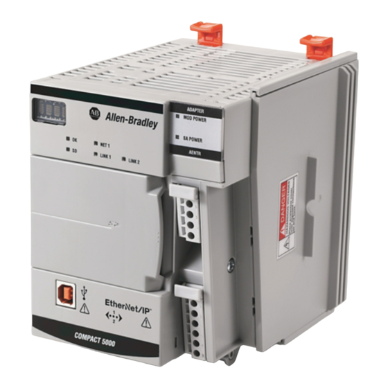
- Page 1 User Manual Original Instructions Compact 5000 EtherNet/IP Adapters 5069-AENTR, 5069-AEN2TR...
- Page 2 If this equipment is used in a manner not specified by the manufacturer, the protection provided by the equipment may be impaired. In no event will Rockwell Automation, Inc. be responsible or liable for indirect or consequential damages resulting from the use or application of this equipment.
-
Page 3: Table Of Contents
Index ............53 Rockwell Automation Publication 5069-UM007A-EN-P - February 2019... - Page 4 Table of Contents Notes: Rockwell Automation Publication 5069-UM007A-EN-P - February 2019...
-
Page 5: Preface
– Compact GuardLogix® 5380 controllers – ControlLogix® 5580 controllers – GuardLogix 5580 controllers • Use of an EtherNet/IP network • Use of various software applications from Rockwell Automation These documents contain more information concerning related products from Additional Resources Rockwell Automation. - Page 6 Preface Notes: Rockwell Automation Publication 5069-UM007A-EN-P - February 2019...
-
Page 7: Compact 5000 Ethernet/Ip Adapter Features
I/O modules. • Provides system-side power and field-side power to Compact 5000 I/O system. • Connects to multiple EtherNet/IP network topologies. • Supports as many as 31 Compact 5000 I/O modules. Rockwell Automation Publication 5069-UM007A-EN-P - February 2019... -
Page 8: Ethernet Features
EtherNet Features Adapter Communication Linear Ability to Protected Rate Network Protocol Operate as Protocol Mode a DLR Supervisor 5069-AENTR 10 Mbps Implicit 100 Mbps 1 Gbps 5069-AEN2TR 10 Mbps Supported 100 Mbps 1 Gbps Rockwell Automation Publication 5069-UM007A-EN-P - February 2019... -
Page 9: Protected Mode
• Changing Ethernet configuration settings, such as port speed. • Changing IP settings, such as IP address, mask, and DHCP mode. • Updating the device firmware. • Disabling or re-enabling external product ports. • Performing remote resets. Rockwell Automation Publication 5069-UM007A-EN-P - February 2019... -
Page 10: Perform Tasks When Not Restricted
For example, after the device is initially powered up, but no I/O connections are established yet, the device is not in Protected Mode. You can attempt to update the device firmware and the device does not reject the attempt. Rockwell Automation Publication 5069-UM007A-EN-P - February 2019... -
Page 11: Secure Digital Card
You can use third-party SD cards with the controller. You can use SD cards with as much as 32 GB of memory. Keep in mind, Rockwell Automation does not test the use of third-party SD cards with the controller. - Page 12 The adapter configuration data on the SD card is deleted before the update begins. After the firmware revision is updated, the adapter configuration is copied from the internal memory to the SD card. Rockwell Automation Publication 5069-UM007A-EN-P - February 2019...
- Page 13 Field-side power is also known as SA power. Power begins at the adapter and passes across the I/O module internal circuitry via power buses. The MOD power bus and SA power bus are isolated from each other. Rockwell Automation Publication 5069-UM007A-EN-P - February 2019...
-
Page 14: Chapter 2 Power Connectors
The 5069-AEN2TR adapter uses two RTBs to connect MOD power and SA power. You connect an external power supply to the MOD power RTB to provide MOD power. You connect an external power supply to the SA power RTB to provide SA power. Rockwell Automation Publication 5069-UM007A-EN-P - February 2019... -
Page 15: Mod Power Bus
For example, if the total MOD power current draw is 5 A, you can use a MOD power supply that is limited to 5 A. IMPORTANT You must consider current inrush requirements when you calculate the total MOD power bus current draw in the system. Rockwell Automation Publication 5069-UM007A-EN-P - February 2019... -
Page 16: Sa Power Bus
• If you use DC voltage, you must limit the SA power source to 10 A, max at 18…32V DC. • If you use AC voltage, you must limit the SA power source to 10 A, max at 18…240V AC. Rockwell Automation Publication 5069-UM007A-EN-P - February 2019... - Page 17 SA power bus. For more information on the current that the 5069 Compact I/O™ modules draw from the SA power bus, see the 5069 Compact I/O Modules Specifications Technical Data, publication 5069-TD001. Rockwell Automation Publication 5069-UM007A-EN-P - February 2019...
-
Page 18: Track Sa Power Bus Current Draw
10 mA 128 mA 128 mA 128 mA 128 mA 0 mA 0 mA 100 mA 100 mA 250 mA 250 mA Per Module System SA Power Bus Current, max = 1.222 A Rockwell Automation Publication 5069-UM007A-EN-P - February 2019... -
Page 19: Additional Sa Power Buses
For example, you can separate modules that are connected to field-side devices that require DC voltage for SA power from modules that are connected to field-side devices that require AC voltage for SA power. Rockwell Automation Publication 5069-UM007A-EN-P - February 2019... - Page 20 Chapter 2 Compact 5000 EtherNet/IP Adapter Power Requirements Figure 5 - 5069-FPD Field Potential Distributor FIELD POWER 5069-FPD SA Power Connection Rockwell Automation Publication 5069-UM007A-EN-P - February 2019...
-
Page 21: 5069-Fpd Field Potential Distributor Creates
AC type I/O modules. SA Power Bus Limited to 10 A, max SA Power Bus Limited to 10 A, max Compact 5000™ I/O DC Type I/O Modules AC Type I/O Modules Rockwell Automation Publication 5069-UM007A-EN-P - February 2019... -
Page 22: Sa Power - Additional Notes
SA power bus. The modules receive field-side power from an external power supply that is connected to the module RTB. For example, the 5069-OB16 and 5069-OB16F modules use Local Actuator (LA) terminals, that is, LA+ and LA- terminals for all module channels. Rockwell Automation Publication 5069-UM007A-EN-P - February 2019... -
Page 23: Set The Ip Address
Set the IP Address IP addresses: • The adapters ship without an IP address. • The rotary switches on the adapter are set as follows: – 5069-AENTR adapter - 999 – 5069-AEN2TR adapter - 000 Rockwell Automation Publication 5069-UM007A-EN-P - February 2019... -
Page 24: Requirements
This arc could cause an explosion in hazardous location installations. Be sure that power is removed or the area is nonhazardous before proceeding. IMPORTANT: The 5069-AENTR adapter does not have a reset button. Rockwell Automation Publication 5069-UM007A-EN-P - February 2019... -
Page 25: Other Methods To Set The Ip Address
Other Methods to Set the IP methods to change the IP address: Address • BOOTP/DHCP utility • RSLinx® Classic software • For more information on how to use these methods, see EtherNet/IP Network Device User Manual, publication ENET-UM006. Rockwell Automation Publication 5069-UM007A-EN-P - February 2019... -
Page 26: Reset The 5069-Aentr Adapter
3. Use a small tool or screwdriver to press and hold the reset button. 4. While holding in the reset button, power up the adapter. 5. Continue to hold the reset button while the 4-character display cycles through TEST, DFLT, 4, 3, 2, 1. Rockwell Automation Publication 5069-UM007A-EN-P - February 2019... - Page 27 Connect to the EtherNet/IP Network Chapter 3 6. Factory Default scrolls one time across the display. 7. Release the reset button. Reset Button Compact 5000™ I/O Rockwell Automation Publication 5069-UM007A-EN-P - February 2019...
- Page 28 Chapter 3 Connect to the EtherNet/IP Network Notes: Rockwell Automation Publication 5069-UM007A-EN-P - February 2019...
-
Page 29: Add The Module To A Project
• 5069-AENTR adapter - Version 30 or later • 5069-AEN2TR adapter - Version 28 or later 1. Verify that your project is offline. Add the Module to a Project 2. Right-click your network port, and choose New Module. Rockwell Automation Publication 5069-UM007A-EN-P - February 2019... - Page 30 In the Catalog Number field, select the adapter. For some modules, the Select Major Revision dialog box can appear. If the dialog box appears, choose the major revision of the module and click OK. c. Click Create. Rockwell Automation Publication 5069-UM007A-EN-P - February 2019...
- Page 31 4. On the New Module dialog box, complete the following tasks on the General category page: a. Type a name. b. Enter the IP address. c. In the Module Definition area, click Change. The Module Definition dialog box appears. Rockwell Automation Publication 5069-UM007A-EN-P - February 2019...
- Page 32 The specific type of the product. The Product Code maps to a catalog number. Major Revision A number that represents the functional capabilities of a device. Minor Revision A number that represents behavior changes in the device. Rockwell Automation Publication 5069-UM007A-EN-P - February 2019...
- Page 33 No direct connection from Controller (Originator) to the adapter. Status Reports device status. d. Set the Chassis Size to the number of modules including the adapter. For example, one adapter with nine I/O modules equals a chassis size of ten. Rockwell Automation Publication 5069-UM007A-EN-P - February 2019...
- Page 34 Chapter 4 Configure the Adapter e. Click OK. If you set the Connection to Status, click Yes on the Logix 5000™ dialog box. Rockwell Automation Publication 5069-UM007A-EN-P - February 2019...
- Page 35 Unicast. c. Click OK. 7. Save the project. 8. If the project does not have a communication path to the controller, click Browse to create a path. Rockwell Automation Publication 5069-UM007A-EN-P - February 2019...
- Page 36 9. On the Who Active dialog box, choose the desired path and click Set Project Path and close the dialog box. 10. Verify that the controller mode switch is in the PROG mode position 11. Click the Controller Status icon, and choose Go Online. Rockwell Automation Publication 5069-UM007A-EN-P - February 2019...
- Page 37 Configure the Adapter Chapter 4 12. On the Connected To Go Online dialog box, click Download. 13. On the Download dialog box, click Download. Rockwell Automation Publication 5069-UM007A-EN-P - February 2019...
- Page 38 Chapter 4 Configure the Adapter 14. Confirm that you want to download the project. The project downloads to the controller. The dialog box closes when the download is complete. Rockwell Automation Publication 5069-UM007A-EN-P - February 2019...
- Page 39 Put the controller mode switch in the REM position. b. Change the Logix Designer application project to Run mode. c. When prompted to Change controller mode to Remote Run, click Yes. d. Right-click the adapter, and choose Properties. Rockwell Automation Publication 5069-UM007A-EN-P - February 2019...
- Page 40 • If you connect a manually configured device to an autonegotiate device (duplex mismatch), a high rate of transmission errors can occur. Rockwell Automation Publication 5069-UM007A-EN-P - February 2019...
- Page 41 • Primary and secondary DNS Server Addresses. f. On the Module Properties dialog box, click OK. IMPORTANT If you try to change the IP address on this page, the following alert appears: g. Save the project. Rockwell Automation Publication 5069-UM007A-EN-P - February 2019...
- Page 42 Chapter 4 Configure the Adapter Notes: Rockwell Automation Publication 5069-UM007A-EN-P - February 2019...
-
Page 43: 5069-Aentr Adapter Status Indicators
EtherNet/IP communication modules have multi-character displays and status indicators to assist with performance and diagnostics. 5069-AENTR Adapter Figure 7 - 5069-AENTR Adapter Status Indicators Status Indicators Controller and EtherNet/IP Status Indicators Power Status Indicators Rockwell Automation Publication 5069-UM007A-EN-P - February 2019... - Page 44 The device has powered up and is in the Factory Default state. Use adapter as necessary. green In this case, the OK indicator is flashing red and all other indicators flash red and green. Rockwell Automation Publication 5069-UM007A-EN-P - February 2019...
- Page 45 The device has powered up and is in the Factory Default state. Use adapter as necessary. green In this case, the OK indicator is flashing red and all other indicators flash red and green. Rockwell Automation Publication 5069-UM007A-EN-P - February 2019...
-
Page 46: 5069-Aen2Tr Adapter Status Indicators
Troubleshoot the issue and remedy the cause. For example, if a Duplicate IP address condition exists, determine which devices on the network use the same IP address and change the IP addresses to unique values. Rockwell Automation Publication 5069-UM007A-EN-P - February 2019... - Page 47 There is no module power applied to the device. Apply MOD power as necessary Steady green Module power is present. None SA Power Status of SA power is unknown. Apply SA power as necessary Steady green SA power is present. None Rockwell Automation Publication 5069-UM007A-EN-P - February 2019...
- Page 48 The message shows the MAC ID of the device with the duplicate IP address. Message scrolls continuously during operation. Fault Cycle power to unit. Message appears, and scrolls continuously, during a fault. Rockwell Automation Publication 5069-UM007A-EN-P - February 2019...
-
Page 49: Compact 5000 Ethernnet/Ip Adapter Tags
• 0 = Ethernet port is not active • 1 = Ethernet port is active Port2Connected BOOL Indicates if the numbered Ethernet port is active. • 0 = Ethernet port is not active • 1 = Ethernet port is active Rockwell Automation Publication 5069-UM007A-EN-P - February 2019... - Page 50 Class 0 and Class 1 connections that are consumed by the adapter and its children. CIPTimeouts DINT A running count of the number of connections that time out, both originated and All positive values targeted, and connections to and through the adapter. Rockwell Automation Publication 5069-UM007A-EN-P - February 2019...
- Page 51 The time when the Local Clock Offset was sampled. This value is initially zero, and the — first time stamp occurs when the module synchronizes with the master clock. GrandMasterClockID SINT[8] The EUI-64 Identity of the CIP Sync Grandmaster clock the module is synced to. Rockwell Automation Publication 5069-UM007A-EN-P - February 2019...
- Page 52 Appendix B Module Tags Notes: Rockwell Automation Publication 5069-UM007A-EN-P - February 2019...
-
Page 53: Index
SD card 11 MOD power 13 mode switch 36 out-of-box state rotary switches 23 power a 5069 Compact I/O system MOD power 13 … SA power 13 track current draw 18 Protected Mode 5069-AENTR 9 Rockwell Automation Publication 5069-UM007A-EN-P - February 2019... - Page 54 Index Notes: Rockwell Automation Publication 5069-UM007A-EN-P - February 2019...
- Page 56 Rockwell Automation maintains current product environmental information on its website at http://www.rockwellautomation.com/rockwellautomation/about-us/sustainability-ethics/product-environmental-compliance.page. Allen-Bradley, Compact I/O, Compact 5000 I/O, CompactLogix, Compact GuardLogix, ControlLogix, GuardLogix, Rockwell Automation, Rockwell Software, RSLinx, RSLogix 5000, and Studio 5000 Logix Designer are trademarks of Rockwell Automation, Inc.
Need help?
Do you have a question about the Allen-Bradley Compact 5000 and is the answer not in the manual?
Questions and answers