
Related Manuals for Maico ER GH AP


Summary of Contents for Maico ER GH AP
- Page 1 Installation and operating instructions Surface-mounted exhaust air system for single-duct air ex- traction according to DIN 18017-3 ER GH AP ER GH APB www.maico-ventilatoren.com...
-
Page 2: Table Of Contents
Table of contents 8.8.1 ER-APB: Safety instruc- Table of contents tions for installation of Overview of ER GH AP/APB system ... the fire protection shut- off device......Scope of delivery ........8.8.2 Safety instructions for Intended use.......... the installation of the General safety instructions .... -
Page 3: Overview Of Er Gh Ap/Apb System
Preface stalling and using for the first time. Follow the in- structions. Pass these instructions on to the owner for safekeeping. 1 Overview of ER GH AP/APB system 1 Central screw 2 G2 air filter housing floor seal. Housing for 3 Covers 3.1 ER-A cover... -
Page 4: Scope Of Delivery
2 Scope of delivery Installation in a ventilation shaft, in the wall, front 9.2 Metal backflow 10 Exhaust socket wall or a suspended ceiling is permissible. preventer DN 75/DN 80 (provided) The fans are only intended for domestic use and similar purposes. -
Page 5: Safety Instructions Regarding In- Stallation, Operation, Cleaning And Maintenance
5 Safety instructions regarding installation, operation, cleaning and maintenance NOTICE Damage to the unit due to imbalance DANGER Danger if the relevant regula- of the impeller when conveying solid tions for electrical installations are not ob- particles. served. Never use unit to convey solid particles that could Before removing the housing cover or removing adhere to the unit. -
Page 6: System And Product Information
6 System and product information NOTICE Non-intended operation/impermiss- WARNING Risk to health if filters are not ible operation due to incorrectly mounted replaced or if there are no air filters. unit. Heavily soiled or moist air filters can accumulate Only install unit in accordance with the planning harmful substances (mould, germs, etc.). -
Page 7: Possible Combinations
• Electrical connection at rear. Cable feedthrough with stepped grommet. • Mains cable type NYM-O or NYM-J, 3 x 1.5 or 5 ER-A ER EC ER GH AP x 1.5 mm² ER-AK ER GH APB • For the wall or ceiling installation, outside the exhaust air shaft. -
Page 8: Covers: Functions
7 Technical data 6.5 Covers: Functions ER-A ER-AK ER-AH ER-AB Filter change indicator ● (6 months) with TimeStrip Filter change indicator ● ● ● (6 months) with LED Control with time module ● ● ● Control with fully automatic humidity control: Extraction ●... -
Page 9: Regulations For Operation With Fireplaces
Sufficient supply air intake must be ensured room. Ambient temperature – 10 °C to + 60 °C. during operation with air-ventilated fireplaces. Maico accepts no liability for corrosion damage The maximum permitted pressure difference per caused by improper storage, e.g. storage in a residential unit is 4 Pa. -
Page 10: Requirements In Line With Ap- Proval
8 Mounting preparations 8.1 Requirements in line with ap- 8.2 Permissible installation positions proval for AP and APB fans Wall installation, top left corner of room 8.1.1 Approval provisions Approval provision ER-APB ER-AP Number of units per Max. 3 Max. 2 fans floor, residential unit fans or 3 or 2 connec-... -
Page 11: Preparations For Er-Apb Wall Installation (With Fire Protection)
8 Mounting preparations 8.3.1 Preparations for ER-APB wall installation DANGER Danger to life due to fire trans- (with fire protection) mission in case of faulty ceiling compound. It is essential that the remaining gap between the main duct and the wall or ceiling is completely sealed with non-flammable materials that are res- istant to deformation. - Page 12 8 Mounting preparations Duct attachment with duct clamp, 12 Main duct (steel 15 Spigot folded spiral- alternatively duct attachment with clamping seams duct) band 16 Shaft wall 17 Ceiling com- pound 18 Floor ceiling 20 Steel threaded rod / stair bolt 21 Duct fastener 22 Duct clamp / clamping band...
- Page 13 8 Mounting preparations It is imperative to compensate any uneven- DANGER Danger to life due to fire trans- ness in the wall or ceiling so that the lower mission if not flush with the brickwork or with part of the housing can be installed without panel building materials.
- Page 14 8 Mounting preparations 1. Switch off mains fuse, secure against being Always note the relevant specifications for accidentally switched back on and position a electrical installations and when fitting visible warning sign. equipment. In Germany, observe DIN VDE 2. Lay power cable to the installation location. 0100 and the corresponding parts in partic- 3.
- Page 15 8 Mounting preparations 3. For fire protection systems, use ceiling com- Dowel for drill holes Main duct (steel fol- pound. To do this, encase the ceiling and pour ded spiral-seams in the material from above. duct) 4. Connect connection duct, suitable for the Connection duct: Power cable housing, to the main duct and seal for ventila-...
-
Page 16: Er-Apb: Safety Instruc
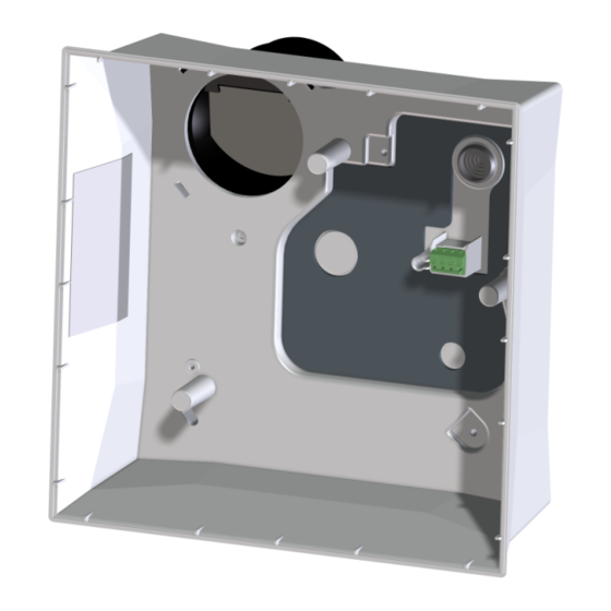
8 Mounting preparations 8.8 ER-APB shut-off device, ER-AP shutter 6 Housing Metal backflow DANGER Danger to life due to fire trans- preventer mission if the tab of the metal backflow pre- Fixing screw for 10 Exhaust socket venter is incorrectly screwed on. tab of the metal DN 75/DN 80 It is essential to fasten the metal backflow pre-... -
Page 17: Safety Instructions For The Installation Of The Plastic Shutter
8 Mounting preparations 8.9 Preparing the shutter NOTICE Unpleasant smells from the main duct. Shut-off device does not close tightly in NOTICE Odours may escape from the ventila- cases of improper installation. tion channel. Before mounting, check the correct installation If the installation position is wrong, the plastic position and check that the shut-off shutter func- shutter will not close leak-tight. -
Page 18: Housing Installation
9 Housing installation 1. Carefully remove the through-the-wall air 9.2 Mounting information blow-out adapter from the 3 locking hooks on (also Requirements in line with approval [} 10]) the sides. AP housing without fire protection device. 2. Push the supplied angled air blow-out adapter onto the fan insert until it is engaged. -
Page 19: Electrically Connecting The Unit
10 Electrical connection NOTICE Risk of damage to unit in the event of DANGER Danger from electric shock/The short-circuits. unit will be damaged if installed incorrectly Cut off and insulate PE conductor and individual with too long a power cable. cable cores that are not required! If the cable feed is too long inside the housing, the fan insert cannot be installed correctly. -
Page 20: Final Mounting
11 Final mounting Maximum length of power supply cable in the housing is 7 cm. Cut off and insulate PE conductor and individual cable cores that are not required Nominal load can be Nominal load can be Nominal load and switched without switched with permanent base load can be... -
Page 21: Key Lock
Terminal block KL ER E157.0326.0000 In case of questions, please contact: 11.3 Key lock Maico Elektroapparate-Fabrik GmbH If a key lock is desired, activate the key lock on Steinbeisstraße 20 the ER-AK, ER-AH or ER-AB cover (it is deactiv- 78056 Villingen-Schwenningen, Deutschland ated in the factory). -
Page 22: Removal
15 Removal • 100x filter change indicator (TimeStrip) ER-A cover Article no. 0084.0361 ZF EC replacement air filter for ER-AK, ER-AH • Standard model and ER-AB Article no. 0093.0758 • Air volume 30 m³/h, 60 m³/h • Installation and operating instructions for ER •... -
Page 23: Wiring Diagram
17 Wiring diagram Dispose of the packaging material in an environ- At the end of its service life, dispose of the unit in mentally-friendly way, in compliance with the reg- an environmentally-friendly way, in compliance ulations valid in the country where you are. with the regulations valid in the country where you are. - Page 24 17 Wiring diagram Motor control...
- Page 25 Notes...
- Page 28 Maico Elektroapparate-Fabrik GmbH Steinbeisstr. 20 78056 Villingen-Schwenningen Deutschland Service +49 7720 6940 info@maico.de D10.20_EN_DSW-AS-AV...
Need help?
Do you have a question about the ER GH AP and is the answer not in the manual?
Questions and answers