Table of Contents
Advertisement
Available languages
Available languages
Quick Links
Montage- und Betriebsanleitung
Installation and operating instructions
Notice de montage et mode d'emploi
Upute za montažu i uporabu
Instrukcja montażu i eksploatacji
www.maico-ventilatoren.com
Aufputz-Abluftsystem für Einrohr-Entlüftung nach DIN 18017-3
Surface-mounted exhaust air system for single-duct air extraction according to
DIN 18017-3
Système d'évacuation d'air à montage apparent pour évacuation d'air monotube
selon DIN 18017-3
Nadžbukni sustav za odsisni zrak za jednocijevni odsis zraka prema DIN 18017-3
Natynkowy system wywiewu do jednorurowego wyciągu powietrza wg DIN
18017-3
ER GH AP
ER GH APB
Advertisement
Table of Contents

Related Manuals for Maico ER GH AP


Summary of Contents for Maico ER GH AP
- Page 1 Notice de montage et mode d'emploi Upute za montažu i uporabu Instrukcja montażu i eksploatacji ER GH AP ER GH APB www.maico-ventilatoren.com Aufputz-Abluftsystem für Einrohr-Entlüftung nach DIN 18017-3 Surface-mounted exhaust air system for single-duct air extraction according to DIN 18017-3 Système d'évacuation d'air à montage apparent pour évacuation d'air monotube selon DIN 18017-3 Nadžbukni sustav za odsisni zrak za jednocijevni odsis zraka prema DIN 18017-3...
- Page 2 Vorwort Lesen Sie diese Anleitung vor der Montage und Vorwort ersten Benutzung bitte sorgfältig durch. Folgen Sie den Anweisungen. Übergeben Sie die Anlei- tungen an den Eigentümer zur Aufbewahrung.
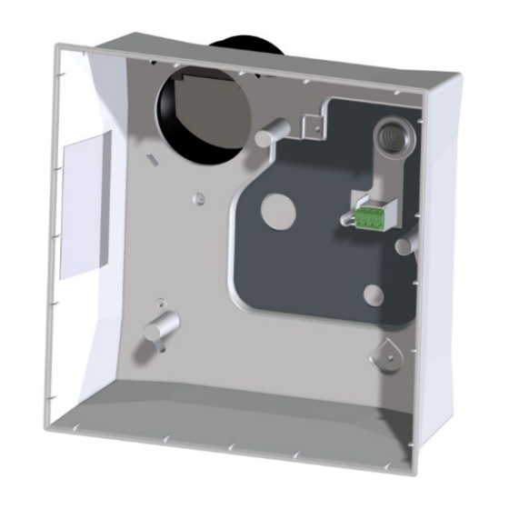
- Page 3 Systemübersicht Systemübersicht 1 Zentralschraube 3 Abdeckungen 2 G2-Luftfilter 3.1 Abdeckung ER-A...
-
Page 4: Qualifikation Fachinstallateur
4 Allgemeine Sicherheitshinweise Das Gerät darf in folgenden Situationen auf keinen Fall eingesetzt werden: 1 Lieferumfang GEFAHR Entzündungs-/Brandgefahr Aufputzgehäuse ER GH AP durch brennbare Materialien, Flüssigkeiten Artikel-Nr. 0084.0352 oder Gase in der Nähe des Geräts. • Aufputzgehäuse mit beigelegtem Kunststoff- In der Nähe des Geräts keine brennbaren Mate-... - Page 5 5 Sicherheitshinweise zu Installation, Betrieb, Reinigung und Wartung 5 Sicherheitshinweise zu Installa- WARNUNG Gesundheitsgefahr durch Chemikalien oder aggressive Gase/Dämpfe. tion, Betrieb, Reinigung und War- Chemikalien oder aggressive Gase/Dämpfe kön- tung nen die Gesundheit gefährden, insbesondere, wenn diese mit dem Gerät in die Räume verteilt GEFAHR Gefahren für Kinder und Perso- werden.
- Page 6 5 Sicherheitshinweise zu Installation, Betrieb, Reinigung und Wartung GEFAHR Gefahr bei Nichtbeachtung der WARNUNG Gesundheitsgefahr durch geltenden Vorschriften für Elektroinstallatio- mangelnden Filterwechsel oder fehlendem nen. Luftfilter. Vor dem Abnehmen der Gehäuseabdeckung Stark verschmutzte oder feuchte Luftfilter können bzw. Ausbau des Ventilatoreinsatzes und vor gesundheitsschädliche Stoffe (Schimmel, Keime Elektroinstallationen alle Versorgungsstromkreise etc.) ansammeln.
- Page 7 Insbesondere die Ausführungen von Lüftungs- kanälen und Schalldämmung beachten. Planungshinweise bzgl. Geräteposition und Ab- ständen zu anderen Fassadenkomponenten be- ER-A ER EC ER GH AP achten. ER-AK ER GH APB Eventuell Entkopplungselemente einsetzen. ER-AH ER-AB 6 System- und Produktinforma-...
- Page 8 6 System- und Produktinformationen • Ventilatoreinsatz wird mit 3 Schrauben befes- • Ausblasadapter (Lieferumfang) für Umbau Aus- tigt. blas nach hinten (Umbau Ausblasadapter für Verwendung des AP-Gehäuses [} 18]). ER EC-Ventilatoreinsatz • Ventilatoreinsatz zum Einbau in Gehäuse. Abdeckungen • Elektrische Steckverbindung für schnelle Mon- •...
- Page 9 = 10 m² Für weitere technische Daten → Typenschild. Bei Betrieb mit raumluftabhängigen Feuerstät- ten muss für ausreichende Zuluftnachströ- Für Kennlinien → www.maico-ventilatoren.com mung gesorgt werden. Die maximal zulässige Druckdifferenz pro Wohneinheit beträgt 4 Pa. Das Gerät darf in Wohneinheiten mit raumluftab- hängigen Feuerstätten nur unter folgenden Bedin-...
- Page 10 3 x 90° stemperatur – 10 °C bis + 60 °C. Leitungsbögen De- 90° ckeneinbau Für Korrosionsschäden durch unsachgemäße Lagerung übernimmt Maico keine Gewährleis- tung, z. B. bei Lagerung im feuchten Umfeld. 8 Montagevorbereitungen Drosseleinrichtung in nicht zulässig der Abluftleitung Geeignetes Befestigungsmaterial ist bausei-...
- Page 11 8 Montagevorbereitungen Wandeinbau, Raumecke rechts oben 8.3.1 Vorbereitungen für die ER-APB-Wand- montage (mit Brandschutz) Deckeneinbau Hauptleitung Anschlussleitung: (Stahlwickelfalz- Aluflexrohr AFR 80 rohr) Bundkragen Schachtwand Deckenverguss Geschossdecke Dichtmaterial, z. B. Kaltschrumpfband 1. Lüftungs-Hauptleitung innerhalb des Schach- tes fachgerecht anbringen. 2. Deckenverguss anbringen. Dazu die Decke einschalen und das Material von oben eingie- ßen.
- Page 12 8 Montagevorbereitungen 5. Für einen passenden, ebenen Unterbau sor- 6. Bundkragen aus Schachtmaterial F90 ringsum gen. um den Schacht anbringen. Alle Wand- oder Deckenunebenheiten aus- Der Bundkragen dient dem Längenaus- gleichen, damit das Gehäuse verzugsfrei an- gleich der Schachtwände im Brandfall. gebracht werden kann.
- Page 13 8 Montagevorbereitungen 2. Deckenverguss anbringen. Dazu die Decke Rohrbefestigung mit Rohrschelle, einschalen und das Material von oben eingie- alternativ Rohrbefestigung mit Lochband ßen. 3. Schachtdurchbruch für das Stahl-Wickelfalz- rohr DN 80 anbringen. 4. Rohrbefestigungen an der Decke anbringen. Nur zulässiges, geeignetes Befestigungsmate- rial verwenden.
- Page 14 8 Montagevorbereitungen 8.4 ER-AP: Vorbereitungen für den 8.5 Vorbereitungen für den elektri- Wand-, Schacht oder Deckeneinbau schen Anschluss ohne Brandschutz GEFAHR Lebensgefahr durch Strom- 1. Montagevorbereitungen wie beschrieben vor- schlag. nehmen: Vorgaben gemäß Zulassung [} 10]. Vor dem Verlegen der Netzleitung alle Versor- gungsstromkreise abschalten.
- Page 15 8 Montagevorbereitungen • Für Brandschutzsysteme muss der vorhandene ACHTUNG Gerätebeschädigung, Funktions- Restspalt zwischen Anschlussleitung und Mau- störung bei Korrosionsschäden durch Mörtel. erwerk/Plattenbaustoffen/Wand/Decke mit An das Gerät angeschlossene Lüftungsleitungen formbeständigen, nicht brennbaren Baustoffen zum Schutz vor Korrosion innerhalb des Mauer- vollständig verschlossen werden (z. B. mit Be- werks mit geeignetem Klebeband umwickeln, ton, Zementmörtel, Brandspachtelmasse).
- Page 16 8 Montagevorbereitungen 8. Netzleitung verlegen: Gerät elektrisch anschlie- ßen [} 20]. 8.8 ER-APB-Absperrvorrichtung, ER-AP-Verschlussklappe 6 Gehäuse Metall-Rück- 8.8.1 ER-APB: Sicherheitshinweise zur Monta- schlagklappe ge der Brandschutz-Absperrvorrichtung Unbedingt die zulässigen Einbaupositionen be- Befestigungs- 10 Ausblasstutzen schraube für La- DN 75/DN 80 achten: Zulässige Einbaulagen für AP- und APB- sche der Metall- Ventilatoren [} 10].
- Page 17 8 Montagevorbereitungen 6. Zulässige Anschlussleitung an der Hauptlei- GEFAHR Bei ER-APB-Anschluss außer- tung anschließen und lüftungstechnisch ab- halb des Schachts: Lebensgefahr durch dichten, zum Beispiel mit einem Kaltschrumpf- Brand-übertragung bei falscher Verbindung band. des Metall-Ausblasstutzens mit der An- 7. Mauer-/Plattenbaustoff-Verschluss anbringen. schlussleitung.
- Page 18 9 Gehäusemontage 8.10 Blindstopfen anbringen 1. Den mitgelieferten Blindstopfen an den Venti- latoreinsatz anbringen. 8.11 Umbau Ausblasadapter für Ver- wendung des AP-Gehäuses ACHTUNG Bei falschem Einbau des Aus- blasadapters ist die Funktion des Geräts be- einträchtigt. Sicherstellen, dass der Adapter dicht am Gehäu- se anliegt.
-
Page 19: Elektrischer Anschluss
10 Elektrischer Anschluss Das Gehäuse muss verzugsfrei eingesetzt werden. Ist dies nicht der Fall, kann der Ventila- toreinsatz nicht richtig in das Gehäuse einrasten und die auf dem Typenschild angegebene Schutzart ist nicht mehr gewährleistet. 10 Elektrischer Anschluss 6 Gehäuse 7 Klemmleiste ACHTUNG Gerätebeschädigung durch fehler- haften Anschluss. -
Page 20: Gerät Elektrisch Anschließen
11 Endmontage • bei bestimmungsgemäßem Einbau. • bei korrekt im Aufputzgehäuse eingerastetem Ventilatoreinsatz. • bei ordnungsgemäßer Einführung der Netzlei- tung durch den Stufennippel. • bei verschraubter, geschlossener und einge- rasteter Abdeckung. 10.1 Gerät elektrisch anschließen 1. Vor Zugang zu den Anschlussklemmen alle 4. -
Page 21: Gerät Bedienen
12 Gerät bedienen 2. Luftfilter einlegen und das Abdeckungsoberteil herunterklappen (Oberteil muss hörbar einras- ten). 3. Funktionstest durchführen: Alle Gerätefunktio- nen testen (Nachlauf, Intervall, Feuchtesteue- rung etc.). 2. Mit den 3 beiliegenden Schrauben (4x10) be- festigen. Schrauben nicht überdrehen. 3. Festen Sitz des Ventilatoreinsatzes prüfen. 11.3 Tastensperre Falls Tastensperre gewünscht, an der Abdeckung ER-AK, ER-AH oder ER-AB die Tastensperre ak-... - Page 22 Artikel-Nr. 0084.0362 E-Mail: ersatzteilservice@maico.de • Komfortausführung mit intelligentem Zeitmodul • Fördervolumen 30 m³/h / 60 m³/h gemäß Werk- Ersatzteile können unter www.shop.maico- seinstellung. Weitere einstellbare Volumenströ- me: Grundlast 20 m³/h, 30 m³/h, 40 m³/h, 60 m³/ ventilatoren.com bestellt werden. h oder 100 m³/h, Volllast 20 m³/h, 30 m³/h, 40 m³/h, 60 m³/h oder 100 m³/h...
-
Page 23: Umweltgerechte Entsorgung
15 Demontage • Fördervolumen 30 m³/h / 60 m³/h gemäß Werk- 1. Vor Zugang zu den Anschlussklemmen alle seinstellung. Weitere einstellbare Volumenströ- Versorgungsstromkreise abschalten (Netzsi- me: Grundlast 20 m³/h, 30 m³/h, 40 m³/h, 60 m³/ cherung ausschalten), gegen Wiedereinschal- h, 100 m³/h, Volllast 20 m³/h, 30 m³/h, 40 m³/h, ten sichern und ein Warnschild sichtbar an- 60 m³/h, 100 m³/h bringen. - Page 24 Preface Please read the instructions carefully before in- Preface stalling and using for the first time. Follow the in- structions. Pass these instructions on to the owner for safekeeping.
-
Page 25: System Overview
System overview System overview 1 Central screw 3 Covers 2 G2 air filter 3.1 ER-A cover... -
Page 26: Scope Of Delivery
1 Scope of delivery vicinity of the unit. Do not place any flammable materials, liquids or ER GH AP surface-mounted housing gases near the unit, which may ignite in the event Article no. 0084.0352 of heat or sparks and catch fire. - Page 27 5 Safety instructions regarding installation, operation, cleaning and maintenance NOTICE Damage to unit due to steam-satur- DANGER Danger of electric shock from ated or greasy air or adhering solid particles. operating the unit when not fully mounted. Steam-saturated or greasy air or solid particles Electric components are a potential source of which may adhere to the unit, can soil the unit electric shock.
-
Page 28: Installation Conditions
6 System and product information DANGER Danger due to fire transmission WARNING Risk of injury and health risk if an incorrect connection duct is connected to the in the event of changes or modifications or if housing. Always use the correct cable material components which are not permitted are used. -
Page 29: Possible Combinations
• Permissible air outlet direction for wall installa- tion towards the rear. • Fan insert is fastened with 3 screws. ER-A ER EC ER GH AP ER EC fan insert ER-AK ER GH APB • Fan insert for installation in housing. -
Page 30: Regulations For Operation With Fireplaces
• A room from which the air is to be extracted conditions: must be fitted with a non-closable, free supply • the evaluation criteria drawn up by the respons- air cross section of at least 150 cm², e.g. with ible, regional master chimney sweep are met; Maico MLK door ventilation grille. -
Page 31: Technical Data Table
90° Only store unit horizontally in a suitable, dry ceiling installation room. Ambient temperature – 10 °C to + 60 °C. Maico accepts no liability for corrosion damage caused by improper storage, e.g. storage in a damp environment. Regulating equip-... - Page 32 8 Mounting preparations Approval provision ER-APB ER-AP 8.3 ER-APB: Preparations for installa- Wall/ceiling opening Brickwork or concrete: tion with fire protection require- for DN 80 unit con- 130 mm. ments nection duct Board materials (F90): NOTICE Damage to unit, malfunctioning in the Outer Ø...
- Page 33 8 Mounting preparations 4. Cut flexible aluminium duct to length, observe Compensate any unevenness in the wall or a maximum duct length of 2 m. ceiling so that the housing can be installed Dimension the length of the flexible alu- without warping. Otherwise it may be that minium duct so that it protrudes from the the fan insert can no longer be inserted into wall or shaft so that the ER connection...
- Page 34 8 Mounting preparations 2. Apply ceiling compound. To do this, encase Duct attachment with duct clamp, the ceiling and pour in the material from alternatively duct attachment with clamping above. band 3. Make shaft opening for the DN 80 steel folded spiral-seams duct.
- Page 35 8 Mounting preparations 8.4 ER-AP: Preparations for wall, 8.5 Preparations for the electrical shaft or ceiling installation without connection fire protection DANGER Danger to life from electric 1. Carry out installation preparations as de- shock. scribed: Requirements in line with approval Before laying the power cable, switch off all sup- ply circuits.
- Page 36 8 Mounting preparations • For fire protection systems, the gap remaining NOTICE Damage to unit, malfunctioning in the between the connection duct and brickwork/wall event of corrosion damage from mortar. boards/wall/ceiling must be fully sealed with Wrap ventilation ducts, connected to the unit, non-flammable materials that are resistant to with a suitable adhesive tape to protect against deformation (e.g.
- Page 37 8 Mounting preparations 8. Lay power cable: Electrically connecting the unit [} 41]. 8.8 ER-APB shut-off device, ER-AP shutter 6 Housing Metal backflow 8.8.1 ER-APB: Safety instructions for installa- preventer tion of the fire protection shut-off device It is essential to observe the permissible installa- Fixing screw for 10 Exhaust socket tab of the metal...
- Page 38 8 Mounting preparations 7. Apply wall/board compound. Seal gap DANGER For ER-APB connection outside between brickwork and folded spiral-seams the shaft: Danger to life due to fire transmis- duct. The gap remaining must be fully sealed sion if the metal exhaust socket is incorrectly with non-flammable materials that are resist- connected to the connection duct.
-
Page 39: Mounting Information
9 Housing installation 8.11 Conversion of air blow-out ad- apter for using the AP housing NOTICE In case of incorrect installation of the air blow-out adapter, the function of the unit is impaired. Make sure that the adapter is tightly fitted to the housing. -
Page 40: Electrical Connection
10 Electrical connection The housing must be inserted without any dis- tortion. Failure to do so will mean that the fan in- sert cannot engage correctly in the housing and the degree of protection stated on the rating plate is no longer ensured. 10 Electrical connection 6 Housing 7 Terminal block... -
Page 41: Final Mounting
11 Final mounting • if the power cable is properly inserted through • with the cover screwed, closed and locked in the stepped grommet; place. • with the fan insert correctly engaged in the surface-mounted housing; 10.1 Electrically connecting the unit 1. -
Page 42: Operating The Unit
12 Operating the unit 2. Insert the air filter and fold down the upper part of the cover (upper part must audibly en- gage). 3. Run function test: Test all unit functions (over- run time, interval, humidity control etc.). 2. Fasten with the 3 supplied screws (4x10). Do not over-tighten screws. -
Page 43: Spare Parts
40 m³/h, 60 m³/h, 100 m³/h Terminal block KL ER E157.0326.0000 • Installation and operating instructions for ER In case of questions, please contact: EC-Abdeckungen Maico Elektroapparate-Fabrik GmbH ER-AK cover Steinbeisstraße 20 Article no. 0084.0362 78056 Villingen-Schwenningen, Deutschland • Comfort version with intelligent time module Tel. -
Page 44: Air Filter
15 Removal 1. Before accessing the connection terminals, Air filter shut down all supply circuits (switch off mains ZF EC+ replacement air filter for ER-A fuse), secure against being accidentally switched back on and position a visible warn- Article no. 0093.0610 ing sign. -
Page 45: Avant-Propos
Avant-propos Veuillez lire attentivement cette notice avant le Avant-propos montage et la première utilisation. Suivez les ins- tructions. Remettez les notices au propriétaire pour conservation. -
Page 46: Vue D'ensemble Du Système
Vue d'ensemble du système Vue d'ensemble du système 1 Vis centrale 3 Caches de protection 2 Filtre à air G2 3.1 Cache de protection ER-A... -
Page 47: Volume De Fourniture
4 Consignes de sécurité générales 1 Volume de fourniture Ne jamais utiliser l'appareil dans les situations Boîtier apparent ER GH AP suivantes : N° de réf. 0084.0352 • Boîtier apparent avec raccord de soufflage en DANGER Risque d'inflammation / d'incen- plastique pour le raccordement avec la gaine die résultant de la présence de matériaux, li-... - Page 48 5 Consignes de sécurité pour l'installation, le fonctionnement, le nettoyage et l'entretien ATTENTION Endommagement de l'appareil DANGER Risque d'explosion dû aux sub- pendant la phase de construction par encras- stances explosives se trouvant dans les sys- sement de l'appareil et des gaines d'aération. tèmes d'aspiration de laboratoire.
- Page 49 5 Consignes de sécurité pour l'installation, le fonctionnement, le nettoyage et l'entretien DANGER Danger en cas de non-respect AVERTISSEMENT Danger pour la santé des consignes en vigueur relatives aux instal- suite à des remplacements de filtres trop lations électriques. rares ou à l'absence de filtres à air. Avant de retirer le cache du boîtier ou le démon- Des filtres à...
-
Page 50: Conditions De Montage
6 Informations sur le système et le produit • avec une distance suffisante par rapport au mur AVERTISSEMENT Risque de blessure et et au plafond. pour la santé en cas de modifications ou de • si l'appareil est entièrement assemblé. transformations ou encore en cas d'utilisation •... - Page 51 6 Informations sur le système et le produit • Soufflage vers l'arrière, le haut ou sur le côté, à Insert de ventilateur ER EC droite par rotation du boîtier de 90°. • Insert de ventilateur pour montage dans le boî- • ER-AP : Version sans protection contre les in- tier.
-
Page 52: Directives Relatives À Une Utilisa- Tion Avec Un Foyer
7 Caractéristiques techniques ER-A ER-AK ER-AH ER-AB Marche / Arrêt du niveau charge pleine par interrupteur ● ● ● ● d'éclairage ou interrupteur séparé. En cas de commande manuelle (p. ex. interrupteur d'éclairage) s'appliquent la temporisation de démarrage et la durée de fonctionne- ment par temporisation. -
Page 53: Préparatifs De Montage
Température ambiante de – 10 °C à + 60 °C. Pour des dommages de corrosion dus à un sto- ckage non conforme, Maico déclinera tout re- cours en garantie, p. ex. en cas de stockage dans Dispositif d'étrangle- Non admissible un environnement humide. - Page 54 8 Préparatifs de montage Montage au plafond Clause d'agrément ER-APB ER-AP Matériaux de plaques (F90) : diamètre extérieur du tube 8.2 Positions d'installation autorisées pour ventilateurs AP et APB Montage mural, angle de la pièce en haut à gauche 8.3 ER-APB : Préparatifs pour le mon- tage avec contraintes techniques de protection contre les incendies ATTENTION Endommagement de l'appareil,...
- Page 55 8 Préparatifs de montage 1. Poser la gaine principale de ventilation à l'inté- Mesurer la longueur de gaine flexible alu de rieur de la gaine dans les règles de l'art. manière à ce que celle-ci dépasse le mur ou 2. Effectuer un scellement dans le plafond. Pour la gaine pour pouvoir monter ultérieure- ce faire, réaliser un coffrage du plafond et cou- ment la pièce de raccordement ER.
- Page 56 8 Préparatifs de montage 21 Fixation de gaine 22 Collier de ser- DANGER Danger de mort à cause de la ronde rage / Ruban per- propagation d'incendie, en présence d'un foré scellement défectueux dans le plafond. 23 Tuyau agrafé en 24 Scellement ma- Obturer parfaitement l'interstice résiduel entre la acier...
- Page 57 8 Préparatifs de montage 8. Réaliser un passage DN 80 pour la pièce de 2. Gaines autorisées pour le raccordement sans raccordement d'appareil dans le faux plafond contraintes en matière de protection contre les (aucune résistance au feu n'est prescrite). Te- incendies : nir compte impérativement des positions de •...
- Page 58 8 Préparatifs de montage 8.6 Préparatifs montage mural obturé avec des matériaux indéformables et Chevilles pour non inflammables (p. ex. béton, mortier, mastic trous de perçage réfractaire). Consignes de montage ATTENTION Endommagement de l'appareil, • Utiliser impérativement les matériels appropriés dysfonctionnement en cas de corrosion pro- au boîtier AP.
- Page 59 8 Préparatifs de montage 4. Connecter la gaine de raccordement adaptée Chevilles pour Gaine principale au boîtier à la gaine principale et assurer trous de perçage (tuyau agrafé en l'étanchéité de la ventilation. acier) 5. Mettre la gaine de raccordement à longueur, Gaine de raccorde- Câble secteur tenir compte de la longueur maximale de...
- Page 60 8 Préparatifs de montage 8.8 Dispositif d'arrêt ER-APB, volet de fermeture ER-AP 6 Boîtier Clapet anti-retour 8.8.1 ER-APB : Consignes de sécurité pour le métallique montage du dispositif d'arrêt anti-incendie Vis de fixation 10 Raccord de souf- Tenir compte impérativement des positions de pour languette du flage DN 75 / montage admissibles : Positions d'installation au-...
- Page 61 8 Préparatifs de montage 6. Connecter la gaine de raccordement admis- DANGER En cas de raccordement ER- sible à la gaine principale et assurer l'étan- APB hors de la gaine : Danger de mort à chéité de ventilation, par exemple avec du ru- cause de la propagation d'incendie, en cas ban rétractable à...
-
Page 62: Montage Du Boîtier
9 Montage du boîtier 8.10 Montage du bouchon borgne 1. Monter l'insert de ventilateur avec les bou- chons borgnes fournis. 8.11 Transformation d'adaptateur de soufflage pour l'utilisation du boîtier ATTENTION En cas de montage erroné de l'adaptateur de soufflage, le fonctionnement de l'appareil est perturbé. -
Page 63: Branchement Électrique
10 Branchement électrique Le volet de fermeture en plastique doit être Le boîtier doit être positionné sans déforma- préparé en conséquence pour pouvoir assurer tion. Dans le cas contraire, l'insert de ventilateur ne peut pas s'encliqueter correctement dans le l'étanchéité dans la position de montage : Pré- boîtier et le type de protection indiqué... -
Page 64: Montage Final
11 Montage final • le montage est conforme aux prescriptions. • l'insert de ventilateur s'enclenche correcte- ment dans le boîtier apparent. • l'introduction du câble secteur dans le raccord cannelé est correcte. • le cache de protection est vissé, fermé et en- cliqueté. -
Page 65: Verrouillage Des Touches
12 Utilisation de l'appareil 2. Placer le filtre à air et rabattre la partie supé- rieure du cache de protection (la partie supé- rieure doit s'encliqueter de manière audible). 3. Effectuer un test de fonctionnement : Tester toutes les fonctions d'appareil (temporisation, intervalle, commande en fonction de l'humidité... -
Page 66: Pièces De Rechange
N° de réf. 0084.0363 Adressez vos questions à : • Version avec commande en fonction de l'humi- dité et module intelligent de temporisation Maico Elektroapparate-Fabrik GmbH Steinbeisstraße 20 • Débits d'air de 30 m³/h / 60 m³/h selon réglage 78056 Villingen-Schwenningen, Allemagne usine. Autres débits d'air réglables : charge de Tél. -
Page 67: Filtre À Air
15 Démontage • Débits d'air de 30 m³/h / 60 m³/h selon réglage Filtre à air permanent de rechange ZF ECD usine. Autres débits d'air réglables : charge de pour ER-AK, ER-AH et ER-AB base 20 m³/h, 30 m³/h, 40 m³/h, 60 m³/h ou Réf. 0093.1561 100 m³/h, charge pleine 20 m³/h, 30 m³/h, 40 •... - Page 68 16 Élimination dans le respect de l'environnement une élimination et un recyclage res- pectueux de l'environnement (→ lé- gislation concernant la gestion des déchets). 1. Triez les composants selon les groupes de matériaux. 2. Éliminez les matériaux d'emballage (carton, matériaux de remplissage, plastiques) via des systèmes de recyclage et des déchetteries adaptés.
- Page 69 Uvodna riječ Pozorno pročitajte ove upute prije montaže i prve Uvodna riječ uporabe. Slijedite upute. Predajte upute vlasniku u svrhu čuvanja.
-
Page 70: Pregled Sustava
Pregled sustava Pregled sustava 1 Središnji vijak 3 Poklopci 2 G2 zračni filtar 3.1 Poklopac ER-A... -
Page 71: Opseg Isporuke
1 Opseg isporuke U blizini uređaja ne odlažite zapaljive materijale, tekućine ili plinove koji se mogu zapaliti zbog Nadžbukno kućište ER GH AP topline ili stvaranja iskri i izazvati požar. Br. artikla 0084.0352 OPASNOST Opasnost od eksplozije zbog •... - Page 72 5 Sigurnosne upute u svezi s instalacijom, načinom rada, čišćenjem i održavanjem PAŽNJA Oštećenje uređaja zbog zraka koji je OPASNOST Opasnost od strujnog udara zasićen vodenom parom ili sadrži masnoće ili pri radu s nepotpuno ugrađenim uređajem. zalijepljenih čestzica čvrste tvari. Na električnim komponentama postoji opasnost Zrak koji je zasićen voden parom ili sadrži od strujnog udara.
- Page 73 6 Informacije o sustavu i proizvodu OPASNOST Opasnost zbog prijenosa UPOZORENJE Opasnost od ozljede i požara. opasnost za zdravlje pri izmjenama ili ako je na kućište priključen pogrešan priključni pregradnjama ili pri primjeni nedopuštenih vod. Svakako upotrijebite materijale za vodove komponenti.
- Page 74 • Za zidnu i stropnu montažu unutar, izvan ventilacijskog okna. • Dopušteni smjer ispuhivanja kod zidne montaže. ER-A ER EC ER GH AP • Element ventilatora pričvršćuje se sa 3 zavrtnja. ER-AK ER GH APB Element ventilatora ER EC ER-AH •...
- Page 75 7 Tehnički podaci ER-A ER-AK ER-AH ER-AB Regulacija s dojavnikom pokreta. Stupanj punog ● opterećenja nakon prepoznatog pokreta (doseg osjetnika pokreta 5 m) Proizvod bez barijere zbog automatskog uključivanja i ● ● isključivanja Bez mogućnosti upravljanja brzinom ● ● ● ● Električni utični spoj za brzo spajanje ER EC s kućištem ●...
- Page 76 Uređaj se u stambenim jedinicama s U slučaju oštećenja uzrokovanih hrđanjem zbog kotlovnicama koje ovise o zraku u prostoru smiju nestručnog skladištenja Maico ne preuzima ugraditi samo pod sljedećim uvjetima: odgovornost, npr. pri skladištenju u vlažnom • Ispunjeni su kriteriji ocjenjivanja u odgovoru s okruženju.
- Page 77 8 Pripreme za montažu Zidna ugradnja, kut prostorije gore desno Propis za ER-APB ER-AP odobrenje maks. maks. duljina duljina 2 m 2 m (→ (→ odobrenje). odobrenje). Lukovi vodova u maks. 90° savijeni, priključnom vodu uspinjući uređaja Dopušteni broj maks. 1 x maks.
- Page 78 8 Pripreme za montažu 8.3.1 Pripreme za zidnu montažu ER-APB (sa OPASNOST Opasnost po život zbog protupožarnom zaštitom) prijenosa požara kada je stropni lijev neispravan. Preostali procjep između glavnog voda i zida ili stropa obvezno potpuno zatvoriti s nezapaljivim materijalima stabilnog oblika. Za to koristite primjerice beton ili cementnim mortom.
- Page 79 8 Pripreme za montažu Cijevni pričvrsni element sa cijevnom 12 Glavni vod 15 Spoj (čelična spiralna obujmicom, šavna cijev) kao drugo rješenje cijevni pričvrsni element s 16 Stijenka okna 17 Stropni lijev vrpcom s rupama 18 Strop etaže 20 Čelična navojna šipka/viseći vijak 21 Cijevni pričvrsni 22 Cijevna obujmica/...
- Page 80 8 Pripreme za montažu Svakako ujednačite sve neravnine na zidu ili OPASNOST Opasnost po život zbog stropu, kako bi se donji dio kućišta mogao prijenosa požara kada je stropni lijev postaviti bez propuha. U protivnom može neispravan. Preostali procjep između glavnog voda i zida ili doći do toga da se element ventilatora više stropa obvezno potpuno zatvoriti s nezapaljivim ne može umetnuti u donji dio kućišta ili...
- Page 81 8 Pripreme za montažu 1. Isključite mrežni osigurač, zaštitite ga od Pri postavljanju električne instalacije i pri ponovnog uključivanja i postavite vidljivu montaži uređaja svakako se pridržavajte pločicu s upozorenjem. trenutačnih propisa, a u Njemačkoj 2. Postavite mrežni vod na mjesto montaže. posebno norme DIN VDE 0100 s 3.
- Page 82 8 Pripreme za montažu 3. Za protupožarne sustave postavite stropni Tiple za otvore Glavni vod (čelični lijev. U tu svrhu ogulite strop i ulijte materijal obloženi odozgo. spirokanal) 4. Priključite odgovarajući priključni vod za Priključni vod: Mrežni vod kućište na glavni vod i zabrtvite ga Čelični obloženi ventilacijski-tehnički.
- Page 83 8 Pripreme za montažu 8.8 Uređaj za isključivanje ER-APB, žaluzina ER-AP 6 Kućište Metalni štitnik od 8.8.1 ER-APB: Sigurnosne upute za montažu povratnog toka protupožarnog uređaja za isključivanje Vijak za 10 Odsisno postolje Svakako vodite računa o dopuštenim položajima pričvršćivanje za DN 75/DN 80 ugradnje: Dopušteni položaji ugradnje za AP i vezicu metalne...
- Page 84 8 Pripreme za montažu 6. Priključite dopušteni priključni vod na glavni OPASNOST Kod priključka ER-APB izvan vod i zabrtvite ga ventilacijski-tehnički, npr. okna: Opasnost po život zbog prijenosa hladnom skupljajućom vrpcom. požara kod pogrešnog vijčanog spoja 7. Postavite zatvarač zida/materijala ploče. metalnog odsisnog postolja s priključnim Zatvorite procjep između zidne konstrukcije i vodom.
- Page 85 9 Montaža kućišta 8.11 Nadogradnja adaptera za ispuhivanje za uporabu AP kućišta PAŽNJA Ako se adapter za ispuhivanje pogrešno ugradi, funkcija uređaja je narušena. Osigurajte da adapter hermetično naliježe na kućište. 1. Oprezno odspojiti prolazni adapter za ispuhivanje sa 3 pričvrsne kuke na bočnim stranama.
-
Page 86: Električni Priključak
10 Električni priključak Kućište ne smije imati propuh kada se umetne. Ako to nije slučaj, element ventilatora ne može ispravno sjesti u kućište i više nije zajamčena vrsta zaštite navedena na tipskoj pločici. 10 Električni priključak 6 Kućište 7 Stezna letvica PAŽNJA Oštećenje uređaja zbog pogrešnog priključivanja. - Page 87 11 Završna montaža • u slučaju namjenske ugradnje. • u slučaju elementa ventilatora koji je ispravno dosjeo u nadžbukno kućište. • u slučaju propisnog uvođenja mrežnog voda kroz stupnjeviti naglavak. • u slučaju vijcima spojenog, zatvorenog ili dosjelog poklopca. 10.1 Električno priključivanje uređaja 1.
-
Page 88: Rukovanje Uređajem
12 Rukovanje uređajem 2. Umetnite zračni filtar i sklopite gornji dio poklopca prema dolje (gornji dio mora sjesti tako da se čuje). 3. Obavite ispitivanje rada: Ispitajte sve funkcije uređaja (naknadni rad, interval, regulacija vlažnosti, itd.). 2. Pričvrstiti s 3 priložena vijka (4x10). Nemojte previše okrenuti vijke. -
Page 89: Rezervni Dijelovi
20 m³/h, 30 m³/h, 40 m³/h, nazivno opterećenje Stezna letvica KL ER E157.0326.0000 40 m³/h, 60 m³/h, 100 m³/h U slučaju pitanja • Upute za montažu i uporabu ER EC- Maico Elektroapparate-Fabrik GmbH Abdeckungen Steinbeisstraße 20 Poklopac ER-AK 78056 Villingen-Schwenningen, Njemačka Br. artikla 0084.0362 Tel. +49 7720 694 445 •... - Page 90 15 Demontaža • Volumen zraka 30 m³/h / 60 m³/h u skladu s 15 Demontaža tvorničkom postavkom. Dodatni volumeni zraka Demontažu smije obaviti samo ovlašteni koji se mogu namjestiti: Osnovno opterećenje 20 m³/h, 30 m³/h, 40 m³/h, 60 m³/h, 100 m³/h, električar: Kvalifikacije stručnog instalatera [} 71]. puno opterećenje 20 m³/h, 30 m³/h, 40 m³/h, 1.
- Page 91 Przedmowa Przed rozpoczęciem prac montażowych i przed Przedmowa pierwszym użyciem należy starannie przeczytać niniejszą instrukcję. Postępować zgodnie z zale- ceniami. Przekazać te instrukcje właścicielowi na przechowanie.
-
Page 92: Przegląd Systemu
Przegląd systemu Przegląd systemu 1 Śruba centralna 3 Osłony 2 Filtr powietrza G2 3.1 Osłona ER-A... -
Page 93: Zakres Dostawy
(z oknami zewnętrznymi) znajdujących się np. w wielopiętrowych budynkach mieszkalnych, do- 1 Zakres dostawy mach seniora lub kompleksach hotelowych. Obudowa natynkowa ER GH AP Ponadto można je montować w szybie wentyla- Nr artykułu 0084.0352 cyjnym, ścianie, ścianie przedniej lub suficie pod- wieszanym. - Page 94 5 Wskazówki dotyczące bezpieczeństwa zainstalowania, eksploatacji, czyszczenia i konser- wacji UWAGA Niebezpieczeństwo uszkodzenia NIEBEZPIECZEŃSTWO Obecność gazów urządzenia w przypadku długotrwałego tło- i/lub pyłów powoduje zagrożenie wybuchem. czenia powietrza nasyconego parą wodną. Może dojść do zapłonu potencjalnie wybucho- Używanie urządzenia do tłoczenia powietrza na- wych gazów i pyłów, a tym samym silnych wybu- syconego parą...
- Page 95 5 Wskazówki dotyczące bezpieczeństwa zainstalowania, eksploatacji, czyszczenia i konser- wacji NIEBEZPIECZEŃSTWO Istnieje niebezpie- NIEBEZPIECZEŃSTWO Niebezpieczeń- czeństwo porażenia prądem elektrycznym stwo w przypadku nieprzestrzegania aktualnie podczas eksploatacji niekompletnie zamonto- obowiązujących przepisów dotyczących in- wanego urządzenia. stalacji elektrycznych. Istnieje niebezpieczeństwo porażenia prądem Przed przystąpieniem do zdjęcia osłony obudo- elektrycznym przez komponenty elektryczne.
- Page 96 5 Wskazówki dotyczące bezpieczeństwa zainstalowania, eksploatacji, czyszczenia i konser- wacji NIEBEZPIECZEŃSTWO Istnieje niebezpie- OSTRZEŻENIE Wykonywanie później- czeństwo przeniesienia się pożaru. szych przeróbek lub montażu elementów do- w przypadku podłączenia do obudowy niewłaści- datkowych niesie ze sobą niebezpieczeństwo wego przewodu zasilającego. Należy koniecznie zranienia lub uszczerbku na zdrowiu.
-
Page 97: Warunki Montażu
6 Informacje o systemie i produk- 6.1 Świadectwa dopuszczenia Świadectwa dopuszczenia dostępne są na zapy- tanie. 6.2 Warunki montażu ER-A ER EC ER GH AP W przypadku instalacji wg DIN 18017-3 zasto- ER-AK ER GH APB sowanie dopuszczalne jest wyłącznie: ER-AH • w jednostkowych instalacjach wyciągowych ze wspólnym kanałem głównym. - Page 98 6 Informacje o systemie i produkcie Wkład wentylatora ER EC Osłony • Wkład wentylatora do montażu w obudowie. • Osłona z filtrem powietrza wywiewanego. Łatwa wymiana filtra bez użycia narzędzi. • Elektryczne złącze wtykowe do szybkiego mon- tażu w obudowie. • ER-AH i ER-AB: produkty bez barier, które włą- czają...
- Page 99 7 Dane techniczne ER-A ER-AK ER-AH ER-AB Praca z pełną wydajnością (60 m³/h); ustawienia opóź- ● ● ●** nienia włączenia 0, 30, 60*, 90 lub 120 s Ustawienia czasu wybiegu na stopniu pełnej wydajności ● ● ● 0, 3, 6, 15*, 24 lub 30 min Możliwość...
- Page 100 Dopuszczalna liczba maks. 1 x maks. 2 x 90° +60°C. kolanek kanału przy 90° Firma Maico nie ponosi odpowiedzialności z tytu- montażu ściennym łu gwarancji w przypadku szkód wywołanych przez korozję na skutek nieprawidłowego składo- wania, np. w wilgotnym otoczeniu. 8 Przygotowania do montażu Dopuszczalna liczba maks.
- Page 101 8 Przygotowania do montażu 8.2 Dopuszczalne położenia monta- 8.3 ER-APB: Przygotowania do mon- żowe wentylatorów APB i AP tażu z wymaganiami ochrony prze- ciwpożarowej Montaż ścienny, narożnik pomieszczenia po le- wej na górze UWAGA Szkody powodowane przez korozję wywołaną przez zaprawę są przyczyną uszko- dzenia bądź...
- Page 102 8 Przygotowania do montażu 5. Zadbać o dopasowaną, płaską podbudowę. NIEBEZPIECZEŃSTWO Przeniesienie się Wyrównać wszelkie nierówności ściany lub pożaru na skutek zastosowania wadliwej za- prawy stropowej grozi śmiercią. sufitu, aby zapobiec odkształceniu obudo- Koniecznie całkowicie zamknąć szczelinę pozo- wy podczas jej zakładania. W przeciwnym stałą...
- Page 103 8 Przygotowania do montażu 23 Stalowy przewód 24 Zamknięcie mu- NIEBEZPIECZEŃSTWO Przeniesienie się ze szwem spiral- ru / płytowego pożaru na skutek zastosowania wadliwej za- materiału budow- prawy stropowej grozi śmiercią. lanego Koniecznie całkowicie zamknąć szczelinę pozo- 25 Sufit podwieszo- 26 Śruby stalowe lub stałą...
- Page 104 8 Przygotowania do montażu 7. Przymocować kolano za pomocą 3 śrub stalo- 2. Przewody przyłączeniowe dopuszczonego ty- wych lub 3 stalowych nitów jednostronnych. pu, podłączane bez uwzględnienia wymagań ochrony przeciwpożarowej: 8. Umieścić w suficie podwieszanym przepust • Montaż w szybie/ścienny: Aluminiowy przewód DN 80 do króćców przyłączeniowych urządzeń giętki o średnicy przyłącza DN 80, długość...
- Page 105 8 Przygotowania do montażu 8.6 Przygotowania montażu ściennego nych wymiarowo, niepalnych materiałów bu- Kołki do otworów dowlanych (np. betonu, zaprawy cementowej, wierconych ognioodpornej masy szpachlowej). Wskazówki montażowe UWAGA Szkody powodowane przez korozję • Należy koniecznie używać materiałów przewo- wywołaną przez zaprawę są przyczyną uszko- dów dostosowanych do obudowy AP.
- Page 106 8 Przygotowania do montażu 3. Nałożyć zaprawę stropową dla systemów Kołki do otworów Kanał główny (sta- ochrony przeciwpożarowej. W tym celu ode- wierconych lowy przewód ze skować sufit i wlać materiał od góry. szwem spiralnym) 4. Podłączyć do kanału głównego przewód zasi- Przewód przyłącze- Przewód sieciowy lający dostosowany do obudowy, po czym...
- Page 107 8 Przygotowania do montażu 8.8 Klapa odcinająca ER-APB, żaluzja ER-AP 6 Obudowa Metalowa klapa 8.8.1 ER-APB: Wskazówki dotyczące bezpie- zwrotna czeństwa montażu przeciwpożarowej klapy odcinającej Śruba mocująca 10 Króciec wylotowy wypustkę metalo- DN 75/DN 80 Należy bezwzględnie zwracać uwagę na dopusz- wej klapy odcina- czalne pozycje montażowe: Dopuszczalne poło- jącej żenia montażowe wentylatorów APB i AP [} 101].
- Page 108 8 Przygotowania do montażu NIEBEZPIECZEŃSTWO W przypadku pod- NIEBEZPIECZEŃSTWO Błędny montaż łączenia ER-APB na zewnątrz szybu: Niewła- z zastosowaniem elementów mocujących nie- ściwe połączenie metalowego króćca wyloto- dopuszczonego typu niesie ze sobą niebez- wego z przewodem zasilającym grozi śmiercią pieczeństwo. na skutek przeniesienia się pożaru. Mocować...
-
Page 109: Wskazówki Montażowe
9 Montaż obudowy 8.10 Zakładanie zaślepki 1. Na wkład wentylatora należy założyć zaślepkę wchodzącą w zakres dostawy. 9 Montaż obudowy 9.1 Montaż obudowy ER GH Niedozwolone jest: • zastosowanie wentylatora ER EC w łazience lub toalecie, jeśli inne pomieszczenia mieszka- nia odpowietrzane są przez to samo urządze- 8.11 Przebudowa adaptera wydmu- nie. -
Page 110: Przyłącze Elektryczne
10 Przyłącze elektryczne Należy odpowiednio przygotować żaluzję Obudowa musi być osadzona w sposób unie- z tworzywa sztucznego, aby zamykała się możliwiający jej odkształcenie. Jeśli tak nie jest, zespół wentylatora nie może prawidłowo za- szczelnie w pozycji montażowej: Przygotowa- trzasnąć się w obudowie; tym samym nie jest za- nie żaluzji [} 108]. - Page 111 10 Przyłącze elektryczne • Stopień ochrony zagwarantowany jest wyłącz- • prawidłowego zatrzaśnięcia wkładu wentyla- nie w przypadku: tora w obudowie natynkowej. • wykonania montażu w sposób zgodny z prze- • przykręcenia, zamknięcia i zatrzaśnięcia osło- znaczeniem urządzenia. • wprowadzenia przewodu sieciowego przez złączkę stopniową w sposób zgodny z odno- śnymi przepisami.
-
Page 112: Montaż Końcowy
11 Montaż końcowy 11 Montaż końcowy UWAGA Niewłaściwy montaż skutkuje błęd- nym działaniem. Należy uwzględniać warunki montażu i szczegó- łowe informacje na temat montażu końcowego wkładu wentylatora i osłony→ Instrukcja Osłony 11.1 Montaż wkładu wentylatora 1. Należy założyć wkład wentylatora bezpośred- nio na 3 rozpórki znajdujące się we wnętrzu obudowy natynkowej. -
Page 113: Blokada Przycisków
KL ER 12 Obsługa urządzenia W razie pytań Jeśli urządzenie jest włączane i wyłączane Maico Elektroapparate-Fabrik GmbH ręcznie, jego działanie w sposób zgodny z nor- Steinbeisstraße 20 78056 Villingen-Schwenningen, Niemcy mą DIN 18017-3 nie zawsze jest gwarantowa- Tel. +49 7720 694 445 Faks +49 7720 694 175 Wydajność... -
Page 114: Filtr Powietrza
14 Komponenty systemowe i akcesoria • Wersja z czujnikiem ruchu i inteligentnym mo- 14 Komponenty systemowe i ak- dułem czasowym cesoria • Wydajność powietrza 30 m³/h, 60 m³/h zgodnie z ustawieniem fabrycznym. Inne opcje ustawień 14.1 Komponenty systemowe natężenia przepływu: wydajność podstawowa 20 m³/h, 30 m³/h, 40 m³/h, 60 m³/h, 100 m³/h, Wkład wentylatora ER EC pełna wydajność... - Page 115 15 Demontaż 1. Komponenty segregować według grup mate- Wymienny stacjonarny filtr powietrza ZF ECD+ riałowych. do ER-A 2. Materiały opakowaniowe (karton, materiały Nr artykułu 0093.1562 wypełniające, tworzywa sztuczne) usuwać po- • 2 x wymienny stacjonarny filtr powietrza do przez odpowiednie systemy recyklingu lub osłon wkładu wentylatora ER EC (klasa filtra centra recyklingu.
- Page 116 Schaltbilder / Wiring diagrams / Schémas de branchement / Priključne sheme / Schematy połączeń Schaltbilder / Wiring diagrams / Schémas de branchement / Priključ- ne sheme / Schematy połączeń • Vrijeme naknadnog rada 15 minuta Toleranzen für angegebene Zeiten = Nenn- wert ± 5 % Tolerancja podanych wartości czasu = war- Einstellbare Werte bei optionalen Abdeckungen...
- Page 117 Schaltbilder / Wiring diagrams / Schémas de branchement / Priključne sheme / Schematy połączeń osnovno opterećenje/puno opterećenje / Motor control Warianty podłączenia trybu wydajności pod-stawowej/pełnej wydajności Nennlast schaltbar / Nominal load can be switched / ER-A (standard) Charge nominale commutable / Moguće uključivanje ER-AH (en option) nazivnog opterećenja / Możliwość...
- Page 118 Schaltbilder / Wiring diagrams / Schémas de branchement / Priključne sheme / Schematy połączeń rećenje s trajnim osnovnim opterećenjem / Możli- ER-AH (en option) wość włączania wydajności znamionowej przy ciągłej Commande du moteur pracy w trybie obciążenia podstawowego ER-A (standardno) ER-AH (opcija) Upravljanje motorom ER-A (standard)
- Page 119 Schaltbilder / Wiring diagrams / Schémas de branchement / Priključne sheme / Schematy połączeń Grund- und Nennlast schaltbar / Base and nominal load can be switched / Charge de base etcharge no- minale commutables / Moguće uključivanje osnov- ER-A (standard) nog i nazivnog opterećenja / Możliwość...
- Page 120 Schaltbilder / Wiring diagrams / Schémas de branchement / Priključne sheme / Schematy połączeń Anschlussvariante Feuchte / Humidity connection variant / Variantes de raccor- ER-AH (en option) dement humidité / Varijanta priključka Commande du moteur vlažnost / Warianty podłączenia – tryb wilgotność...
- Page 121 Notizen...
- Page 124 Maico Elektroapparate-Fabrik GmbH Steinbeisstr. 20 78056 Villingen-Schwenningen Deutschland Service +49 7720 6940 info@maico.de 0185.1830.0001_RLF.9_10.21_DSW-AS-AV_Multi...
Need help?
Do you have a question about the ER GH AP and is the answer not in the manual?
Questions and answers