Maico ER-A Installation Instructions Manual
Flush-mounted exhaust air systems
Hide thumbs
Also See for ER-A:
- Mounting and operating instructions (20 pages) ,
- Installation and operating instructions manual (16 pages) ,
- Installation and operating instructions manual (80 pages)
Table of Contents
Advertisement
Available languages
Available languages
Quick Links
Montageanleitung ER-Rohbau
Installation instructions for ER shell
Notice de montage Gros œuvre ER
Upute za montažu ER gruba gradnja
Instrukcja montażu zespołów ER w stanie su-
rowym
www.maico-ventilatoren.com
Unterputz-Abluftsysteme ER EC (nach DIN 18017-3)
ER EC flush-mounted exhaust air systems (according to DIN 18017-3)
Systèmes d'évacuation d'air encastré ER EC (selon DIN 18017-3)
Podžbukni sustavi za odsisni zrak ER EC (prema DIN 18017-3)
Podtynkowe systemy wyciągu ER EC (wg DIN 18017-3)
Unterputzkasten ER GH
für ER EC Systeme
Advertisement
Chapters
Table of Contents

Subscribe to Our Youtube Channel
Related Manuals for Maico ER-A


Summary of Contents for Maico ER-A
- Page 1 Instrukcja montażu zespołów ER w stanie su- rowym Unterputzkasten ER GH für ER EC Systeme www.maico-ventilatoren.com Unterputz-Abluftsysteme ER EC (nach DIN 18017-3) ER EC flush-mounted exhaust air systems (according to DIN 18017-3) Systèmes d'évacuation d'air encastré ER EC (selon DIN 18017-3) Podžbukni sustavi za odsisni zrak ER EC (prema DIN 18017-3)
-
Page 2: Table Of Contents
Inhaltsverzeichnis 10.2 Abdeckung anbringen ..... 23 Inhaltsverzeichnis 10.3 Tastensperre ........23 Systemübersicht ........11 Absaugstutzen ........23 Lieferumfang ......... 12 Gerät bedienen ........24 Qualifikation Fachinstallateur ..... 13 Ersatzteile..........24 Bestimmungsgemäße Verwendung ..14 System- und Zubehörkomponenten ..25 Sicherheitshinweise ......14.1 Systemkomponenten....... -
Page 3: Systemübersicht
Systemübersicht Systemübersicht... -
Page 4: Lieferumfang
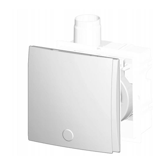
7 Ausblasadapter: Ausblas hinten • Fördervolumen 30 m³/h, 60 m³/h (kombiniert mit einer intelligenten Abdeckung auch 20 m³/h, 40 Abdeckungen: Abbildung mit ER-AB m³/h, 100 m³/h möglich). ER-A, ER-AH ER-AK ohne Abbildung • Einschaltverzögerung 60 s. 8 Abdeckung-Unterteil mit Zentralschraube • Nachlaufzeit 15 min. 9 G2-Luftfilter Für System- und Zubehörkomponenten mit nähe-... -
Page 5: Sicherheitshinweise
4 Sicherheitshinweise Die Ventilatoren können auch als Einzelgeräte ACHTUNG Gerätebeschädigung durch was- oder zur WC-Sitzentlüftung (nach DIN 18017-3) serdampfgesättigte oder fetthaltige Luft oder eingesetzt werden. anhaftende Feststoffpartikel. Die Ventilatoren sind ausschließlich für den häus- Wasserdampfgesättigte oder fetthaltige Luft oder lichen Gebrauch und ähnliche Zwecke vorgese- am Gerät anhaftende Feststoffpartikel können hen. - Page 6 4 Sicherheitshinweise GEFAHR Stromschlagegefahr bei Betrieb GEFAHR Gefahr durch Brandübertra- mit nicht komplett montiertem Gerät. gung. An elektrischen Komponenten besteht Strom- wenn am Gehäuse eine falsche Anschlussleitung schlaggefahr. angeschlossen ist. Verwenden Sie unbedingt die Bei offenem Gerät müssen alle Versorgungs- zum jeweiligen Gehäuse passenden Leitungsma- stromkreise abgeschaltet (Netzsicherung aus), terialien: Vorgaben gemäß...
-
Page 7: System- Und Produktinformationen
Schalldämmung beachten. 5.4 Kombinationsmöglichkeiten Planungshinweise bzgl. Geräteposition und Ab- ständen zu anderen Fassadenkomponenten be- achten. Eventuell Entkopplungselemente einsetzen. 5 System- und Produktinforma- tionen ER-A ER EC ER GH 5.1 Zulassungsbescheide ER-AH Zulassungsbescheide sind auf Anfrage erhältlich. ER-AK 5.2 Montagebedingungen ER-AB Bei einer Installation nach DIN 18017-3 ist ein... -
Page 8: Abdeckungen: Funktionen
• Mit Montagehalter oder den Montagenuten ein- fach im Schacht montierbar. Zubehör für Mon- tagehalter UPM 60/100 oder Montagenuten ER- MS (Montage-Set: je 4 Hammerkopfschrauben, Muttern und 90°-Winkel). 5.5 Abdeckungen: Funktionen ER-A ER-AK ER-AH ER-AB Filterwechselanzeige ● (6 Monate) mit TimeStrip Filterwechselanzeige ●... -
Page 9: Technische Daten
6 Technische Daten ER-A ER-AK ER-AH ER-AB Zusätzlich einstellbare Fördervolumen ● ●*** ● Grundlast: 20 m³/h, 40 m³/h, 60 m³/h oder 100 m³/h und Volllast 20 m³/h, 30 m³/h, 40 m³/h oder 100 m³/h Ein/Aus Volllaststufe über Lichtschalter oder separaten ● ● ● ● Schalter. Bei manueller Bedienung (z. B. per Lichtschal- ter) gilt die Einschaltverzögerung und Nachlaufzeit. -
Page 10: Lagerung
7 Montagevorbereitungen ER EC und ER-A 3/5 W* 6.4 Lagerung ER-AH, ER-AK, ER-AB 2/2,5/3/5/17W* Gerät nur in waagrechtem Zustand in einem ge- eigneten, trockenen Raum einlagern. Umgebung- Schutzart IP X5 stemperatur – 10 °C bis + 60 °C. Schalldruckpegel 19 bis 52 dB(A) Für Korrosionsschäden durch unsachgemäße Lagerung übernimmt die Maico Elektroapparate-... -
Page 11: Vorbereitungen Wandmontage
7 Montagevorbereitungen Zulassungsbestim- ER GH mung Wand-/Deckendurch- Mauerwerk oder Beton: bruch für Geräte-An- 130 mm schlussleitung DN 80 7.2 Vorbereitungen Wandmontage 12 Saugleitung für Zweitraumanschluss an ER ACHTUNG Gerätebeschädigung, Funktions- GH: Aluflexrohr AFR 75 / AFR 80 störung bei Korrosionsschäden durch Mörtel. An das Gerät angeschlossene Lüftungsleitungen 14 Hauptleitung: Stahlwickelfalzrohr zum Schutz vor Korrosion innerhalb des Mauer-... -
Page 12: Vorbereitungen Deckenmontage
7 Montagevorbereitungen 5. Zum Gehäuse passende Anschlussleitung an 7. Saugleitung verlegen und vorhandenen Rest- der Hauptleitung anschließen und lüftungs- spalt fachgerecht gemäß den vorigen Monta- technisch abdichten. gehinweisen verschließen. 6. Anschlussleitung ablängen, maximale Lei- 8. Netzleitung im Schacht verlegen und ca. tungslänge von 6 m beachten. - Page 13 7 Montagevorbereitungen Hauptleitung (Stahlwickelfalzrohr) Rohrbefestigung mit Rohrschelle, alternativ Rohrbefestigung mit Lochband Anschlussleitung ER GH: Aluflexrohr Geschossdecke Stahl-Gewindestange / Stockschraube Rohrbefestigung Rohrschelle / Lochband Deckenverguss Schachtwand Mauer-/Plattenbaustoff-Verschluss Abgehängte Decke Stahlschrauben oder Stahl-Blindniete (jeweils 3 Stück) Dübel 27.1 Kunststoffdübel oder Schlaganker 27.2 Metall-Spreizdübel Befestigungsschraube mit Mutter Zwischen den Rohrbefestigungen einen Ab- Befestigungsschraube...
-
Page 14: Vorbereitungen Für Den Elektri- Schen Anschluss
7 Montagevorbereitungen 3. Rohrbefestigungen an der Decke anbringen. 7.5 Vorbereitung Verschlussklappe Nur zulässiges Befestigungsmaterial verwen- ACHTUNG Mögliche Zufuhr von Gerüchen den. aus dem Lüftungskanal. Die Kunststoff-Verschlussklappe schließt bei GEFAHR Gefahr durch fehlerhafte Monta- falscher Einbaulage nicht dicht. ge bei unzulässigem Befestigungsmaterial. Verschlussklappe passend zur Einbaulage oben/ Anschlussleitung nur mit zulässigem Befesti- rechts/links/hinten in den Ausblasstutzen des Ge-... -
Page 15: Umbau Ausblasstutzen Für Ausblas Nach Hinten
7 Montagevorbereitungen Kunststoff-Verschlussklappe vorbereiten: Aus- Z Positionen blas nach oben, links oder rechts X 4 Arretierungsbolzen Wandmontage W 4 Bajonetthaken 1. Ausblasrichtung oben: Keine Veränderun- Y 4 Langlöcher gen vornehmen (Werkseinstellung). Vor dem Umbau die Verschlussklappe aus 2. Ausblasrichtung links oder rechts: Die Ver- dem Ausblasstutzen herausziehen. -
Page 16: Umbau Ausblasadapter Für Ausblas Nach Hinten
8 Gehäusemontage 7.7 Umbau Ausblasadapter für Aus- 8.2 Montagehinweise blas nach hinten (auch Vorgaben gemäß Zulassung [} 10]) Gehäuse ohne Brandschutzeinrichtung. 5 Spiralgehäuse Der Einbau ist in folgenden Einbaulagen zulässig: 6 Ausblasadapter: Ausblas oben (ab Werk) • Wandmontage: Mit Ausblasrichtung (Ausblas- 7 Ausblasadapter: Ausblas hinten stutzen) nach oben, rechts, links oder hinten. -
Page 17: Wichtige Hinweise Zum Verputzen
8 Gehäusemontage Zum Einsatz des Zweitraumanschluss-Set ER-ZR • Ein 50 bis 100 mm vertiefter Einbau ist mit dem oder des Absaugstutzens ER-AS das Gehäuse- zweiteiligem Mauerrahmen ER-MR ausgleich- segment [S] unten ausbrechen. bar. Der Anschluss einer WC-Sitzentlüftung am Ge- • Der vorhandene Restspalt zwischen Gehäuse häuse erfolgt mit dem Absaugstutzen ER-AS und Schacht muss mit formbeständigen, nicht (DN 75/80). -
Page 18: Deckenmontage Einraum
8 Gehäusemontage 3. Befestigungslöcher für Montagehalter an der GEFAHR Brandübertragung bei fehlerhaf- Schachtrückwand markieren, Bohrungen vor- tem Einbau der Anschlussleitung möglich. nehmen und Dübel einstecken. Geeignetes Befestigungsmaterial ist bauseitig bereitzustel- Nur zulässiges Leitungsmaterial verwenden (Vor- len. gaben gemäß Zulassung [} 10]). Die Anschlussleitung korrekt am Ausblasstutzen GEFAHR Kurzschlussgefahr und Geräte- anbringen. -
Page 19: Wandmontage Zweitraum
8 Gehäusemontage 4. Netzleitung von der Gehäuserückseite durch ACHTUNG Gerätebeschädigung und Funkti- Stufennippel in das Gehäuse einführen. onsstörung bei falschen / zu langen Befesti- 5. Gehäuse in die gewünschte Position bringen gungsschrauben. und mit bzw. ohne Montagehalter an der De- Befestigungsschrauben dürfen nicht in das Ge- cke befestigen. -
Page 20: Deckenmontage Zweitraum
8 Gehäusemontage 11.1 Montagestutzen Zweitraumabsaugung 8.7 Deckenmontage Zweitraum DN 75/80 1. Montagehinweise beachten: Montagehinweise 11.2 Adapter [} 16]. 11.3 Innengitter 2. Gehäuse wie beschrieben an der Decke mon- 11.4 G2-Filtermatte tieren: Deckenmontage Einraum [} 18]. Saugleitung Zweitraumanschluss: Aluflex- 3. Zweitraumanschluss-Set ER-ZR wie in be- rohr AFR 75/AFR 80 schrieben an der Decke montieren: Wand- Montagehalter UPM 60/100 oder ER-UPM... -
Page 21: Elektrischer Anschluss
9 Elektrischer Anschluss 9 Elektrischer Anschluss 16 Netzleitung ACHTUNG Gerätebeschädigung bei Kurz- schluss. 32 Stufennippel Schutzleiter und nicht benötigte Adern abschnei- 34 Klemmenleiste den und isolieren. GEFAHR Gefahr durch Stromschlag/Ge- Hinweise rätebeschädigung bei falschem Einbau auf- • Elektrischen Anschluss beim Einbau des Ge- grund zu langer Netzleitung. -
Page 22: Gerät Elektrisch Anschließen
10 Endmontage 9.1 Gerät elektrisch anschließen 1. Vor Zugang zu den Anschlussklemmen alle 4. Mantel der Netzleitung entfernen und ablän- Versorgungsstromkreise abschalten. Netzsi- gen: Elektrischer Anschluss [} 21]. cherung ausschalten, gegen Wiedereinschal- 5. Netzleitung an der Anschlussklemme gemäß ten sichern und ein Warnschild sichtbar an- Schaltbild elektrisch verdrahten: Schaltpläne. -
Page 23: Ventilatoreinsatz Anbringen
11 Absaugstutzen 10.1 Ventilatoreinsatz anbringen S Zentralschraube Für die Endmontage des Ventilatoreinsatzes 8 Abdeckung-Unterteil mit Zentralschraube ist kein Werkzeug erforderlich. 9 Luftfilter 1. Ventilatoreinsatz direkt auf die 3 Zapfen im In- 10 Abdeckung-Oberteil neren des Unterputzgehäuses stecken. Darauf achten, dass der Ventilatoreinsatz in allen 3 10.3 Tastensperre Schnappverschlüssen hörbar einrastet. -
Page 24: Gerät Bedienen
2. Das Anschlussrohr am Absaugstutzen und am tikfunktionen mit einstellbaren Geräteparametern: Abzweigstück im Spülrohr des Unterputz-Spül- Abdeckungen: Funktionen [} 8]. kastens anschließen. Dabei das Anschluss- • ER-A: Standardausführung rohr mit dem Absaugstutzen und Abzweig- • ER-AK: Komfortausführung stück dicht verbinden. • ER-AH: Ausführung mit Feuchtesteuerung, bar- 3. -
Page 25: System- Und Zubehörkomponenten
Weitere einstellbare Volumenströ- me: Grundlast 20 m³/h, 30 m³/h, 40 m³/h, 60 m³/ Luftfilter h oder 100 m³/h, Volllast 20 m³/h, 30 m³/h, 40 Ersatz-Luftfilter ZF EC+ für ER-A m³/h, 60 m³/h oder 100 m³/h Artikel-Nr. 0093.0610 • Montage- und Betriebsanleitung ER-Abdeckun- •... -
Page 26: Demontage
15 Demontage gen auf Mensch und Umwelt und ermöglicht eine Großpackung Ersatz-Luftfilter ZF EC+ für ER-A Wiederverwendung wertvoller Rohstoffe bei mög- Artikel-Nr. 0093.0611 lichst geringer Umweltbelastung. • 100x Ersatz-Luftfilter ZF EC+ (Filterklasse G2) Entsorgen Sie folgende Kompo- • 100x Filterwechselanzeige (TimeStrip) nenten nicht über den Hausmüll ! - Page 27 Table of contents 10.1 Attaching fan insert ......47 Table of contents 10.2 Fitting cover ........47 System overview........10.3 Key lock ..........47 Scope of delivery ........11 Extraction socket for WC odour ex- Specialist installer qualifications ..traction ............ Intended use...........
-
Page 28: System Overview
System overview System overview... -
Page 29: Scope Of Delivery
100 m³/h also possible if combined with an intelligent cover). Covers: Figure with ER-AB • Start delay 60 s. ER-A, ER-AH ER-AK not shown in figure • Overrun time 15 min. 8 Cover – lower part with central screw For system and accessory components with more... -
Page 30: Safety Instructions
4 Safety instructions The fans can be used as standalone units or for NOTICE Damage to the unit when continu- toilet seat air extraction (according to ously conveying steam-saturated air. DIN 18017-3). Never use unit to convey steam-saturated air The fans are only intended for domestic use and NOTICE Damage to the unit due to imbalance similar purposes. - Page 31 4 Safety instructions DANGER Danger if the relevant regula- WARNING Risk to health if filters are not tions for electrical installations are not ob- replaced or if there are no air filters. served. Heavily soiled or moist air filters can accumulate Before removing the housing cover or removing harmful substances (mould, germs, etc.).
-
Page 32: System And Product Information
In particular, note the information on ventilation channels and sound deadening. Observe planning instructions regarding unit pos- ition and distance to other façade components. If necessary, use isolating elements. ER-A ER EC ER GH ER-AH 5 System and product informa-... -
Page 33: Covers: Functions
• It is possible to rotate the cover by ± 5° to com- • Electrical plug connection for quick installation pensate for housings which have been fitted at in the housing. an angle. • Energy-saving EC motor. 5.5 Covers: Functions ER-A ER-AK ER-AH ER-AB Filter change indicator ● (6 months) with TimeStrip Filter change indicator ●... -
Page 34: Technical Data
6 Technical data Power frequency 50 Hz 6.1 Environmental conditions and op- Power consumption erating limits ER EC and ER-A 3/5 W* • Permissible maximum temperature of air me- ER-AH, ER-AK, ER-AB 2/2.5/3/5/17W* dium + 40 °C. Degree of protection IP X5 •... -
Page 35: Storage
Only store unit horizontally in a suitable, dry room. Ambient temperature – 10 °C to + 60 °C. Number of duct elbows Max. 2 x 90° Maico Elektroapparate-Fabrik GmbH accepts permitted for ceiling in- no liability for corrosion damage caused by im- stallation proper storage, e.g. -
Page 36: Preparations For Wall Installation
7 Mounting preparations 7.2 Preparations for wall installation 12 Suction duct for second room connection on Preparing the shaft ER GH: AFR 75 / AFR 80 flexible aluminium 1. Produce opening in shaft or alternatively pro- duct duce a wall facing. Ensure a suitable, flat sur- face for the housing so that the fan insert can 14 Main duct: Steel folded spiral-seams duct be safely inserted in the housing later on. -
Page 37: Ceiling Installation Preparations
7 Mounting preparations 8. Lay power cable in shaft and allow to protrude 9. Lay power cable: Electrically connecting the by around 30 cm above the shaft opening. unit [} 46]. 7.3 Ceiling installation preparations Preparing the shaft and suspended ceiling 12 Suction duct for second room connection on ER GH: AFR 75 / AFR 80 flexible aluminium 1. - Page 38 7 Mounting preparations Main duct (steel folded spiral-seams Duct attachment with duct clamp, alternatively duct) duct attachment with clamping band ER GH connection duct: Flexible alu- minium duct Floor ceiling Steel threaded rod / stair bolt Duct attachment Duct clamp / clamping band Ceiling compound Shaft wall Wall/wall board seal...
-
Page 39: Preparations For The Electrical Connection
7 Mounting preparations For wall installation with air outlet direction DANGER Risk of incorrect installation if (exhaust socket) to the left or right, install the non-permitted mounting material is used. shutter rotated by 90°, see following figures. Only secure connection duct to ceiling with per- mitted mounting material (duct clamp or clamping band). -
Page 40: Conversion Of Exhaust Socket For Air Outlet Towards Rear
7 Mounting preparations 4. Place the exhaust socket onto the housing 7.6 Conversion of exhaust socket for and push with the 4 bayonet hooks (at rear) to air outlet towards rear the right into the slots right up to stop. 5. -
Page 41: Housing Installation
8 Housing installation For air outlet direction to the rear, replace Housing without fire protection equipment. the air outlet adapter with the curved air out- Installation is permissible in the following installa- tion positions: let adapter. • Wall installation With air outlet direction (ex- Replacement haust socket) upwards, to the right, to the left or 1. -
Page 42: Wall Installation, Single Room
8 Housing installation 8.4 Wall installation, single room 3. Mark fixing holes for mounting support on rear 2 Exhaust socket with plastic shutter shaft wall, produce holes and insert dowels. 4 Plaster protective cover Suitable mounting material is to be provided 14 Main duct, steel folded spiral-seams duct by the customer. -
Page 43: Ceiling Installation, Single Room
8 Housing installation 9. Plaster in housing flush with front edge, note 7. Provide unit with electrical connection: Elec- tile thickness if necessary: Important informa- trically connecting the unit [} 46]. tion about plastering [} 41]. 8. Insert the plaster protective cover in the hous- ing. -
Page 44: Wall Installation, Second Room
8 Housing installation 6. Connect connection duct to exhaust socket DANGER Fire may spread if connection sealed for ventilation, e.g. with cold-shrink duct is incorrectly installed. tape. Only use permitted duct material (Requirements 7. Provide unit with electrical connection: Elec- in line with approval [} 35]). -
Page 45: Ceiling Installation, Second Room
9 Electrical connection 2. Mount housing on ceiling as described: Ceiling Suction duct, second room connection: AFR 75/AFR 80 flexible aluminium duct installation, single room [} 43]. UPM 60/100 or ER-UPM mounting sup- 3. Mount ER-ZR second room connection set on port ceiling, as described: Wall installation, second Housing segment room [} 44]. -
Page 46: Electrically Connecting The Unit
10 Final mounting • Only connect the unit to a permanent electrical • if the power cable is properly inserted through installation. the stepped grommet • The degree of protection is only guaranteed: • with the fan insert correctly engaged in the flush-mounted housing •... -
Page 47: Attaching Fan Insert
11 Extraction socket for WC odour extraction 10.1 Attaching fan insert S Central screw No tools are needed for the final assembly of 8 Cover – lower part with central screw the fan insert. 9 Air filter 1. Plug the fan insert directly into the 3 studs in 10 Cover –... -
Page 48: Operating The Unit
[} 33]. the concealed cistern. Make sure the connec- • ER-A: Standard model tions between the connection duct and the ex- traction socket and the branch are tight. • ER-AK: Comfort model •... -
Page 49: System And Accessory Components
20 m³/h, 30 m³/h, 40 m³/h, 60 Air filter m³/h or 100 m³/h, full load: 20 m³/h, 30 m³/h, 40 m³/h, 60 m³/h or 100 m³/h ZF EC+ replacement air filter for ER-A • Installation and operating instructions for ER Article no. 0093.0610 covers •... -
Page 50: Dismantling
• 2x replacement permanent filters for covers of the ER EC fan unit (filter class G2) Acknowledgements ZF ECD+ replacement permanent filter for ER- © Maico Elektroapparate-Fabrik GmbH. Trans- lation of the original operating instructions. Mis- prints, errors and technical changes are reserved. Article no. 0093.1562 The brands, brand names and protected trade •... - Page 51 Sommaire Branchement électrique ......71 Sommaire 9.1 Branchement électrique de l'appa- Vue d'ensemble du système....reil ............. Volume de fourniture......10 Montage final .......... 72 Qualification de l'installateur spéciali- 10.1 Montage de l'insert de ventilateur ..73 sé ............. 10.2 Placer le cache de protection.... 73 Utilisation conforme ......
-
Page 52: Vue D'ensemble Du Système
Vue d'ensemble du système Vue d'ensemble du système... -
Page 53: Volume De Fourniture
Insert de ventilateur ER EC (montage final) Caches de protection : figure avec ER-AB N° de réf. 0084.0360 ER-A, ER-AH ER-AK sans illustration • Ventilateur 2 niveaux à monter dans un boîtier encastré ER GH. 8 Partie inférieure cache de protection avec vis •... -
Page 54: Utilisation Conforme
3 Utilisation conforme électriques selon le Schémas des connexions AVERTISSEMENT Danger pour la santé dans les règles d'art et en toute sécurité, connaît par produits chimiques ou gaz / vapeurs les risques et dangers de l'électricité et sait les agressifs. éviter. Les produits chimiques ou gaz / vapeurs agres- 3 Utilisation conforme sifs risquent de nuire à... -
Page 55: Consignes De Sécurité Pour L'instal- Lation, Le Fonctionnement, Le Net- Toyage Et L'entretien
4 Consignes de sécurité 4.2 Consignes de sécurité pour l'ins- DANGER Danger en cas de non-respect tallation, le fonctionnement, le net- des consignes en vigueur relatives aux instal- lations électriques. toyage et l'entretien Avant de retirer le cache du boîtier ou le démon- tage de l'insert de ventilateur et avant l'installa- DANGER Danger pour les enfants et les tion électrique, couper tous les circuits d'alimen-... -
Page 56: Informations Sur Le Système Et Le Produit
5 Informations sur le système et le produit AVERTISSEMENT Danger pour la santé AVERTISSEMENT Risque de blessure et suite à des remplacements de filtres trop pour la santé en cas de modifications ou de rares ou à l'absence de filtres à air. transformations ou encore en cas d'utilisation Des filtres à... -
Page 57: Systèmes D'évacuation D'air Admis- Sibles
• Branchement électrique latéral ou arrière. Passe-câbles avec raccord cannelé. • Montage possible dans la gaine avec le support de montage ou les rainures de montage. Ac- ER-A ER EC ER GH cessoires pour support de montage UPM ER-AH... -
Page 58: Caches De Protection : Fonctions
(DIN VDE 0100-701). mation soufflage vers l'arrière. • Cache de protection orientable de ± 5°, ce qui permet de compenser l'encastrement de travers du boîtier. 5.5 Caches de protection : Fonctions ER-A ER-AK ER-AH ER-AB Affichage de remplacement de filtre ● (6 mois) avec timestrip Affichage de remplacement de filtre ●... -
Page 59: Caractéristiques Techniques
Fréquence du secteur 50 Hz fonction de la forme d'impulsion et de la propor- Puissance absorbée tion d'énergie de 1000 à 4000 V). En cas de ER EC et ER-A 3/5 W* fonctionnement avec tubes fluorescents, ces valeurs risquent d'être dépassées. Des me- ER-AH, ER-AK, ER-AB 2/2,5/3/5/17W* sures d'antiparasitage supplémentaires sont... -
Page 60: Stockage
7 Préparatifs de montage Pour des dommages de corrosion dus à un sto- Câble d'alimentation 3 x 1,5 mm² ckage non conforme, Maico Elektroapparate-Fa- secteur vers ER EC, brik GmbH déclinera tout recours en garantie, p. en fonction de la va- ex. -
Page 61: Préparatifs Montage Mural
7 Préparatifs de montage Clause d'agrément ER GH Passage dans mur / Maçonnerie ou béton : plafond pour gaine de 130 mm raccordement d'appareil DN 80 7.2 Préparatifs montage mural obturé avec des matériaux indéformables et 12 Gaine d'aspiration pour raccordement de non inflammables (p. ex. béton, mortier, mastic pièce secondaire sur ER GH : flexible alu réfractaire). -
Page 62: Préparatifs De Montage Au Plafond
7 Préparatifs de montage 3. Poser la gaine principale de ventilation à l'inté- Mesurer la longueur de la gaine de raccor- rieur de la gaine dans les règles de l'art. dement de manière à pouvoir la monter sur 4. Pour les systèmes de protection anti-incendie, le raccord de soufflage et à... - Page 63 7 Préparatifs de montage Gaine principale (tuyau agrafé en acier) Fixation de gaine ronde avec collier de serrage ou bien avec ruban perforé Gaine de raccordement ER GH : flexible Plancher Tige filetée en acier / Vis sans tête Fixation de gaine ronde Collier de serrage / Ruban perforé...
-
Page 64: Préparatifs Pour Le Branchement Électrique
7 Préparatifs de montage 3. Monter les fixations de gaines au plafond. 7.5 Préparation du volet de ferme- N'utiliser que du matériel de fixation admis- ture sible. ATTENTION Arrivée possible d'odeurs à partir DANGER Danger présenté par un mon- de la gaine de ventilation. tage défectueux en cas de matériel de fixation Le volet de fermeture en plastique n'est pas non admissible. -
Page 65: Transformation Raccord De Soufflage Pour Soufflage Vers L'arrière
7 Préparatifs de montage Préparer le volet de fermeture en plastique : Z Positions Soufflage vers le haut, la gauche ou la droite X 4 Boulons de verrouillage Montage mural W 4 crochets à baïonnette 1. Direction de soufflage vers le haut : ne rien Y 4 trous oblongs modifier (réglage usine). -
Page 66: Transformation Adaptateur De Souf- Flage Pour Soufflage Vers L'arrière
8 Montage du boîtier 7.7 Transformation adaptateur de 8 Montage du boîtier soufflage pour soufflage vers l'ar- 8.1 Montage du boîtier rière Non admissibles : • Utilisation d'un ventilateur ER EC dans la salle de bains ou le cabinet de toilette lorsque d'autres pièces de l'habitation doivent être aé- rées simultanément par le même appareil. -
Page 67: Remarques Importantes Relatives Au Crépissage
8 Montage du boîtier • Montage au plafond et sans faux plafond : Pour l'isolation acoustique des plafonds minces montage directement sur le plafond. résonants, utiliser du caoutchouc cellulaire ER- MO (Composants du système et accessoires Le matériel de fixation adéquat est à fournir par le client. - Page 68 8 Montage du boîtier 1. Retirer le couvercle de protection du crépi du 5. Placer le boîtier avec le support de montage boîtier. dans la gaine et le fixer à la paroi arrière de la gaine. ATTENTION Endommagement de l'appareil et dysfonctionnement en cas d'utilisation de vis DANGER Propagation d'incendie possible de fixation erronées / trop longues.
-
Page 69: Montage Au Plafond Pièce Unique
8 Montage du boîtier 2 Raccord de soufflage avec volet de fermeture DANGER Risque de court-circuit et d'en- en plastique dommagement de l'appareil. 4 Couvercle de protection du crépi Si le raccord cannelé n'est pas monté dans les 14 Gaine principale tuyau agrafé en acier règles de l'art, de l'eau peut pénétrer dans le boî- tier. -
Page 70: Montage Au Plafond Pièce Secon- Daire
8 Montage du boîtier 11.1 Raccord de montage pour aspiration d'une 8.7 Montage au plafond pièce secon- pièce secondaire DN 75/80 daire 11.2 Adaptateur 1. Respecter les consignes de montage : 11.3 Grille intérieure Consignes de montage [} 66]. 11.4 Élément filtrant G2 2. -
Page 71: Branchement Électrique
9 Branchement électrique 9 Branchement électrique 16 Câble secteur ATTENTION Endommagement de l'appareil en cas de court-circuit. 32 Raccord cannelé Couper et isoler le conducteur de protection et 34 Réglette de bornier les fils non utilisés. DANGER Danger par électrocution / En- Remarques dommagement de l'appareil suite à... -
Page 72: Branchement Électrique De L'appareil
10 Montage final 9.1 Branchement électrique de l'appareil 1. Avant d'accéder aux bornes de raccordement, 4. Retirer l'enveloppe du câble secteur et le couper tous les circuits d'alimentation élec- mettre à longueur : Branchement électrique trique. Désactiver le fusible secteur, sécuriser [} 71]. -
Page 73: Montage De L'insert De Ventilateur
11 Raccord d'aspiration 10.1 Montage de l'insert de ventila- teur S Vis centrale 8 Partie inférieure cache de protection avec vis centrale Pour le montage final de l'insert de ventila- 9 Filtre à air teur, aucun outil n'est nécessaire. 10 Partie supérieure cache de protection 1. -
Page 74: Utilisation De L'appareil
ER-AH, ER-AK, ER-AB dis- posent de fonctions automatiques avec para- mètres d'appareil réglables : Caches de protec- tion : Fonctions [} 58]. • ER-A : Version standard • ER-AK : Version confort • ER-AH : Version à commande en fonction de l'humidité, adaptée aux personnes handicapées... -
Page 75: Pièces De Rechange
• Adaptateur de soufflage avec soufflage vers Pendant le fonctionnement, prévoir une ar- l'arrière (transformable sans outils). rivée d'air suffisante. Cache de protection ER-A N° de réf. 0084.0361 13 Pièces de rechange • Version standard • Débits d'air de 30 m³/h / 60 m³/h Commande et montage des pièces de re-... -
Page 76: 15 Démontage
Le démontage ne doit être exécuté que par Filtre à air des électriciens qualifiés : Qualification de l'ins- Filtre à air de rechange ZF EC+ pour ER-A tallateur spécialisé [} 53]. N° de réf. 0093.0610 1. Avant d'accéder aux bornes de raccordement, •... - Page 77 3. Respectez les prescriptions nationales et lo- cales. Mentions légales © Maico Elektroapparate-Fabrik GmbH . Tra- duction du mode d'emploi d'origine en langue al- lemande. Sous réserve de fautes d'impression, d'erreurs et de modifications techniques. Les marques, marques commerciales et marques dé- posées, dont il est fait mention dans ce document...
- Page 78 Sadržaj 10.2 Montaža poklopca ......99 Sadržaj 10.3 Blokada tipki ........99 Pregled sustava ........79 11 Odsisna postolja........99 Opseg isporuke........80 12 Rukovanje uređajem ......100 Kvalifikacije stručnog instalatera..80 13 Rezervni dijelovi ........100 Odgovarajuća uporaba......80 14 Komponente sustava i pribora .....
-
Page 79: Pregled Sustava
Pregled sustava Pregled sustava... -
Page 80: Opseg Isporuke
• Volumen zraka 30 m³/h, 60 m³/h (u kombinaciji s pametnim poklopcem moguće i 20 m³/h, 40 Poklopci: Slika s ER-AB m³/h, 100 m³/h). ER-A, ER-AH ER-AK bez slike • Odgoda uključivanja 60 s. 8 Donji dio poklopca sa središnjim vijkom • Vrijeme naknadnog rada 15 min. -
Page 81: Sigurnosne Upute
4 Sigurnosne upute Ventilatori se također mogu koristiti kao PAŽNJA Oštećenje uređaja zbog masnih i pojedinačni uređaji ili za ventilaciju sjedala WC-a uljnih para iz kuhinjskih napa. (prema DIN 18017-3). Pare od masti i ulja iz kuhinjskih napa mogu Ventilatori su namijenjeni isključivo kućnoj onečistiti uređaj i zračne kanale i smanjiti uporabi i sličnim svrhama. - Page 82 4 Sigurnosne upute OPASNOST Opasnost pri nepridržavanju UPOZORENJE Opasnost za zdravlje zbog propisa koji su na snazi za električne neobavljene zamjene filtra ili nedostajućeg instalacije. zračnog filtra. Prije uklanjanja poklopca ili demontaže elementa Snažno onečišćeni ili vlažni zračni filtri mogu ventilatora i prije električnih instalacija isključite dovesti do nakupljanja tvari opasnih za zdravlje sve krugove strujnog napajanja, isključite mrežni...
-
Page 83: Informacije O Sustavu I Proizvodu
Posebno pazite na izvedbe ventilacijskih kanala i na zvučnu izolaciju. Upute za projektiranje koje se odnose na poziciju uređaja i razmake od drugih komponenti fasade. Eventualno koristite elemente za odspajanje. 5 Informacije o sustavu i ER-A ER EC ER GH proizvodu ER-AH ER-AK 5.1 Odluke o odobrenju... -
Page 84: Poklopci: Funkcije
• Može se izravno zavrnuti u predzid ili strop (4 područja 1 (DIN VDE 0100-701). dugačke rupe na vanjskom okviru). • Poklopac se može okretati za ± 5° za uravnoteženje koso žbukanog kućišta. 5.5 Poklopci: Funkcije ER-A ER-AK ER-AH ER-AB Indikacija zamjene filtra ●... -
Page 85: Tehnički Podaci
50 Hz skladu s normom EN 55014-2 (ovisno o obliku Apsorpcija struje impulsa i udjelu energije od 1000 do 4000 V). ER EC i ER-A 3/5 W* Pri radu sa svjetlosnim cijevima mogu se prekoračiti te vrijednosti. U tom slučaju ER-AH, ER-AK, ER-AB 2/2,5/3/5/17W* potrebne su dodatne mjere zaštite od smetnji... -
Page 86: Skladištenje
7 Pripreme za montažu U slučaju oštećenja uzrokovanih hrđanjem zbog nestručnog skladištenja Maico Elektroapparate- Glavni kabel prema ER 3 x 1,5 mm² Fabrik GmbH ne preuzima odgovornost, npr. pri EC, ovisno o varijanti skladištenju u vlažnom okruženju. uključivanja za ER-A, 5 x 1,5 mm²... -
Page 87: Pripreme Za Zidnu Montažu
7 Pripreme za montažu 7.2 Pripreme za zidnu montažu 12 Usisni vod za priključak za drugi prostor na Priprema okna ER GH: Cijev Aluflex AFR 75 / AFR 80 1. Postavite proboj okna ili kao drugu mogućnost 14 Glavni vod: Čelična spiralna šavna cijev predzid. -
Page 88: Pripreme Za Stropnu Montažu
7 Pripreme za montažu 8. Položite mrežni vod u okno i ostavite ga da 9. Polaganje mrežnog voda: Električno proviruje oko 30 cm iznad proboja okna. priključivanje uređaja [} 98]. 7.3 Pripreme za stropnu montažu Priprema okna i spuštenog stropa 12 Usisni vod za priključak za drugi prostor na ER GH: Cijev Aluflex AFR 75 / AFR 80 1. - Page 89 7 Pripreme za montažu Glavni vod (čelična spiralna šavna cijev) Cijevni pričvrsni element sa cijevnom obujmicom, kao drugo rješenje cijevni Priključni vod ER GH: Cijev Aluflex pričvrsni element s vrpcom s rupama Strop etaže Čelična navojna šipka/viseći vijak Cijevni pričvrsni element Cijevna obujmica/vrpca s rupama Stropni lijev Stijenka okna...
-
Page 90: Pripreme Za Električno Priključivanje
7 Pripreme za montažu 3. Postavite cijevne pričvrsne elemente na strop. 7.5 Priprema žaluzine Upotrebljavajte samo dopušteni materijal za PAŽNJA Moguć dovod mirisa iz ventilacijskog pričvršćivanje. kanala. Plastična žaluzina hermetički se ne zatvara u OPASNOST Opasnost zbog slučaju pogrešnog položaja za ugradnju. neodgovarajuće montaže pri nedopuštenom Umetnite žaluzinu tako da odgovara položaju za materijalu za pričvršćivanje. -
Page 91: Nadogradnja Odsisnog Postolja Za Stražnje Ispuhivanje
7 Pripreme za montažu Priprema plastične žaluzine: Ispuhivanje prema X 4 klina za blokiranje gore, lijevo ili desno W 4 bajunetne kuke Zidna montaža Y 4 dugačke rupe 1. Smjer ispuhivanja gore: Nemojte obavljati Prije nadogradnje izvucite žaluzinu iz izmjene (tvornička postavka). odsisnog postolja. -
Page 92: Nadogradnja Adaptera Za Stražnje Ispuhivanje
8 Montaža kućišta 7.7 Nadogradnja adaptera za stražnje 8.2 Upute za montažu ispuhivanje (također Specifikacije u skladu s odobrenjem [} 86]) 5 Spiralno kućište Kućište bez protupožarnog uređaja. 6 Adapter za ispuhivanje: Ispuhivanje gore Ugradnja je dopuštena u sljedećim položajima za (tvornički) ugradnju: 7 Adapter za ispuhivanje: Stražnje ispuhivanje... -
Page 93: Važne Napomene O Žbukanju
8 Montaža kućišta Kućište ne smije imati propuh kada se 8.3 Važne napomene o žbukanju umetne. Ako to nije slučaj, element ventilatora ne • Maks. uravnoteživo provirivanje žbuke iznosi 7 može ispravno sjesti u kućište i više nije zajamčena vrsta zaštite navedena na tipskoj •... -
Page 94: Stropna Montaža, Prvi Prostor
8 Montaža kućišta OPASNOST Opasnost od kratkog spoja i OPASNOST Moguć je prijenos požara pri oštećenja uređaja. pogrešnoj ugradnji priključnog voda. U slučaju nestručno ugrađenog stupnjevitog Upotrebljavajte samo dopušteni materijal za naglavka voda može prodrijeti u kućište. Vrsta pričvršćivanje (Specifikacije u skladu s zaštite u tom slučaju nije zajamčena. -
Page 95: Zidna Montaža, Drugi Prostor
8 Montaža kućišta 2. Za spuštene stropove prilagodite duljinu 5. Dovedite kućište u željeni položaj i pričvrstite montažnog držača, savijte ga i pričvrstite ga ga na strop montažnim držačem ili bez njega. isporučenim vijcima na kućište (Zidna OPASNOST Moguć je prijenos požara pri montaža, prvi prostor [} 93]). -
Page 96: Stropna Montaža, Drugi Prostor
8 Montaža kućišta 11.1 Montažni nastavci za odsisavanje drugog 8.7 Stropna montaža, drugi prostor prostora DN 75/80 1. Uzmite u obzir napomene o montaži: Upute za 11.2 Adapter montažu [} 92]. 11.3 Unutarnja rešetka 2. Ugradite kućište na strop kao što je opisano: 11.4 G2 uložak filtra Stropna montaža, prvi prostor [} 94]. -
Page 97: Električni Priključak
9 Električni priključak 9 Električni priključak 16 Mrežni vod PAŽNJA Oštećenje uređaja u slučaju kratkog spoja. 32 Stupnjeviti naglavak Odrežite i izolirajte zaštitne vodiče i nepotrebne 34 Stezna letvica žile. OPASNOST Opasnost od strujnog udara/ Napomene oštećenje uređaja pri pogrešnoj ugradnji zbog •... -
Page 98: Električno Priključivanje Uređaja
10 Završna montaža 9.1 Električno priključivanje uređaja 1. Prije pristupanja priključnim stezaljkama 4. Uklonite i skratite plašt mrežnog voda: isključite sve krugove za napajanje strujom. Električni priključak [} 97]. Isključite mrežni osigurač, zaštitite ga od 5. Električno spojite mrežni vod na priključnu ponovnog uključivanja i postavite vidljivu stezaljku u skladu s priključnom shemom: pločicu s upozorenjem. -
Page 99: Postavljanje Elementa Ventilatora
11 Odsisna postolja 10.1 Postavljanje elementa ventilatora S Središnji vijak 8 Donji dio poklopca sa središnjim vijkom 9 Zračni filtar Za završnu montažu elementa ventilatora nije potreban alat. 10 Gornji dio poklopca 1. Izravno nataknite element ventilatora na 3 10.3 Blokada tipki utična svornjaka u unutrašnjosti podžbuknog kućišta. -
Page 100: Rukovanje Uređajem
Pri tome zabrtvite i spojite namjestivim parametrima uređaja: Poklopci: priključnu cijev s odsisnim postoljem i Funkcije [} 84]. granskim komadom. • ER-A: Standardni model 3. Za montažu elementa ventilatora i poklopca → • ER-AK: Komforni model uputa Poklopci. • ER-AH: Model s regulacijom vlažnosti, bez barijere •... -
Page 101: Komponente Sustava I Pribora
Zračni filtar • Volumen zraka 30 m³/h / 60 m³/h u skladu s tvorničkom postavkom. Dodatni volumeni zraka Zamjenski zračni filtar ZF EC+ za ER-A koji se mogu namjestiti: Osnovno opterećenje Br. artikla 0093.0610 20 m³/h, 30 m³/h, 40 m³/h, 60 m³/h ili 100 m³/h, puno opterećenje 20 m³/h, 30 m³/h, 40 m³/h,... -
Page 102: Demontaža
Pridržavamo pravo tiskarskih pogrešaka, ventilatora ER EC (klasa filtra G2) pogrešaka i tehničkih izmjena. Marke, trgovačke Zamjenski trajni filtar ZF ECD+ za ER-A marke i zaštićene robne marke navedene u ovom Br. artikla 0093.1562 dokumentu odnose se na njihove vlasnike ili njihove proizvode. - Page 103 Spis treści 8.6 Montaż ścienny, pomieszczenie do- Spis treści datkowe..........Przegląd systemu ........104 8.7 Montaż sufitowy pomieszczenia do- Zakres dostawy ........105 datkowego......... Kwalifikacje fachowca instalatora..105 Przyłącze elektryczne ......124 Zastosowanie zgodne z przeznacze- 9.1 Podłączenie elektryczne urządzenia. 125 niem ............
-
Page 104: Przegląd Systemu
Przegląd systemu Przegląd systemu... -
Page 105: Zakres Dostawy
• Pokrywa zabezpieczająca na czas prac tynkar- trza skich Osłony: rysunek z ER-AB • Instrukcja montażu i eksploatacji ER-A, ER-AH ER-AK – brak rysunku Wkład wentylatora ER EC (montaż końcowy) Nr artykułu 0084.0360 8 Dolna część osłony ze śrubą centralną • 2-stopniowy wentylator do montażu w obudowie 9 Filtr powietrza G2 podtynkowej ER GH. -
Page 106: Zastosowanie Zgodne Z Przeznacze- Niem
3 Zastosowanie zgodne z przeznaczeniem tryk to osoba, która na bazie swego wykształce- NIEBEZPIECZEŃSTWO Istnieje zagroże- nia oraz ukończonych szkoleń i doświadczenia nie wybuchem spowodowanym przez poten- jest zaznajomiona z treścią odpowiednich norm cjalnie wybuchowe substancje znajdujące się i dyrektyw, umie wykonywać połączenia elek- w laboratoryjnych urządzeniach odsysają- tryczne w sposób profesjonalny i bezpieczny cych. -
Page 107: Wskazówki Dotyczące Bezpieczeństwa
4 Wskazówki dotyczące bezpieczeństwa UWAGA Istnieje niebezpieczeństwo uszko- NIEBEZPIECZEŃSTWO Niebezpieczeń- dzenia urządzenia na skutek niewyważenia stwo w przypadku nieprzestrzegania aktualnie wirnika podczas tłoczenia cząstek substancji obowiązujących przepisów dotyczących in- stałych. stalacji elektrycznych. Używanie urządzenia do tłoczenia przywierają- Przed przystąpieniem do zdjęcia osłony obudo- cych doń... - Page 108 4 Wskazówki dotyczące bezpieczeństwa NIEBEZPIECZEŃSTWO Istnieje niebezpie- OSTRZEŻENIE Wykonywanie później- czeństwo przeniesienia się pożaru. szych przeróbek lub montażu elementów do- w przypadku podłączenia do obudowy niewłaści- datkowych niesie ze sobą niebezpieczeństwo wego przewodu zasilającego. Należy koniecznie zranienia lub uszczerbku na zdrowiu. używać...
-
Page 109: Informacje O Systemie I Produkcie
5.4 Możliwości łączenia 5 Informacje o systemie i produk- 5.1 Świadectwa dopuszczenia Świadectwa dopuszczenia dostępne są na zapy- tanie. 5.2 Warunki montażu W przypadku instalacji wg DIN 18017-3 zasto- ER-A ER EC ER GH sowanie dopuszczalne jest wyłącznie: ER-AH • w jednostkowych instalacjach wyciągowych ze ER-AK wspólnym kanałem głównym. -
Page 110: Osłony: Funkcje
• Istnieje możliwość bezpośredniego mocowania • Możliwość obracania osłony o kąt ± 5° w celu śrubami do ściany przedniej lub sufitu (przez kompensacji nierównego osadzenia obudowy. 4 otwory podłużne w ramie zewnętrznej). 5.5 Osłony: Funkcje ER-A ER-AK ER-AH ER-AB Wskaźnik wymiany filtra ● (co 6 miesięcy) ze wskaźnikiem wymiany wkładu Wskaźnik wymiany filtra... -
Page 111: Dane Techniczne
6 Dane techniczne ER-A ER-AK ER-AH ER-AB Dodatkowa możliwość ustawiania wydajności powietrza ● ●*** ● Wydajność podstawowa: 20 m³/h, 40 m³/h, 60 m³/h lub 100 m³/h i pełna wydajność 20 m³/h, 30 m³/h, 40 m³/h lub 100 m³/h Włączanie/wyłączanie stopnia pełnej wydajności za po- ● ● ●... -
Page 112: Tabela Danych Technicznych
6.3 Tabela danych technicznych Napięcie znamionowe 230 V Częstotliwość sieci 50 Hz Pobór mocy 6.4 Przechowywanie ER EC i ER-A 3/5 W* Należy przechowywać urządzenie ustawione ER-AH, ER-AK, ER-AB 2/2,5/3/5/17 W* w pozycji poziomej w odpowiednim, suchym po- Stopień ochrony IP X5 mieszczeniu. -
Page 113: Przygotowania Montażu Ściennego
7 Przygotowania do montażu Świadectwo dopusz- ER GH Świadectwo dopusz- ER GH czenia czenia Przewody przyłączenio- Np. aluminiowy prze- Dopuszczalna liczba maks. 2 x 90° we usytuowane na ze- wód giętki AFR 80 mię- kolanek kanału przy wnątrz szybu dzy kanałem głównym montażu sufitowym w szybie a urządzeniem o długości maks. -
Page 114: Przygotowania Montażu Sufitowego
7 Przygotowania do montażu czeniowym a murem/płytowymi materiałami bu- 4. Nałożyć zaprawę stropową dla systemów dowlanymi/ścianą/sufitem za pomocą stabil- ochrony przeciwpożarowej. W tym celu ode- nych wymiarowo, niepalnych materiałów bu- skować sufit i wlać materiał od góry. dowlanych (np. betonu, zaprawy cementowej, 5. Podłączyć do kanału głównego przewód prze- ognioodpornej masy szpachlowej). - Page 115 7 Przygotowania do montażu Przygotowanie szybu i sufitu podwieszonego 12 Przewód ssawny do przyłączania pomiesz- czenia dodatkowego do ER GH: Aluminiowy 1. Wykonać przepust w suficie podwieszanym. przewód giętki AFR 75 / AFR 80 2. Wykonać w szybie przepust do przewodu 14 Kanał główny: stalowy przewód ze szwem przyłączeniowego DN 75 lub DN 80.
-
Page 116: Przygotowania Do Podłączenia Elektrycznego
7 Przygotowania do montażu 6. Zamontować sufit podwieszony. W przypadku Mocowanie rury za pomocą opaski rurowej, al- obudowy zadbać o dopasowane, płaskie pod- ternatywnie mocowanie rury za pomocą taśmy łoże, aby później możliwe było bezpieczne perforowanej osadzenie wkładu wentylatora w obudowie. 7. Ułożyć przewód sieciowy: Podłączenie elek- tryczne urządzenia [} 125]. -
Page 117: Przeróbka Króćca Wylotowego Na Wydmuch Powietrza W Tył
7 Przygotowania do montażu 7.6 Przeróbka króćca wylotowego na wydmuch powietrza w tył Przygotowanie żaluzji z tworzywa sztucznego: wydmuch powietrza w górę, lewo lub prawo Montaż ścienny 3 Żaluzja 1. Kierunek wydmuchu w górę: Nie dokonywać żadnych zmian (ustawienie fabryczne). Z Pozycje 2. Kierunek wydmuchu w lewo lub prawo: Wy- X 4 sworznie blokujące ciągnąć... -
Page 118: Przeróbka Adaptera Wydmuchowe- Go Na Wydmuch Powietrza W Tył
8 Montaż obudowy 3. Rys. dolny: Obrócić króciec wylotowy tak, by 6 Adapter wydmuchowy: górny wydmuch po- był skierowany w tył. wietrza (wersja fabr.) 4. Założyć króciec wylotowy na obudowę, po 7 Adapter wydmuchowy: tylny wydmuch powie- czym przesunąć go w prawo do oporu za po- trza mocą... -
Page 119: Ważne Wskazówki Dotyczące Tynko- Wania
8 Montaż obudowy • Montaż sufitowy a sufit niepodwieszany: Montaż bezpośrednio na suficie. Odpowiednie elementy mocujące zapewnia inwe- stor. Żaluzję z tworzywa sztucznego należy przygo- tować zgodnie z niniejszą instrukcją, aby za- mykała się szczelnie w pozycji montażowej. Obudowa musi być osadzona w sposób unie- możliwiający jej odkształcenie. -
Page 120: Montaż Ścienny, Jedno Pomieszczenie
8 Montaż obudowy 8.4 Montaż ścienny, jedno pomieszczenie 2. Przyciąć uchwyt montażowy na odpowiednią 2 Króciec wylotowy z żaluzją z tworzywa długość, wygiąć go i przymocować na obudo- sztucznego wie przy użyciu dołączonych śrub mocujących. 4 Pokrywa zabezpieczająca na czas prac tyn- 3. Zaznaczyć na tylnej ścianie szybu otwory do karskich zamocowania uchwytu montażowego, wyko- 14 Kanał... -
Page 121: Montaż Sufitowy, Jedno Pomieszcze
8 Montaż obudowy 6. Przewód przyłączeniowy musi być szczelnie NIEBEZPIECZEŃSTWO Możliwość roz- połączony z króćcem wylotowym, np. przy przestrzeniania się ognia na skutek wadliwe- użyciu opaski obkurczanej na zimno. go montażu przewodu przyłączeniowego. 7. Podłączenie elektryczne urządzenia: Podłą- Używać tylko dopuszczonych materiałów przewo- czenie elektryczne urządzenia [} 125]. -
Page 122: Montaż Ścienny, Pomieszczenie Dodatkowe
8 Montaż obudowy 2. Do sufitów podwieszonych przyciąć uchwyt 5. Umieścić obudowę w żądanym położeniu i za- montażowy na odpowiednią długość, wygiąć mocować na suficie z użyciem uchwytu mon- go i zamocować na obudowie za pomocą za- tażowego lub bez niego. łączonych śrub (Montaż ścienny, jedno po- NIEBEZPIECZEŃSTWO Możliwość... -
Page 123: Montaż Sufitowy Pomieszczenia Dodatkowego
8 Montaż obudowy 11.1 Króciec montażowy wyciągu powietrza 8.7 Montaż sufitowy pomieszczenia z dodatkowego pomieszczenia DN 75/80 dodatkowego 11.2 Adapter 1. Przestrzegać wskazówek montażowych: 11.3 Kratka wewnętrzna Wskazówki montażowe [} 118]. 11.4 Mata filtracyjna G2 2. Zamontować obudowę na suficie w sposób Przewód ssawny do przyłączenia dodat- opisany w: Montaż... -
Page 124: Przyłącze Elektryczne
9 Przyłącze elektryczne 9 Przyłącze elektryczne 16 Przewód sieciowy UWAGA Uszkodzenie urządzenia na skutek nieprawidłowego podłączenia. 32 Złączka stopniowa Na przykład w przypadku podłączenia obciążenia 34 Listwa zaciskowa elektrycznego do zacisku 4 lub podłączenia do 2 faz. NIEBEZPIECZEŃSTWO Istnieje niebezpie- Podłączyć urządzenie w sposób zgodny ze sche- czeństwo porażenia prądem elektrycznym / matami połączeń: Schematy połączeń. -
Page 125: Podłączenie Elektryczne Urządzenia
10 Montaż końcowy • prawidłowego zatrzaśnięcia wkładu wentyla- • przykręcenia, zamknięcia i zatrzaśnięcia osło- tora w obudowie podtynkowej 9.1 Podłączenie elektryczne urządzenia 1. Przed rozpoczęciem prac przy zaciskach przy- 4. Usunąć płaszcz z przewodu sieciowego, po łączeniowych należy wyłączyć wszystkie zasi- czym przyciąć przewód na odpowiednią dłu- lające obwody prądowe. -
Page 126: Montaż Wkładu Wentylatora
11 Króciec odsysający 10.1 Montaż wkładu wentylatora S Śruba centralna Wykonanie montażu końcowego wkładu wen- 8 Dolna część osłony ze śrubą centralną tylatora nie wymaga stosowania narzędzi. 9 Filtr powietrza 1. Należy założyć wkład wentylatora bezpośred- 10 Górna część osłony nio na 3 rozpórki znajdujące się... -
Page 127: Obsługa Urządzenia
AB posiadają funkcje automatyczne z ustawiany- 3. Montaż wkładu wentylatora i osłony → instruk- mi parametrami: Osłony: Funkcje [} 110]. cja osłon. • ER-A: Wersja standardowa • ER-AK: Wersja komfortowa • ER-AH: Wersja z funkcją sterowania zależnego od wilgotności, bez barier • ER-AB: Wersja z czujnikiem ruchu, bez barier W trybie pracy z pełną... -
Page 128: Komponenty Systemowe I Akcesoria
• Adapter wydmuchowy z tylnym wydmuchem powietrza (przeróbka nie wymaga stosowania • Służy do mocowania obudowy za pomocą śrub narzędzi). z łbem młoteczkowym lub montażowych. Osłona ER-A Zestaw do przyłączania pomieszczenia dodat- Nr artykułu 0084.0361 kowego ER-ZR • Wersja standardowa Nr artykułu 0093.1025 •... -
Page 129: Demontaż
• Do zbyt głęboko zatynkowanej lub zamontowa- • 10 x wskaźnik wymiany filtra (wskaźnik wymia- nej obudowy. ny wkładu) Filtr powietrza Wymienny filtr powietrza ZF EC+ do ER-A 15 Demontaż Nr artykułu 0093.0610 Demontaż może być wykonywany wyłącznie • 5 x wymienny filtr powietrza ZF EC+ (klasa filtra przez wykwalifikowanego technika-elektryka: Kwalifikacje fachowca instalatora [} 105]. - Page 130 3. Należy przestrzegać odpowiednich przepisów krajowych i lokalnych. Stopka redakcyhna © Maico Elektroapparate-Fabrik GmbH . Tłu- maczenie na język polski oryginalnej niemieckiej instrukcji eksploatacji. Nie ponosimy odpowie- dzialności za błędy drukarskie, pomyłki i zmiany techniczne. Marki, znaki handlowe i chronione znaki towarowe wymienione w niniejszym doku-...
- Page 131 • ER-AH : Commande en fonction de l'humidité • ER-AB : Détecteur de mouvement Pour cache de protection ER-A : • temporisation de démarrage 60 secondes • Durée de fonctionnement par temporisation 15 minutes Tolerancije za navedena vremena = nazivna vrijednost ± 5 %...
-
Page 132: Anschlussvariante Grundlast/Voll
Schaltbilder / Wiring diagrams / Schémas de branchement / Priključne sheme / Schematy połączeń Anschlussvariante Grundlast/Volllast / Ba- se load/full load connection variant / Vari- ER-A Standard cover antes de raccordement charge de base/ ER-AH Humidity covers (optional) charge pleine pour / Varijante priključka Motor control osnovno opterećenje/puno opterećenje /... - Page 133 Commande du moteur wość włączania wydajności znamionowej przy ciągłej pracy w trybie obciążenia podstawowego ER-A (standardno) ER-AH (opcija) Upravljanje motorom ER-A (standard) ER-AH (opcjonalnie) Układ sterowania silnikiem ER-A (Standard) ER-AH (Optional) Motorsteuerung ER-A Standard cover ER-AH Humidity covers (optional) Motor control...
- Page 134 / Możliwość włączenia ER-AH (en option) wydajności podstawowej i znamionowej Commande du moteur ER-A (standardno) ER-AH (opcija) Upravljanje motorom ER-A (standard) ER-AH (opcjonalnie) Układ sterowania silnikiem ER-A (Standard) ER-AH (Optional) Motorsteuerung ER-A Standard cover ER-AH Humidity covers (optional) Motor control...
-
Page 135: Anschlussvariante Feuchte
Schaltbilder / Wiring diagrams / Schémas de branchement / Priključne sheme / Schematy połączeń Anschlussvariante Feuchte / Humidity connection variant / Variantes de raccor- ER-AH (en option) dement humidité / Varijanta priključka Commande du moteur vlažnost / Warianty podłączenia – tryb wilgotność... - Page 136 Maico Elektroapparate-Fabrik GmbH Steinbeisstr. 20 78056 Villingen-Schwenningen Deutschland Service +49 7720 6940 info@maico.de 0185.1224.0001_RLF.9_03.22_DSW-AS_Multi...
Need help?
Do you have a question about the ER-A and is the answer not in the manual?
Questions and answers