
Related Manuals for Leviton 2000 Series


Summary of Contents for Leviton 2000 Series
- Page 1 Models beginning with 2M, 2L or 2X Series 2000 Multiple Meter Units (MMUs) Product Description Technical Specifications Installation Instructions February 28 , 2013...
-
Page 2: Table Of Contents
3.6 Installation of Voltage Lines....................19 3.7 Variations and Installation of Current Transformers ............20 3.8 Testing the Installation......................24 4. Maintenance............................24 4.1 Adding Meters to an Existing Installation ................24 5. Troubleshooting/FAQ..........................25 6. Contact Information..........................27 Leviton Manufacturing Co., Inc. Contents... - Page 3 1. Product Description General Description The Leviton Series 2000 Meter is a self-powered, current transformer (CT) rated electronic kilowatthour (kWh) meter designed for permanent connection to an electrical service. Series 2000 meters are compatible with a variety of service configurations to fit many applications.
-
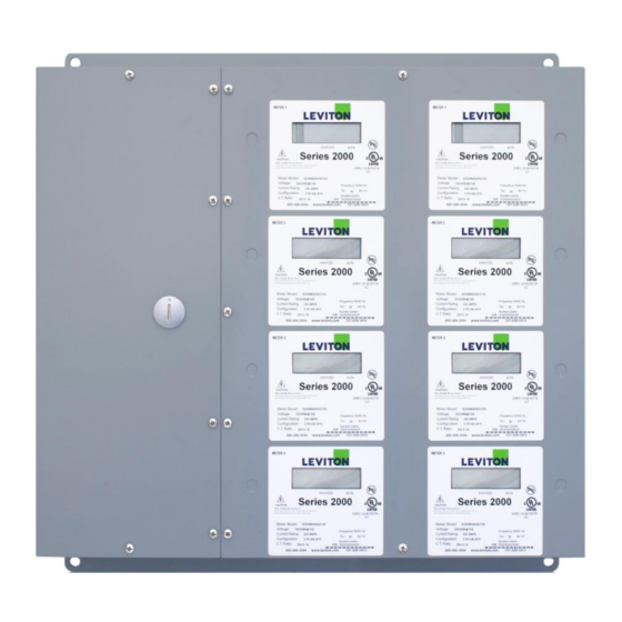
Page 4: Meter Certifications
(see Section 4.1). Figures 1, 2, and 3 below show the dimensions of the small, medium and large MMU enclosures respectively. Leviton Manufacturing Co., Inc. 3.0 Installation Instructions... - Page 5 Series 2000 MMU Installation Manual Figure 1: Medium MMU Enclosure Dimensions Leviton Manufacturing Co., Inc. 3.0 Installation Instructions...
- Page 6 Series 2000 MMU Installation Manual Figure 2: Large MMU Enclosure Dimensions Leviton Manufacturing Co., Inc. 3.0 Installation Instructions...
- Page 7 Series 2000 MMU Installation Manual Figure 3: X-Large MMU Enclosure Dimensions Leviton Manufacturing Co., Inc. 3.0 Installation Instructions...
-
Page 8: Technical Specifications
The electrical and environmental specifications for Series 2000 meters are given in Table 1 below. Table 1: Series 2000 electrical specifications Accuracy based on Leviton solid core current transformers (included), with 100 mA secondary output. Meter input burden resistance at 2 Ohm ²... -
Page 9: Input/Output Connections
2.2 Input/Output Connections and User Display The input and output terminals for Series 2000 meters are shown below in the Figure below. For hookup diagrams and wiring information refer to section 3. Figure 1: Series 2000 terminals Leviton Manufacturing Co., Inc. 3.0 Installation Instructions... - Page 10 Series 2000 MMU Installation Manual Leviton Manufacturing Co., Inc. 3.0 Installation Instructions...
-
Page 11: Display Specifications
This back and forth transition triggers a demand reset. The maximum transition period is one second. Multiple key switch transitions during the peak demand display interval may be required to reset peak demand. Leviton Manufacturing Co., Inc. 3.0 Installation Instructions... -
Page 12: Installation Instructions
The following section contains installation and wiring instructions for the Leviton Series 2000 multiple meter unit. If technical assistance is required at any point during the installation, contact information can be found at the end of this manual. Leviton is not responsible for damage to the meter caused by incorrect wiring. -
Page 13: Preparation
Wires must be 18 AWG or larger and insulated for 600 VAC min. Current Transformers (CTs): This product is designed for use with Leviton CTs Conduit and fittings appropriate for MMU knockout size. 3.5 Mounting the Enclosure 3.5.1 Selecting a Mounting Location... -
Page 14: Installation Of Voltage Lines
.300 inches if needed and connect to the appropriate terminals. Wires should be tightened so that they are held snuggly in place, but do not to over-tighten, as this may compress and weaken the conductor. Leviton Manufacturing Co., Inc. 3.0 Installation Instructions... - Page 15 ‘in phase’ for accurate readings (e.g. CT1 on Line 1, CT2 on Line 2). For 3 Ph 4-wire electrical panels, see Figure 12 and follow factory-provided meter schedules for correct CT locations. Leviton solid core CTs Installing solid core CTs 1. Route CT wires through the conduit if not already done.
- Page 16 Series 2000 MMU Installation Manual Series 2000 Multiple Meter Cabinet Single Phase, 3 wire hookup diagram Leviton Manufacturing Co., Inc.
- Page 17 Series 2000 MMU Installation Manual Series 2000 Multiple Meter Cabinet 3-Phase, 4 wire hookup diagram Leviton Manufacturing Co., Inc.
-
Page 18: Testing The Installation
From this description, it is possible to determine if the kWh and/or demand values displayed on the LCD are consistent with the applied load. A load must be applied for the kWh value to show significant changes. Leviton Manufacturing Co., Inc. -
Page 19: Maintenance
Properly installed meters with sound connections and secure conduit fittings should not require user maintenance. If the meter is functioning abnormally, consult the FAQ/Troubleshooting guide. If the answer cannot be found there, contact Leviton technical support. 4.1 Adding Meters to an Existing Installation MMUs ordered with less than the maximum number of meters can also be ordered with preinstalled expansion slots. -
Page 20: Troubleshooting/Faq
Verify orientation and connection of CT 4. Reverse phase LED illuminated wires Ensure that phasing is correct (CT1 on Line 1, CT2 on Line 2) Verify that a load drawing more than 1 Amp is connected to the meter Leviton Manufacturing Co., Inc. -
Page 21: Contact Information
Leviton S. de R.L. de C.V. Lago Tana 43, Mexico DF, Mexico CP 11290 • Tel. (+52) 55-5082-1040 • www.leviton.com.mx Visit our Website at www.leviton.com/les © 2012 Leviton Manufacturing Co., Inc. All rights reserved. Subject to change without notice. Leviton Manufacturing Co., Inc.
Need help?
Do you have a question about the 2000 Series and is the answer not in the manual?
Questions and answers