Leviton Series 2000 Manuals
Manuals and User Guides for Leviton Series 2000. We have 3 Leviton Series 2000 manuals available for free PDF download: Installation Manual, Installation Instructions Manual
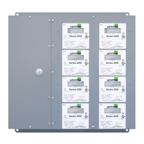
Leviton Series 2000 Installation Manual (69 pages)
Brand: Leviton
|
Category: Measuring Instruments
|
Size: 3 MB
Table of Contents
Advertisement
Leviton Series 2000 Installation Manual (69 pages)
Brand: Leviton
|
Category: Measuring Instruments
|
Size: 0 MB
Table of Contents
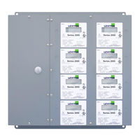
Leviton Series 2000 Installation Instructions Manual (21 pages)
Multiple Meter
Brand: Leviton
|
Category: Measuring Instruments
|
Size: 0 MB
Table of Contents
Advertisement
Advertisement