Advertisement
Table of Contents
- 1 Table of Contents
- 2 Warnings and Cautions
- 3 Introduction
- 4 Planning for Field Installation
- 5 Meter Configuration
- 6 Meter Installation
- 7 Communication & Verification
- 8 RTU Programming & Scripting
- 9 Appendix A: LCD Menu Navigation
- 10 Appendix B: Technical Specifications
- 11 Standard Statements and Warranty
- Download this manual
Advertisement
Table of Contents

Related Manuals for Leviton 7000 Series


Summary of Contents for Leviton 7000 Series
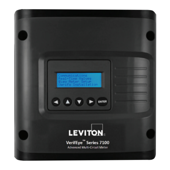
- Page 1 ® VerifEye Advanced Multi-Circuit Meter 7000/7100 Series User's Guide Cat. Nos. 71D12, 71D48, 70D12, 70D48, 70N12, 70N48, 71D24, 70D24, 70N24, 71D03, 70D03 Cat. 71D12 Cat. 71D24 and 71D48 Cat. 70D12 Cat. 70D48 Cat. 70D03 Cat. 70D24 Cat. 71D03 PK-A3259-10-00-0D...
-
Page 3: Table Of Contents
TABLE OF CONTENTS 1 Warnings and Cautions ..............4 2 Introduction ..................6 3 Planning for Field Installation ............9 4 Meter Configuration ................. 11 5 Meter Installation ................23 6 Communication & Verification ............36 7 RTU Programming & Scripting............48 8 Appendix A: LCD Menu Navigation ..........62 9 Appendix B: Technical Specifications ..........65 10 Standard Statements and Warranty ..........67... -
Page 4: Warnings And Cautions
WARNINGS AND CAUTIONS WARNINGS: • HAZARD OF ELECTROCUTION, SHOCK, EXPLOSION, OR ARC FLASH. CAREFULLY READ AND FOLLOW INSTRUCTIONS. • TO AVOID FIRE, SHOCK OR DEATH, turn OFF all power supplying equipment before working on or inside the equipment. Use a properly rated voltage sensing device to confirm power is OFF. - Page 5 • Do no use any cleaning agents, including water, on the device. • No accessories are approved for use with the meter other than those specified in the Leviton Manufacturing product literature and price sheets. • A circuit breaker used as a disconnect must meet the requirements of IEC 60947-1 and IEC 60947-3 (Clause 6.11.4.2).
-
Page 6: Introduction
INTRODUCTION The VerifEye ® 7000 Series and the VerifEye ® 7100 Series meters monitor the voltage, current, power, energy, and many other electrical parameters on single and three-phase electrical systems. A VerifEye ® meter uses direct connections to each phase of the voltage and current transformers to monitor each phase of the current. - Page 7 INTRODUCTION 2.2 Meter Anatomy All user connections are made on the circuit board. Connectors are identified by function and include polarity markers. Cat. 71D12 Series 7100 Branch Circuit Monitor, Plastic Enclosure 12 Input, with LCD Display Mounting Hole (6) Pulse Input 1 & 2 CT Inputs Voltage Cover (transparent)
- Page 8 INTRODUCTION 71D03 Series 7100 3-Phase Meter, Wall Mount Plastic Enclosure, with LCD Display 70D03 Series 7000 3-Phase Meter, DIN Rail Mount Plastic Enclosure, with LCD Display CT Connections (x3) RS-485 Bare (RŌC) (S) Black or Brown (-) White (+)
-
Page 9: Planning For Field Installation
PLANNING FOR FIELD INSTALLATION 3.1 Project Manager Aspects Meter installation often includes coordination between individuals or groups of people with different responsibilities. Spend a few minutes considering who will be executing each portion of the installation and what tools are needed at each stage. - Page 10 • Establish communication with meter. • Thumb Drive (Power Meter Viewer Utilities • Firmware update (if required) Installer) or access www.Leviton.com, and go to software downloads for this product. • Configure software for anticipated meter setup. • Electrical schematics of project •...
-
Page 11: Meter Configuration
4.1 Install the Power Meter Viewer Utilities Software Insert the Power Meter Viewer Utilities thumb drive into the computer or download it from the Leviton FTP site (qualified Leviton personnel only). The installer starts automatically. If it does not, browse the thumb drive and locate the Setup.exe program, double-click it, and follow the installer instructions. - Page 12 METER CONFIGURATION 4.1.2 USB Connection (Power and Communications) ® 1. Connect the VerifEye meter to a USB port on your computer to provide both power and communications. a. If equipped, the LCD display is the most visible indication of a running meter.
- Page 13 METER CONFIGURATION 4.1.5 Direct Connection When a PC is directly connected to a VerifEye ® meter via an Ethernet cable, no DHCP service exists. This configuration can be made to work, but requires changes to either the meter communication settings or the PC network configuration.
- Page 14 METER CONFIGURATION 4.1.6 Network Scan Network Scan is a feature for monitoring previously installed and configured ® VerifEye meters over an Ethernet network. Network Scan broadcasts a UDP discovery packet on the same network as the PC that runs the Power Meter Viewer Utilities application.
- Page 15 METER CONFIGURATION 4.2 Power Meter Viewer Utilities Software Overview Power Meter Viewer Utilities is a Windows application, and is used to configure ® and verify a VerifEye meter. All functions and menus are accessed under the central drop-down list, which has a content filter for viewing Basic metering data or Extended meter data that can be helpful in troubleshooting.
- Page 16 METER CONFIGURATION 4.2.1 Configuring Electrical Components Using Power Meter Viewer Utilities 1. Navigate to Meter Setup under the Display Menu List Box. 2. Enter a System Description for the physical location of the meter. 3. Enter Element Description (defaults are A, B, etc.). 4.
- Page 17 METER CONFIGURATION 4.2.2 Configuring RS-485 Communications Using Power Meter Viewer Utilities If planning to setup communication via RS-485, follow the steps below: 1. Navigate to Communication Setup under Display Menu List Box. 2. Select RS-485. 3. Select either Modbus or BACnet. If you selected Modbus, set the following: •...
- Page 18 METER CONFIGURATION 4.2.3 Configuring Ethernet Communications Using Power Meter Viewer Utilities If planning to setup communication via Ethernet, follow the steps below. 1. Navigate to Communication Setup under the Display Menu List Box. 2. Select Ethernet. 3. Select either Modbus or BACnet. 4.
- Page 19 METER CONFIGURATION 4.2.4 Configuring Alarms in Power Meter Viewer Utilities ® The VerifEye power meter has the ability to set alarms for over and under conditions for voltage and current on any meter channel. Configuration Input Methods Power Meter Viewer Utilities uses dynamic entry for the specification of Alarm settings.
- Page 20 METER CONFIGURATION 4.2.5 Setting the Real Time Clock The VerifEye ® meter includes a Real Time Clock. The clock is used only to time stamp Interval Data in the log. It is not used for calculation within the meter. For those customers using the IDR function of the meter, it is helpful (but not necessary) to set the real time clock so that data records can be uniquely identified.
- Page 21 METER CONFIGURATION 4.2.6 Retrieving Interval Data The VerifEye ® meter maintains an internal log of the energy data (Net kWh) for each channel in the meter. This log updates every 15 minutes, and is always active. The meter stores 63 days’ worth of 15 minute data in its memory.
- Page 22 METER CONFIGURATION 4.3 VerifEye ® Web App Overview ® The VerifEye meter hosts a Web Application that can be accessed by any smart ® device running a web browser. You can access the VerifEye Web App via the USB or Ethernet port. NOTE: •...
-
Page 23: Meter Installation
METER INSTALLATION This section describes the physical installation of the meter and provides guidance on connecting the current transformers (CTs) correctly within the electrical load center and to the VerifEye ® meter. 5.1 Meter Mounting Configurations ® VerifEye meters are sold in several form factors. Enclosures are designed to be wall mounted and connected to electrical conduit. - Page 24 METER INSTALLATION 5.2 Installation Sequence For enclosure models only. 1. Remove covers. Screws are provided. Cat. 71D12 Cat. 71D48 and 71D24 Cat. 71D03...
- Page 25 METER INSTALLATION 2. Mount. Use the enclosure as a template. NOTE: If meter is not available to use as a template, see the mechanical specifications drawing in the appendix. Cat. 71D12 Cat. 71D48 and 71D24 Cat. 71D03...
- Page 26 METER INSTALLATION 3. Connect. • Conduit fittings • Conduits • Blanking plugs Cat. 71D48 Cat. 71D12 Cat. 71D03 4. Connect voltage leads. WARNING: RISK OF ELECTROCUTION, SHOCK, EXPLOSION, OR ARC FLASH. DO NOT ENERGIZE METER WITH VOLTAGE COVER REMOVED. CAREFULLY READ AND FOLLOW INSTRUCTIONS. Connect the voltage leads (L1, L2, L3, and N as necessary) to the meter through a dedicated disconnect or circuit breaker.
- Page 27 METER INSTALLATION Cat. 71D48 Cat. 71D03...
- Page 28 METER INSTALLATION 5. Attach high-voltage cover. NOTE: IP30 TouchS f (with internal cover installed). Cat. 71D12 Cat. 71D48 and 70D48 Cat. 71D03...
- Page 29 METER INSTALLATION 6. Connect CT and communications wiring. Cat. 71D12 Cat. 71D48 Cat. 71D03...
- Page 30 METER INSTALLATION 5.3 Installation Sequence for 70D03 This section illustrates the 70D03 model, which is equipped with a built-in DIN rail channel for easy installation. The 70D03 must be installed inside a UL approved electrical enclosure. 35mm T35 DIN Rail 1.
- Page 31 METER INSTALLATION 4. Reattach the high-voltage cover. 5. Connect CT and communications wires. CT Connections (x3) RS-485 Bare (RŌC) (S) Black or Brown (-) USB-C Ethernet White (+) Connecting Voltage Connect the voltage leads (L1, L2, L3, and N, as necessary) to the meter through a dedicated disconnect or circuit breaker.
- Page 32 METER INSTALLATION 5.4 Wiring in a 3-Wire, Split-Phase Service Panel WARNINGS: • TO AVOID FIRE, SHOCK, OR DEATH; TURN OFF POWER at circuit breaker or fuse and test that power is OFF before wiring! • HIGH-VOLTAGE WIRES MAY BE PRESENT. To be installed by an electrician or qualified personnel only.
- Page 33 METER INSTALLATION 5.5 Wiring in a 3 Phase, 4-Wire Service Panel WARNINGS: • TO AVOID FIRE, SHOCK, OR DEATH; TURN OFF POWER at circuit breaker or fuse and test that power is OFF before wiring! • HIGH-VOLTAGE WIRES MAY BE PRESENT. To be installed by an electrician or qualified personnel only.
- Page 34 METER INSTALLATION 5.6 Current Transformers Basics 1. Ensure CTs meet the following criteria by referring to label on CT: • 600 VAC UL rated • UL2808 listed • 1/3 (333 mV) output voltage • Appropriate range for the circuits (5-120%) of CT rating recommended 2.
- Page 35 METER INSTALLATION 5.7 Wiring the CTs to the VerifEye ® Meter The image below shows how to connect CTs to the input terminals on the S7000/7100 for each service type. For service types that are not specifically listed, choose SINGLE PHASE service from the drop down menu and configure each channel individually.
-
Page 36: Communication & Verification
COMMUNICATION AND VERIFICATION This section describes how to commission the meter by an instrumentation technician. You can perform the electrical installation prior to the availability of the RTU; however, the instrumentation technician works with a remote programmer who confirms the connectivity with a remote host system. - Page 37 COMMUNICATION AND VERIFICATION 6.2 Communication Verification Verification includes confirmation of BOTH the physical interface settings (Serial or Ethernet) and the protocol (Modbus or BACnet) settings. Use the LCD's user's interface to quickly confirm the settings required for each combination of interface settings and protocol. The interface is intuitive and groups together commonly associated registers.
- Page 38 COMMUNICATION AND VERIFICATION 6.3 Physical Interface Verification Serial Setup Verification In a multi-drop serial network, the host data format settings are typically known or specified, and the slave is adjusted to match. If you have long wiring runs, experiment to determine the fastest allowable baud rate for the wiring configuration (change BOTH the host and slave devices).
- Page 39 COMMUNICATION AND VERIFICATION 6.5 Modbus Settings Modbus RTU Settings Device Address: In a Modbus network, each device must be assigned a unique ® slave address. Valid Modbus addresses are 1-240 (the VerifEye 48 channel meter requires 15 addresses beyond Element A). The slave address of the power meter sets the register address for Element A.
- Page 40 COMMUNICATION AND VERIFICATION 6.7 Pulse Inputs Series 7000 and 7100 meters are equipped with 2 pulse inputs. Pulse counting supports the accumulation of consumption data from any external meter using a dry contact (Form A Relay) or open collector outputs. The pulse inputs are compatible with “low-speed”...
- Page 41 COMMUNICATION AND VERIFICATION 6.10 Access Restriction Limitations If security levels have been set up in the meter, no data is accessible through the ® LCD user interface or VerifEye Web App without entering your PIN credentials. NOTE: Protocols, such as Modbus, do not support any level of security so any network traffic acting as a master can retrieve and write data from the registers.
- Page 42 PINs are also accessible via registers, but are encoded so that reading the value of the register through an RTU does not give the user the password. This feature allows Leviton Manufacturing to look up forgotten PINs, if network access is available.
- Page 43 COMMUNICATION AND VERIFICATION 6.12 Installation Verification Once the VerifEye ® meter is configured and communicating with the RTU, it is recommended to ensure that all the CTs are on the correct voltage phases and that the CTs face the correct direction. Verify special circuit conditions, such as unloaded motors, which may indicate an installation error when none exists.
- Page 44 COMMUNICATION AND VERIFICATION 6.12.2 Phase Checking by Phasor Plot When a CT is installed on an incorrect phase, the indicated current vector points either 180 degrees away (a split-phase system) or 120 degrees away (a three-phase system) from the true displacement angle. In the latter case, this usually causes a significant decrease in the reported power factor, even if the CT is also on backwards.
- Page 45 COMMUNICATION AND VERIFICATION 6.12.3 CT Orientation Check ® The VerifEye meter reports power and energy in each electrical quadrant under a different register. When CTs are installed backwards, the indicated current vector is oriented 180 degrees away from the true displacement angle.
- Page 46 COMMUNICATION AND VERIFICATION 6.13 Power Factor Convention Power Factor is the ratio of a signed number (true power) and an unsigned ® number (apparent power). The VerifEye meter allows users to select between two conventions (ANSI and IEEE). In the IEEE convention, the PF sign follows the sign of power itself.
- Page 47 COMMUNICATION AND VERIFICATION 6.15 Pre-Processing Aids The meter has several registers that can aid in pre-processing or post-processing data that may need secondary operations. Snap Thresholds The signal to noise ratio of the meter is above 80 db at full scale (1 part in 10,000). When the signal amplitude becomes so small that it is indistinguishable from noise, it is better to record 0 than a small random value.
-
Page 48: Rtu Programming & Scripting
• SunSpec Serial Interface Registers • SunSpec Energy Meter The complete register set is included as an Excel file on the supplied thumb drive, or go to https://www.leviton.com, and go to the S7000/7100 product page's Support/Downloads section. 7.2 Element vs. System Scope... - Page 49 RTU PROGRAMMING AND SCRIPTING Configuring Element and Channel Register for Service Types The Power Meter Viewer Utilities software enforces all element configurations to form a valid electrical system. Configurations performed by remote systems may produce unexpected results if configurations are internally inconsistent. The following tables document how to configure element and channel registers for each service type.
- Page 50 RTU PROGRAMMING AND SCRIPTING 2 Wire, 1 Phase (Plug Load) Service Type V_Input 1 or 2 Description 31 Char If any channel needs to be turned OFF, set the CT Type to OFF. Channels Volt Ref CT Type Range Phase Shift CT Multiplier CT Sign [1-6]...
- Page 51 RTU PROGRAMMING AND SCRIPTING 7.4 Configuring System Registers Modbus Absolute Address/ BACnet Object Assignment Configurations Register Template System Description 2601 Description 31 Char PF Sign Convention 2248 PF Sign Convention ANSI [1] or IEEE[2] V1 Multiplier 2203,2204 V1 Multiplier Any > 0 [1] V2 Multiplier 2205,2206 V2 Multiplier...
- Page 52 RTU PROGRAMMING AND SCRIPTING String example 1: Change a Static IP Address Change the IP address of a meter from 192.168.2.8 to 192.168.2.9. Note: Update the entire IP address, not just the “8” to “9.” Internally, the meter uses a single string buffer for all string register operations and unspecified entries continue to contain the previous buffer contents unless specifically written.
- Page 53 RTU PROGRAMMING AND SCRIPTING VIA MODBUS TCP (ETHERNET), USING FUNCTION CODE 6/WRITE SINGLE REGISTER. TXNID PROID LENGT ADDR DATA (TXNID will be arbitrary) VIA MODBUS TCP (ETHERNET), USING FUNCTION CODE 16/WRITE MULTIPLE REGISTER. TXNID PROID LENGT ADDR #REGS DATA0 DATA1 DATA2 DATA3 DATA4...
- Page 54 RTU PROGRAMMING AND SCRIPTING Specific Implementation Examples – Element A Set to ID 1 VIA MODBUS RTU (SERIAL), USING FUNCTION CODE 6/WRITE SINGLE REGISTER ADDR DATA VIA MODBUS RTU (SERIAL), USING FUNCTION CODE 16 / WRITE MULTIPLE REGISTER ADDR #REGS DAT00 DAT01 DATA02...
- Page 55 RTU PROGRAMMING AND SCRIPTING VIA MODBUS TCP (ETHERNET), USING FUNCTION CODE 6/WRITE SINGLE REGISTER TXNID PROID LENGT ADDR DATA (TXNID will be arbitrary) VIA MODBUS TCP (ETHERNET), USING FUNCTION CODE 16/WRITE MULTIPLE REGISTER TXNID PROID LENGT ADDR #REGS DAT00 DAT01 DAT02 DAT03 DAT04...
- Page 56 RTU PROGRAMMING AND SCRIPTING 7.6 Floating Point Registry Entry ® The VerifEye meter uses 32-bit IEEE 754 formatted floating point numbers for reporting results and storing scalable user register values, such as CT range and CT and PT scaling factors. As these registers require two 16-bit Modbus addresses to convey values, these registers must be accessed as multiple registers or accessed sequentially without interruption.
- Page 57 RTU PROGRAMMING AND SCRIPTING b) Leviton Power Meter Viewer c) If an Internet utility is not available, Leviton Power Meter Viewer has a built-in conversion utility under the Advanced Tab. Enter 100.00 and press Convert to Modbus Integers button. This utility identifies that the MSW and LSW registers must be set to 17096 and 0 (decimal).
- Page 58 RTU PROGRAMMING AND SCRIPTING b) Connect to the 7000/7100 Series meter using the Leviton Power Meter Viewer. Navigate to the Meter Setup tab and press the ? icon. Hover over the Element A setup portion of the window. This launches the data exploring tool and indicates the addresses of the registers controlled or displayed by this window.
- Page 59 BACnet users write a [1] and Modbus users write [1234] to perform a soft reset. The meter reboot time is approximately 10 seconds. See the Modbus examples on the Leviton Manufacturing web site or included with your electronic documentation for additional support on programming Modbus.
- Page 60 RTU PROGRAMMING AND SCRIPTING 7.7 BACnet Building Automation and Control Network (BACnet) protocol was developed under the auspices of the American Society of Heating, Refrigerating and Air-Conditioning Engineers (ASHRAE) and is recognized as an American National, European, and ISO global standard. BACnet Device ID: All device IDs on a BACnet network must be unique.
- Page 61 RTU PROGRAMMING AND SCRIPTING Supported BACnet Object Types Object Type Abbreviation Typical Usage Analog Input: Meter Readings (floating point numeric inputs) Analog Value: Analog User Settings (floating point numeric outputs) Binary Value: User Boolean Settings Multi State Value: Enumerated Settings BitString Value: Bitfield Status Words and Settings Positive Integer Value:...
-
Page 62: Appendix A: Lcd Menu Navigation
APPENDIX A: LCD MENU NAVIGATION About Meter The complete LCD navigation map is shown in diagram form in the next few pages. The “About Meter” menu is the most commonly accessed item which requires 5 down presses or 1 up (rolling menu) to access. Main Menu View Communications Real Time Values... - Page 63 APPENDIX A: LCD MENU NAVIGATION Menu Navigation Idle Screen If Enter button Login if enabled Communication settings can only be changed if logged in. Main Menu Serial Settings Ethernet Settings changes a digit. selects digit to change. Measurement Display returns to main menu. Next Element move between fields.
- Page 64 APPENDIX A: LCD MENU NAVIGATION Communication Navigation Main Menu Communications Real-Time Values View Meter Setup Verify Installation Log In / Out About Meter Modbus Settings BACnet Settings Protocol: Modbus Protocol Protocol Protocol: BACnet Serial Settings Serial Settings Ethernet Settings Modbus Modbus Ethernet Settings LAN Connected...
-
Page 65: Appendix B: Technical Specifications
APPENDIX B: TECHNICAL SPECIFICATIONS Main Specifications Specification Description Service Types Single phase, split phase, three phase-four wire (WYE), three phase-three wire (Delta) Voltage Input Channels 90-346 VAC line-to-neutral, 600V line-to-line, CAT III, For 48 Circuit Models Only: two independent voltage reference inputs. - Page 66 APPENDIX B: TECHNICAL SPECIFICATIONS Communication Specifications Specification Description Hardware RS-485, Ethernet, & USB (for configuration only) Modbus RTU or BACnet Master Slave Token Passing protocol (MS/TP) Modbus (using SunSpec IEEE-754 single precision floating point Supported Protocols model) Modbus TCP BACnet IP Max Communication 1200 meters total length, Length (RS485)
-
Page 67: Standard Statements And Warranty
Leviton warrants to the original consumer purchaser and not for the benefit of anyone else that this product at the time of its sale by Leviton is free of defects in materials and workmanship under normal and proper use for five years from the purchase date.
Need help?
Do you have a question about the 7000 Series and is the answer not in the manual?
Questions and answers
how to calculate usage using the meter readings
To calculate usage with the Leviton 7000 Series meter readings:
1. Identify Relevant Registers: Use the Power Meter Viewer Utilities or the MS Excel Register List to locate the registers for voltage, current, and power readings.
2. Read Meter Values: Access the stored values in the black-background fields, which contain actual measured data.
3. Convert Register Values (if needed): Some values may be stored in hexadecimal and need conversion using a utility like the Windows Calculator in Programmer mode.
4. Compute Energy Usage:
- For power (Watt) readings: Multiply voltage and current readings if needed.
- For energy (kWh): Integrate power over time or read directly from the meter’s stored data.
5. Use Interval Data: The Real Time Clock timestamps interval data, enabling tracking of usage over specific periods.
6. Apply Alarm Thresholds (if needed): Use absolute or percentage-based alarm settings to monitor limits.
This process allows for tracking and analyzing power consumption accurately.
This answer is automatically generated