Advertisement
Quick Links
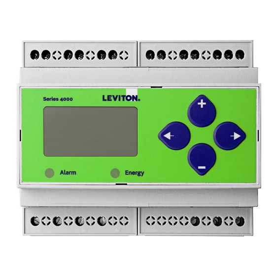
Series 4000-R
Compact Modbus Power and Energy Meter
For Use Only With U018 Series Rope Style CTs
Quick Install Guide
Z206884-0A
05145
U018 Series CT
(sold separately)
RoHS
Compliant
E50C2A
Additional Resources:
20497 SW Teton Avenue, Tualatin, OR 97062
1-503-404-5500
For a copy of the full installation
1-800-736-6682
guide for this product, visit
email: lescustomerservice@leviton.com
www.leviton.com.
www.leviton.com
Installation
WARNING: TO AVOID FIRE, SHOCK, OR DEATH, disconnect power prior to installation.
Reinstall any covers that are displaced during the installation before
powering the unit.
Mount the meter in an appropriate electrical enclosure near equipment to
be monitored.
Do not install on the load side of a Variable Frequency Drive (VFD).
The meter can be mounted in two ways: on standard 35 mm DIN rail or screw-mounted to the back of the
enclosure.
A. DIN Rail Mounting
1. Attach mounting clips to the underside
of the housing by sliding them into the
slots from the inside. The stopping pegs
must face the housing, and the outside
Insert clips from inside
edge of the clip must be flush with the
outside edge of the housing.
2. Snap the clips onto the DIN rail. See
diagram of the underside of the meter.
3. To prevent horizontal shifting across the
DIN rail, use two end stop clips.
Insert clips from outside
B. Screw Mounting
1. Attach the mounting clips to the underside
of the housing by sliding them into the slots
from the outside. The stopping pegs must
face the housing, and the screw hole must be
exposed on the outside of the housing.
2. Use three #8 screws (not supplied) to mount
the meter to the back of the enclosure. See
diagram of the underside of the meter.
Page 5
DANGER
HAZARD OF ELECTRIC SHOCK, EXPLOSION, OR ARC FLASH
• Turn off all power supplying equipment before working on or inside the equipment.
• Follow safe electrical work practices. See NFPA 70E in the USA, or applicable local codes.
• This equipment must only be installed and serviced by qualified electrical personnel.
• Read, understand and follow the instructions before installing this product.
• Product may use multiple voltage/power sources. Be sure all sources of power
have been disconnected before servicing.
• Use a properly rated voltage sensing device to confirm power is off.
DO NOT DEPEND ON THIS PRODUCT FOR VOLTAGE INDICATION
• Only install this product on insulated conductors.
Failure to follow these instructions will result in death or serious injury.
A quali ed person is one who has skills and knowledge related to the construction and
operation of this electrical equipment and the installation, and has received safety
training to recognize and avoid the hazards involved.
NEC2011 Article 100
No responsibility is assumed by Leviton for any consequences arising out of the use of
this material.
CAUTION
• This product is not intended for life or safety applications.
• Do not install this product in hazardous or classified locations.
• The installer is responsible for conformance to all applicable codes.
• Mount this product inside a suitable fire and electrical enclosure.
Provide a disconnect device to disconnect the meter from the supply source. Place this device in close
proximity to the equipment and within easy reach of the operator, and mark it as the disconnecting device.
The disconnecting device shall meet the relevant requirements of IEC 60947-1 and IEC 60947-3 and shall be
suitable for the application. In the US and Canada, disconnecting fuse holders can be used. Provide overcurrent
protection and disconecting device for supply conductors with approved current limiting devices suitable for
protecting the wiring. If the equipment is used in a manner not specified by the manufacturer, the protection
provided by the device may be impaired.
FCC PART 15 INFORMATION
NOTE: This equipment has been tested by the manufacturer and found to comply with the limits for a class B digital device,
pursuant to part 15 of the FCC Rules. These limits are designed to provide reasonable protection against harmful interfer-
ence when the equipment is operated in a residential environment. This equipment generates, uses, and can radiate radio
frequency energy and, if not installed and used in accordance with the instruction manual, may cause harmful interference
to radio communications. This device complies with part 15 of the FCC Rules. Operation is subject to the following two
conditions:
(1) This device may not cause harmful interference, and
(2) this device must accept any interference received, including interference that may cause undesired operation.
Modifications to this product without the express authorization of the manufacturer nullify this statement.
Page 2
Supported System Types
The meter has a number of different possible system wiring configurations (see Wiring Diagrams, page 9-10).
To configure the meter, set the System Type via the User Interface, Modbus register 130. The System Type
tells the meter which of its current and voltage inputs are valid, which are to be ignored, and if neutral is
connected. Setting the correct System Type prevents unwanted energy accumulation on unused inputs, selects
the formula to calculate the Theoretical Maximum System Power, and determines which phase loss algorithm
is to be used. The phase loss algorithm is configured as a percent of the Line-to-Line System Voltage (except
when in System Type 10) and also calculates the expected Line to Neutral voltages for system types that have
Neutral (12 & 40).
Values that are not valid in a particular System Type will display as "----" on the User Interface or as QNAN in
the Modbus registers.
CTs
Voltage Connections
System Type
Clip flush with
outside edge
Number
Qty
ID
Qty
ID
Type
Modbus Register
User
of
130
Interface:
Snap onto
SETUP>
wires
DIN rail
S SYS
Single-Phase Wiring
2
1
A
2
A,
L-N
10
1L + 1n
N
2
1
A
2
A, B
L-L
11
2L
3
2
A,
3
A,
L-L
12
2L + 1n
B
B,
with N
N
Three-Phase Wiring
3
3
A,
3
A,
Delta
31
3L
Screw holes
B,
B,
C
C
exposed for
mounting
4
3
A,
4
A,
Ground-
40
3L + 1n
B,
B,
ed Wye
C
C,
N
Page 6
For the complete safety
Specifications
information for this product,
see the full installation guide
Measurement Accuracy:
Real Power and Energy
at www.leviton.com
Input Voltage Characteristics:
Measured AC Voltage
For use in a Pollution Degree 2
Impedance
or better environment only. A
Frequency Range
Pollution Degree 2 environment
Input Current Characteristics:
must control conductive
Measurement Input Range
pollution and the possibility of
Control Power:
condensation or high humidity.
AC
Consider the enclosure, the
correct use of ventilation,
thermal properties of the
DC*
equipment, and the relationship
Ride Through Time
with the environment.
Mechanical Characteristics:
IP Degree of Protection (IEC 60529)
Installation category: CAT II or
Terminal Block Screw Torque
CAT III
Terminal Block Wire Size
Rail
Environmental Conditions:
Operating Temperature
Storage Temperature
Humidity Range
Altitude of Operation
Metering Category:
North America
CE
Dielectric Withstand
Conducted and Radiated Emissions
Conducted and Radiated Immunity
Compliance Information:
US and Canada (cULus)
Europe (CE)
* External DC current limiting is required, see fuse recommendations.
To avoid distortion, use parallel wires for control power and voltage inputs.
The following symbols are used in the wiring diagrams on the following pages.
Symbol
Voltage Disconnect Switch
Fuse (Installer is responsible for ensuring compliance with local requirements.
No fuses are included with the meter.)
Earth ground
Phase Loss
Wiring
Measurements
Diagram
VLL
VLN
Balance
Diagram
Current Transducer
number
X1
X2
Potential Transformer
AN
1
Protection containing a voltage disconnect switch with a fuse or disconnect
AB
2
circuit breaker. The protection device must be rated for the available short-
AB
AN,
AN-BN
3
circuit current at the connection point.
BN
NOTICE
AB,
AB-BC-CA
4
BC,
RISK OF EQUIPMENT DAMAGE
CA
• This product is designed only for use with U018 series current transducers (CTs).
AB,
AN,
AN-BN-
5, 6
• DO NOT USE CURRENT OUTPUT (e.g. 5A) CTs ON THIS PRODUCT.
BC,
BN,
CN & AB-
Failure to follow these instructions can result in equipment damage.
CA
CN
BC-CA
Dimensions
IEC 62053-22 Class 0.5S, ANSI C12.20 0.5%
Minimum 90V
(156V
) for stated accuracy;
L-N
L-L
UL Maximums: 600V
(347V
); CE Maximum: 300V
L-L
L-N
L-N
10.4 kΩ
45 to 65 Hz
U018 Series rope style CTs only
Bottom View (DIN Mount Configuration)
5VA max.; 90V min.
UL Maximums: 600V
(347V
)
L-L
L-N
CE Maximum: 300V
L-N
3W max.; UL and CE: 125 to 300VDC
100 msec at 120VAC
IP40 front display; IP20 Meter
3.6 "
(91 mm)
0.37 ft·lb (0.5 N·m) nominal/0.44 ft-lb (0.6 N·m) max.
24 to 14 AWG (0.2 to 2.1 mm
)
2
T35 (35 mm) DIN Rail per EN50022
0.2 "
-30° to 70°C (-22° to 158°F)
(4 mm)
-40° to 85°C (-40° to 185°F)
<95% RH (non-condensing)
3 km max.
Product Identification
CAT III; for distribution systems up to 347 V
/600VAC
L-N
L-L
CAT III; for distribution systems up to 300 V
L-N
Per UL 508, EN61010
Series 4000-R Unidirectional metering, Modbus full data set, pulse and alarm outputs. For use only with
FCC part 15 Class B, EN55011/EN61000 Class B
(residential and light industrial)
EN61000 Class A (heavy industrial)
UL508 (open type device)/CSA 22.2 No. 14-05
EN61010-1
Page 3
Product Diagram
Description
Two 5-character rows
of display text.
Top row alphanumeric;
Bottom row numeric only
The red alarm LED lights when
any of the 3 phase voltages drop
below the selected threshold:
The green Energy LED lights when
the energy pulse output contacts
Page 7
1.8"
(45mm)
1.9"
(48mm)
2.3"
(59mm)
1.5"
(39mm)
3.6"
4.2"
(91mm)
(107mm)
Bottom View (Screw Mount Configuration)
4.2 "
2.4 "
(61 mm)
(107 mm)
1.2 "
0.3 "
(31 mm)
+
+
(8 mm)
3.9"
(99 mm)
4.3 "
(109 mm)
0.4 "
+
(10 mm)
U018 Series CTs.
Page 4
X2 X1 X2 X1 X2 X1
A
B
C
Alarm
Energy
OUTPUT
(X2)
(X1) (X2)
(X1) (X2)
(X1)
NC
NO
+ - S
CT Inputs
U018 Series Only
+
–
Alarm
Energy
VOLTAGE INPUTS
CONTROL POWER
UL: 90V
- 600V
CE: 90V
- 300V
L-N
L-L
L-N
L-N
CAT III 50/60 Hz
0.1A 50/60 Hz
are closed.
A
B
C
N
1
2
Page 8
Advertisement

Related Manuals for Leviton 4000-R series


Summary of Contents for Leviton 4000-R series
- Page 1 (107 mm) correct use of ventilation, CE Maximum: 300V 1.2 “ No responsibility is assumed by Leviton for any consequences arising out of the use of 0.3 “ (31 mm) thermal properties of the 3W max.; UL and CE: 125 to 300VDC this material.
- Page 2 For more options (i.e., potential transformer ratios, etc.) and the full setup For all terminals on Series 4000 meters: Use 14-24 gauge wire instructions, see the full installation guide for the specific model at www.leviton.com. 0.37–0.44 ft•lb • When tightening terminals, apply the correct torque: (0.5–0.6 N•m)
Need help?
Do you have a question about the 4000-R series and is the answer not in the manual?
Questions and answers