Leviton 8000 Series Installation And User Manual
Hide thumbs
Also See for 8000 Series:
- User manual (38 pages) ,
- Installation manual (14 pages) ,
- Quick start manual (8 pages)

Subscribe to Our Youtube Channel
Related Manuals for Leviton 8000 Series


Summary of Contents for Leviton 8000 Series
- Page 1 Series 8000 Multi-Point High Density Meter Installation and User’s Manual Revision C PK-A3040-10-00-0A Dated May 5th, 2014 1.800.544.2843 www.calcert.com sales@calcert.com...
-
Page 2: Table Of Contents
9. Pulse Inputs ..........................30 10. Display Navigation ......................... 30 10.1 Normal Mode ........................30 10.2 Diagnostics Mode ......................30 11. CONFIGURATION TOOL CONFIGURATION....…………………………………...32 12. CONTACT INFORMATION ....................33 13. REGULATORY COMPLIANCE ..................36 Leviton Manufacturing Co., Inc. 1.800.544.2843 www.calcert.com sales@calcert.com... -
Page 3: Introduction
Ethernet ports for remote reporting Modbus serial port for remote reporting Serial port for remote display 2 pulse inputs to connect metering devices Table 1 lists the system specifications of the Series 8000 Leviton Manufacturing Co., Inc. 1.800.544.2843 www.calcert.com sales@calcert.com... - Page 4 Table 1: Series 8000 Meter System Specifications Specification Series 8000 Series 8000 Model: S8UTS/S8UWH Model: S8120 100mA Current Transformers* 100mA Current Transformers* For CT Part Numbers (see S8000 Data sheet) For CT Part Numbers (see S8000 Data sheet) Leviton Manufacturing Co., Inc. 1.800.544.2843 www.calcert.com sales@calcert.com...
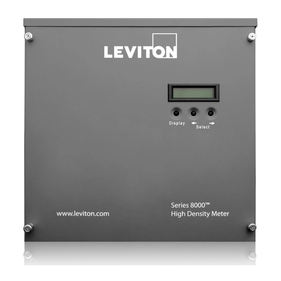
- Page 5 • Display button — cycles through the available information for each of the meter points • Left and right arrow buttons — selects which of the meter points is on the display Figure 1: Series 8000 front panel Leviton Manufacturing Co., Inc. 1.800.544.2843 www.calcert.com...
- Page 6 Figure 2 shows the internal view of the Series 8000 Figure 2: Series 8000 internal view (Meter Only) Leviton Manufacturing Co., Inc. 1.800.544.2843 www.calcert.com sales@calcert.com...
- Page 7 Figure 3 shows the dimensions of the Potential Transformer, Series 8000 Meter and CT Termination enclosure Figure 3: Product Dimensions Leviton Manufacturing Co., Inc. 1.800.544.2843 www.calcert.com sales@calcert.com...
- Page 8 Figure 4 shows the a functional Diagram of how all possible components fit together for a 3 phase 3 wire installation Figure 4: Product Wiring Diagram PT Enclosure (Optional)* Series 8000 CT Termination Enclosure 8000 Leviton Manufacturing Co., Inc. 1.800.544.2843 www.calcert.com sales@calcert.com...
-
Page 9: Safety Precautions
2. SAFETY PRECAUTIONS Carefully observe these safety instructions. Leviton Manufacturing Co., Inc. 1.800.544.2843 www.calcert.com sales@calcert.com... -
Page 10: Electrical Safety Compliance
RJ45 Ethernet patch cable o 4-wire 14 AWG (1.63 mm2) cable for three-phase wye connected circuits, or 3- wire 14 AWG (1.63 mm2) cable for a single-phase wye connected circuits mall flat-head screwdriver Leviton Manufacturing Co., Inc. 1.800.544.2843 www.calcert.com sales@calcert.com... - Page 11 3. “Installing the Sense Voltage and Control Voltage Cables in Wye and Delta Services” 4. “Installing the Current Transformers” 5. “Connecting the Ethernet Communications” 6. “Connecting the Modbus RTU Communications” 7. “Start-Up Sequence” 8. “Completing the installation record” Leviton Manufacturing Co., Inc. 1.800.544.2843 www.calcert.com sales@calcert.com...
- Page 12 4. Mount the shorting block enclosure on the wall as shown in Figures 3 and secure it by inserting a screw in each mounting keyhole and tightening the screws. In Figure 5, the meter is powered and takes its sense voltage directly from a breaker within the panel. Leviton Manufacturing Co., Inc. 1.800.544.2843 www.calcert.com sales@calcert.com...
- Page 13 Figure 5: 120V Mounting Layout, Dimensions and Clearances Leviton Manufacturing Co., Inc. 1.800.544.2843 www.calcert.com sales@calcert.com...
- Page 14 NOTE: Potential transformer burden depends on the control voltage source. If control voltage is provided separately (not derived from the metered voltage), t hen lower transformer burden may be acceptable. Contact your local Leviton representative for details. Potential transformers must be mounted in a listed electrical enclosure as shown in Figure 6.
- Page 15 In Figure 7, the meter is powered from the potential transformers that are fed from a breaker within the 347V/600V panel. The CT cable is connected to the shorting enclosure before connecting to the CTs in the panel. Figure 7: Typical 3-PH 347V installation Leviton Manufacturing Co., Inc. 1.800.544.2843 www.calcert.com sales@calcert.com...
- Page 16 The disconnect device must meet IEC 60947-1, IEC 60947-3 and/or comply with the local electrical code. Leviton Manufacturing Co., Inc. 1.800.544.2843 www.calcert.com...
- Page 17 NOTE: The phase wiring sequence A, B, C between the Series 8000 meter and the panel must match or the measurement readings will be wrong 4. If more than one meter is being installed, repeat this procedure for each additional meter. Leviton Manufacturing Co., Inc. 1.800.544.2843 www.calcert.com sales@calcert.com...
- Page 18 The Series 8000 meters are rated for direct input of 120V to 277V 60Hz phase potential. When metering services greater than 120V, the meter is powered from a separate 120V instrument transformer. Figure 8: Series 8000 meter in a 120/240V single-phase connection Leviton Manufacturing Co., Inc. 1.800.544.2843 www.calcert.com sales@calcert.com...
- Page 19 Install power supply shorting jumpers (see Figure 9) o For a 120/208V three-phase wye panel version with no shorting blocks (see Figure 10) Figure 9: S8000 meter 120/208V three-phase wye service connection Leviton Manufacturing Co., Inc. 1.800.544.2843 www.calcert.com sales@calcert.com...
- Page 20 Figure 10: For a 120/208V three-phase wye panel version with no shorting blocks Leviton Manufacturing Co., Inc. 1.800.544.2843 www.calcert.com sales@calcert.com...
- Page 21 Connect meter neutral terminal to neutral bar in the voltage disconnect panel (white wire) o Connect earth wire to earth post using lug provided o Install power supply shorting jumpers (see Figure 12) Figure 12: Series 8000 meter 240/416V three-phase wye service connection Leviton Manufacturing Co., Inc. 1.800.544.2843 www.calcert.com sales@calcert.com...
- Page 22 Connect earth wire to earth post using lug provided o From the auxiliary power transformer, connect 120V auxiliary power to AUXA and AUXN on the meter (see Figure 13) Figure 13: S8000 meter 277/480V three-phase wye service connection Leviton Manufacturing Co., Inc. 1.800.544.2843 www.calcert.com sales@calcert.com...
- Page 23 Connect the earth wire to earth post using lug provided o Check the 277V Input box on the UL label on the Series 8000 chassis (see figure Figure 14: 277/480V WYE wiring Leviton Manufacturing Co., Inc. 1.800.544.2843 www.calcert.com sales@calcert.com...
- Page 24 Check the 120V Input power box on the UL label on the Series 8000 chassis (see figure 15) Note: Refer to Installation Manual for the 120V wiring options of the Series 8000 to complete the install. Figure 15: 120 wiring conversion Leviton Manufacturing Co., Inc. 1.800.544.2843 www.calcert.com sales@calcert.com...
- Page 25 Install power supply shorting jumpers (see Figure 16) NOTE: For the wiring of the potential transformers, see Figure 4. Figure 16: Series 8000 meter 347/600V or higher three-phase wye service with potential transformers connection Leviton Manufacturing Co., Inc. 1.800.544.2843 www.calcert.com sales@calcert.com...
-
Page 26: Delta Service Metering
Connect meter neutral terminal to meter terminal B (black wire) o Connect earth wire to earth post using lug provided o Install power supply shorting jumpers (see Figure 17) Figure 17: Series 8000 meter 3PH Delta service connection Leviton Manufacturing Co., Inc. 1.800.544.2843 www.calcert.com sales@calcert.com... -
Page 27: Installing The Current Transformers
Series 8000 meter will be able to report using its factory default IP settings. If the local network is configured for static IP addresses, refer to the Series 8000 meter Configuration Guide for instructions on how to configure default static IP addresses. Leviton Manufacturing Co., Inc. 1.800.544.2843 www.calcert.com sales@calcert.com... -
Page 28: Connecting The Modbus Rtu Communications
2. Refer to the Series 8000 meter Configuration Guide for instructions on how to configure the baud rate, parity settings, and Modbus base address for the RS485 RTU communications. Figure 18: Modbus wiring diagram Leviton Manufacturing Co., Inc. 1.800.544.2843 www.calcert.com sales@calcert.com... -
Page 29: Start-Up Sequence
4. Power up the meter. The LCD on the front panel of the meter indicates the operating status of the unit as follows: a. Initial power up message “LEVITON” b. After the internal configuration is complete, the display shows default information for the first meter. -
Page 30: Pulse Inputs
In Diagnostics mode, pressing the Display button will scroll through the following additional information: Send data command CT Primary value and Real Power Watts per phase Voltage per phase Local IP address Leviton Manufacturing Co., Inc. 1.800.544.2843 www.calcert.com sales@calcert.com... - Page 31 PPP user name Phone number AT command string Alternate phone number Unit serial number Firmware build number Ethernet port MAC address Firmware revision Potential transformer ratio Leviton Manufacturing Co., Inc. 1.800.544.2843 www.calcert.com sales@calcert.com...
-
Page 32: Configuration Tool Configuration
Connect one or more S8000 meters to the same network, and the same subnet as the computer that will be running the S8000 Configuration Tool Start the Configuration Tool from the windows start menu or the shortcut on the desktop. Login as: UserName: Leviton Password: S8000 Leviton Manufacturing Co., Inc. 1.800.544.2843 www.calcert.com sales@calcert.com... -
Page 33: Contact Information
S8000 meters to connect to. After a few moments the meters found will be listed in a table. Select the S8000 to be programmed and click OK. Leviton Manufacturing Co., Inc. 1.800.544.2843 www.calcert.com... - Page 34 After a few moments the Configuration Tool will retrieve the existing programming from the meter and display the following screen. Leviton Manufacturing Co., Inc. 1.800.544.2843 www.calcert.com sales@calcert.com...
-
Page 35: Regulatory Compliance
Initial installation of the unit, and any subsequent modification to the unit, must be inspected by the local electrical safety authority. The Series 8000 meter complies with the standards listed in Table 3. Table 3: Regulatory Compliance Leviton Manufacturing Co., Inc. 1.800.544.2843 www.calcert.com sales@calcert.com...
Need help?
Do you have a question about the 8000 Series and is the answer not in the manual?
Questions and answers
Trying to change the default I.P. address to Series 8000 Leviton meter. Also, trying to locate the Configuration Guide.
To change the default IP address on a Leviton 8000 Series meter:
1. Power up the meter using the auxiliary power connector.
2. Connect the meter to the same network and subnet as the computer with the Leviton Configuration Tool installed.
3. Open the Configuration Tool on a Windows computer.
4. Log in with:
- Username: Leviton
- Password: S8000
5. Use the “Unit” drop-down to list and select the connected meter.
6. In the tool, locate the network settings where you can view and change the default IP address.
7. Update the IP address as needed and save the changes.
This process programs the network settings, including the default IP address, for the meter.
This answer is automatically generated