
Related Manuals for Leviton VerifEye


Summary of Contents for Leviton VerifEye
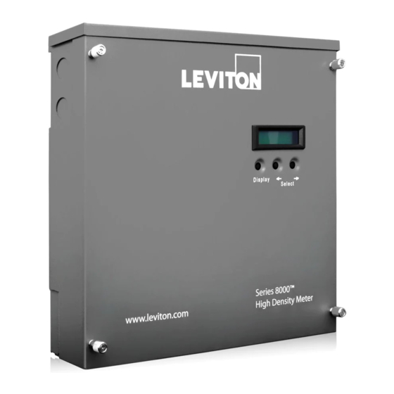
- Page 1 VerifEye™ Series 8000 Meter For use with catalog numbers: S8120, S8UWH & 277TS Quick Start Guide PK-A3236-10-00-0A...
-
Page 3: Table Of Contents
TABLE OF CONTENTS Warnings and Cautions ......................2 Important Notes ........................2 Section 1: Full system overview ................... 3 General Wiring Diagram: ....................... 3 Section 2: Voltage and Meter Power Wiring Reference ............4 Section 3: Wiring Diagrams ....................5 Split Phase 120/240 VAC (1P 3W) .................. -
Page 4: Warnings And Cautions
(not shown in the wiring diagrams). Failure to follow these instructions will result in death or serious injury. IMPORTANT NOTES • Please refer to the product manual or call/E-mail the Leviton Meter Support Team for further ®... -
Page 5: Section 1: Full System Overview
BROWN FROM SOURCE The system diagram is intended to show the various electrical connections required for the Leviton Series 8000 multi-circuit meter. Indicated in the diagram are the names of the specific components of the meter which will be referred to later in this guide. Follow the installation steps below for the appropriate wiring information depending on... -
Page 6: Section 2: Voltage And Meter Power Wiring Reference
SECTION 2: VOLTAGE AND METER POWER WIRING REFERENCE WARNING: Voltage references to the meter should be connected to a circuit breaker in the panel and/or with appropriate fusing based on the NEC and any local codes that are applicable. ® NOTE: 347/600 V and 480 V delta services require external PTs to step down the voltages before being wired to the meter. -
Page 7: Section 3: Wiring Diagrams
SECTION 3: WIRING DIAGRAMS 1-Phase 120 VAC (1P 2W) 1-Phase Wye 277 VAC (1P 2W) Black Brown White White Split Phase 120/240 VAC (1P 3W) Black White 3-Phase Wye 120/208 VAC (3P 4W) 3-Phase Wye 277/480 VAC (3P 4W) Yellow Blue Orange Black... -
Page 8: Section 4: Installing Current Transformers To Monitor The Loads
SECTION 4: INSTALLING CURRENT TRANSFORMERS TO MONITOR THE LOADS TO LOAD TO LOAD TO LOAD Correct installation of CT orientation on conductor from panel to load. This is an example of a three-phase installation. Use the appropriate diagram below to identify the correct orientation of the CT to the conductor. The “source” refers to the side facing incoming power from the utility. -
Page 9: Section 5: Installing The Ct Wire Harness & Connecting Ct Secondary Wires
Once the tenant spreadsheet has been filled out and completed, the last steps are to configure the meter through software and verify the hardware installation is correct. The manual includes the necessary information to complete the commissioning of the Leviton Series 8000 multi-circuit meter. -
Page 10: Ct Amperage Ratings And Tenant Information Chart
CT AMPERAGE RATINGS AND TENANT INFORMATION CHART Termination Module CT # 8106 - S8120-032 8112 - S8120-062 8118 - S8120-092 8124 - S8120-122, S8UWH-083, S8UWH-122, S8UWH-241... - Page 12 201 North Service Road, Melivlle, N.Y. 11747 Telephone: 1-800-323-8920 • FAX: 1-800-832-9538 Visit Leviton’s Web site at http://www.leviton.com © 2017 Leviton Manufacturing Co., Inc. All Rights Reserved Specifications and Price Subject to Change at any time without notice © 2018 Leviton Mfg. Co., Inc.
Need help?
Do you have a question about the VerifEye and is the answer not in the manual?
Questions and answers