Do you have a question about the 3CCD and is the answer not in the manual?
Questions and answers
Summary of Contents for Linvatec 3CCD
Page 1
The Linvatec 3CCD Digital Camera Instruction Manual (IM3300 - NTSC, IM3301 - PAL)
Page 2
Linvatec. Linvatec reserves the right to revise this publication and to make changes from time to time in the contents hereof without obligation to notify any person of such revision or changes, unless otherwise required by law.
3. Do not use camera with incompatible INTRODUCTION equipment or accessories that are not autho- rized by Linvatec. Doing so may void certi- t is recommended that personnel study this fications and/or warranties. manual before attempting to operate, clean, 4. Prior to each use, the controller and all...
Page 6
12. After each use, thoroughly clean unit and ference to other device(s) in the vicinity. accessories (See “3.1 Cleaning and Steril- However, there is no guarantee that interfer- izing” on page 22 ). ence will not occur in a particular installa- tion.
Type BF equipment. Camera Alternating Current. Single Use Only. No user service recommended. Refer servicing to qualified Linvatec service personnel. Protective Earth (ground). Warning - For continued pro- tection against risk of fire, replace only with same type and rating fuse.
The following 3CCD camera heads are compati- Receiving Inspection
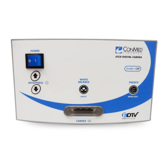
 ble with the IM3301 3CCD Digital Camera Controllers (PAL): Upon receipt, carefully unpack controller and • IM3325 Autoclavable Urology Camera accessories. Ensure all items listed below are Head included in the box and are free from damage. If •...
❶ ❷ ❺ ❸ ❹ This button is also used to select items System Indicators within the menus. ❹ “CAMERA” Receptacle — Insert the camera head connector here. The camera 1.5.1 Front Panel head connector and receptacle are specially ❶ keyed to prevent the camera head from “Power”...
❸ Y-Pb-Pr signal output. Connect to compati- Light Source Communication Connector ble equipment. Used to connect to a Linvatec LS6000 Light source. When connected, the camera and ❾ “DVI” Connector — Used for the digital light source work together to optimize the video signal output.
Connect the other end of the video cables to SYSTEM INSTALLATION the corresponding connectors (S-Video to and OPERATION S-Video, BNC to BNC or RGB to RGB) on the monitor and/or any other peripheral equipment. Utilizing the remote cable allows activation Installation of either a recorder or printer from the cam- era head buttons.
Page 12
Figure 2-2 SETUP - 2: Camera, printer and monitor system S-Video configuration MONITOR VIDEO - 1 VIDEO - 2 IM3300 CAMERA S-Video Cable PRINTER REMOTE 2 S-VIDEO S-Video Cable Remote Cable...
Page 13
Figure 2-3 SETUP - 3: Camera, printer and monitor system showing RGB configuration MONITOR VIDEO - 1 VIDEO - 2 IM3300 CAMERA PRINTER REMOTE 2 OUTPUT SYNC SYNC INPUT...
Page 14
Figure 2-4 SETUP - 4: Camera, Digital Documentation System (DDS) and monitor showing S-Video configuration MONITOR S-Video Cable VIDEO - 1 VIDEO - 2 REMOTE 1 IZZIT On Cable VP1500 DDS IM3300 CAMERA S-Video Cable Remote Cable...
Page 15
Figure 2-5 SETUP - 5: Camera, Digital Documentation System (DDS) and monitor showing RGB configuration MONITOR VIDEO - 1 VIDEO - 2 REMOTE 1 RGB to 15-pin Cable IZZIT On Cable IM3300 CAMERA VP1500 DDS RGB to 15-pin Cable Remote Cable...
Page 16
Figure 2-6: SETUP - 6: Camera, Digital Documentation System (DDS), VCR, Printer and monitor showing S-Video configuration MONITOR S-Video Cable VIDEO - 1 VIDEO - 2 REMOTE 1 IZZIT On Cable Remote Splitter Cable IM3300 CAMERA VP1500 DDS Remote Cable Remote Splitter Cable S-Video Cable S - VIDEO...
(d) Hold the scope tip steady and press the 2.1.1 Displaying Color Bars controller “White Balance” button or the camera head button (camera head Color bars test pattern allows the user to match button will only activate white balance the color between the camera controller and the if a “Push Camera Head Button”...
2.1.3 Adjusting Brightness 2.1.3.2 Using the Camera Head Buttons The brightness level can also be adjusted via the camera head buttons. In order to adjust the 2.1.3.1 Using the Camera Controller brightness level using the camera head buttons, the camera head button must be programmed 1.
(b) To zoom “in”, press camera head 2.1.4 Changing Presets button 1. The cursor will move to the right with each press until maximum The camera controller has different preset con- zoom is obtained. figurations designed to give the user the optimal image quality for different types of procedures (c) To zoom “out”, press camera head and different types of scopes.
2.1.6 Menu Operation 2.1.6.1 Options Menu There are several menus available to enable the The “Options Menu” allows access to the “Pre- user to customize the camera to best fit their sets Menu”, the “Button Menu”, and the auto needs. shutter on/off control.
(b) To turn the auto shutter off, select 2.1.6.2 Presets Menu “Shutter” from the “Options Menu”. “ON” should flash next to the word The “Presets Menu” allows users to customize “Shutter”. Press the down button. the Presets that can be accessed via the camera “OFF”...
(c) The window size defines what portion 2.1.6.3 Camera Head Button Menu of the image is utilized by the camera controller to determine the brightness level. Button 2 Button 1 • Small Window-determines the brightness based on the inner one-third portion of the image.
Page 23
2. Use the up and down buttons to scroll Attention: If the following screen appears, con- through the functions; printer and record for tact your Linvatec Representative. short button presses; brightness, zoom, or white balance for long button presses. White Balance Note: If the camera head button...
Camera Menu Reference Guide Menu Submenu/Function Option Option Menu • Presets Menu • Button Menu • Shutter Control • • Presets Menu • Preset 1 • Enhancement Control • Brightness Control • Window Size (small/large) • Gain (off, low, high) •...
Page 25
Head Button 1 Long Press • Brightness • Zoom • White Balance • Head Button 2 Short Press • Printer • Recorder • Head Button 2 Long Press • Brightness • Zoom • White Balance Service Menu (for Linvatec Sales Representative Only)
Linvatec recommends that the Turn the controller power off. Disconnect 3CCD Digital Camera be returned to the factory the power cord from the electrical power for routine maintenance every 24 months. Like- source and from the rear of the controller.
These cleaning instructions apply to the follow- ing camera heads only: 3.2.1 Disinfecting the Camera Heads • Autoclavable 3CCD Camera Heads These disinfecting instructions apply to the fol- (IM3320, IM3321, IM3322, IM3323, lowing camera heads only: IM3324, IM3325, IM3326) •...
Sterilization 3.3.1 Steam Sterilization of the Autoclavable 3CCD Camera Heads (IM3320, IM3321, IM3322, IM3323, IM3324, IM3325, IM3326) The recommended minimum sterilization exposure times are as follows: Table 1: Sterilization Parameters Minimum Sterilization Type Minimum Temperature Exposure Time Steam Pre-vacuum 270°F (132°C)
3.3.3 Other Processes The following Linvatec Autoclavable Camera Heads are material compatible with the STERRAD and STERIS processes. However, Linvatec has not conducted sterilization validation testing for the STERRAD and STERIS processes, and your institution is responsible for the normal sterility assurance validation.
If image is viewed, camera head and/or cable are faulty. Return camera head to Linvatec for repair. ♦ Camera head cable connector ♦ Insert camera head cable not inserted correctly or connector completely into the completely.
Page 31
Symptom Possible Cause Corrective Action ♦ Suspect camera head or cable. ♦ Flex camera cable. If picture is Intermittent picture. affected, return to factory for repair or replacement. ♦ Suspect video and/or power ♦ Flex video and power cables. If cables.
Page 32
Electronic Zoom” on page 15 for information on how to make appropriate selections). ♦ Faulty camera controller. ♦ Return faulty camera controller to Linvatec for repair. ♦ Too much light. ♦ Decrease camera controller’s Camera will not white balance. brightness.
Page 33
Symptom Possible Cause Corrective Action ♦ The camera controller’s “Menu ♦ Contact your local Linvatec “Menu Lock” appears when Lock” has been turned on. representative for information to “Presets” (menu/exit) unlock the menu. button is pressed and held. ♦ Video cables not connected ♦...
Fuse Replacement In the event of a blown fuse, a new one can be installed quickly and easily. 1. Ensure the power is off and the controller is unplugged from the power source. Using a small screwdriver or prying device, insert it into the slots of the fuse module until the fuse module is completely removed.
The signals now travel to the driver circuit TECHNICAL INFORMATION where they are encoded into S-Video and com- posite video. RGB video, S-video, and compos- ite video are driven to the back panel board. Theory of Operation Microcontroller Power Supply Microcontroller U24 is powered by the +5V The main power supply is a 50W switching supply which operates continuously when the...
Technical Specifications CAMERA CONTROLLER I.E.C. Equipment Classification: Type BF, Class 1, continuous operation when used with a Type BF Camera Head. Typical Operating Requirements: Input Voltage: 100 - 240 VAC Frequency: 50/60 Hz Power Consumption: 70 VA Fuse: T 1.0A, 250V Line Frequency Leakage: Chassis to Ground (120VAC): <...
Page 37
Ambient Temperature: -40° to 122°F (- 40°C to + 50°C) Relative Humidity: 10 to 90% non-condensing Atmospheric Pressure: 500 hPa to 1060 hPa Power Cord Requirements: 100/120 Volt (Linvatec Cat. No. C7104) Use only a listed (UL, CSA) detachable power cord manufactured to the following specifications. • Plug End •...
IM3323 Autoclavable 3CCD Urology Camera Head, “Cartridge” (NTSC format) IM3324 Autoclavable 3CCD Urology Camera Head, “Cartridge” (PAL format) IM3325 Autoclavable 3CCD Camera Head, IR Sensitive, “Eyecup” (NTSC format) IM3326 Drapes: Camera Drape 9” x 95” (10 per box) 9707 Camera Drape 5” x 96” (20 per box) 60-3950-031 Canister Drape 4.5”...
Page 39
Description Part Number BNC Video Cables: 6 ft. 8175-06 15 ft. 8175-15 20 ft. 8175-20 S-Video Cables: 1.5 ft. 8149-1.5 2 ft. 8149-3 6 ft. 8149-06 20 ft. 8149-20 25 ft. 8149-25 50 ft. 8149-50 75 ft. 8149-75 100 ft. 8149-100 “S”...
Page 40
Description Part Number Sterile Trays: Arthroscope Tray (holds 2 scopes) 7546 Autoclavable Arthroscope Tray (holds 2 scopes) C3106 Autoclavable Laparoscope Tray (holds 2 scopes) C3107 Autoclavable Tray for camera head, light guides and scopes C3108 Autoclavable Tray - two inner trays (holds multiple products) C3109 Hysteroscope Tray for soaking and storage (holds 2 scopes) 7562...
Need help?
Do you have a question about the 3CCD and is the answer not in the manual?
Questions and answers