
Related Manuals for enphase M175-24-240-S


Summary of Contents for enphase M175-24-240-S
- Page 1 Installation and Operations Manual Micro-Inverter M175-24-240-S Release 1.4 Page 1 Copyright Enphase Energy Inc. 2008 Release 1.4...
-
Page 2: Document Revision History
Phone: 707-763-4784 Toll Free: (877) 797-4743 Fax: 707-763-0784 www.enphaseenergy.com info@enphaseenergy.com Document Revision History Version Date Comments 01/16/08 Released 01/30/08 General edits 02/25/08 Final release edits 04/15/08 Updated Technical Data tables 06/16/08 Updated quick install guide Page 2 Copyright Enphase Energy Inc. 2008 Release 1.4... -
Page 3: Table Of Contents
Step 3 - Connecting the Enphase Micro-Inverter Wiring Harnesses ..7 Step 4 - System Grounding .............. 8 Step 5 - Enphase Installation Map and Connecting the PV Modules ..8 3 Commissioning ................9 4 Operating Instructions ..............10 5 Troubleshooting ................ -
Page 4: Important Safety Instructions
Connecting the Enphase Micro-Inverter to the electrical utility grid must only be done after receiving prior approval from the utility company. The body of the Enphase Micro-Inverter is the heat sink and can reach a temperature of 80!C. To reduce risk of burns, do not touch Do NOT disconnect the PV module from the Enphase Micro-Inverter without first removing AC power. -
Page 5: Introduction - The Enphase Micro-Inverter System
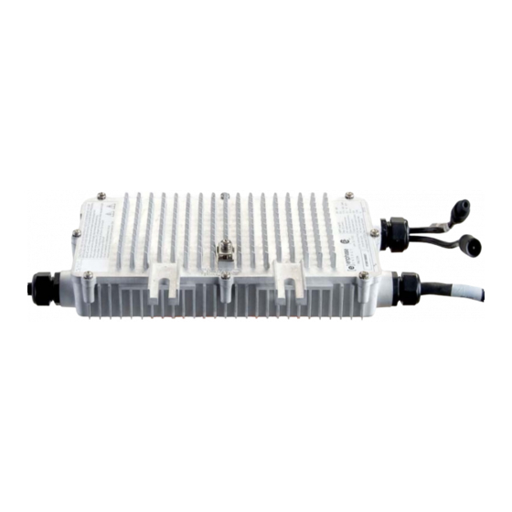
The distributed nature of the Micro-Inverter System insures that there is no single point of failure in the PV system. Enphase Micro-Inverters are designed to operate at full power at temperatures as high as 65!C (150!F). The inverter housing... -
Page 6: Installation Instructions
WARNING: Risk of electric shock. Normally grounded conductors may be ungrounded and energized when a ground fault is indicated. Installation of the Enphase Micro-Inverter System involves the following key steps: Installing the AC branch circuit junction box Attaching the Enphase Micro-Inverters to the racking... -
Page 7: Step 1 - Install The Ac Branch Circuit Junction Box
GEC. WARNING: Use electrical system components approved for wet locations only. NOTE: Please refer to the Enphase website for a list of approved PV module racking systems. NOTE: The Enphase M175-24-240-S Micro Inverter is designed to operate with most 72-cell PV module configurations;... -
Page 8: Step 4 - System Grounding
The Enphase Installation Map is designed to be a diagrammatic representation of the physical location of each Enphase Micro-Inverter in your PV installation. This information will be used by Enphase to provide you with detailed information about the performance of your PV system and graphically visualize your PV system on the Enphase Enlighten website. -
Page 9: Commissioning
Enphase will create a graphical representation of your PV system on the Enlighten website. The Enlighten web server will provide you with detailed information regarding the performance of your PV system (please go to www.enphaseenergy.com for more information on the... -
Page 10: Operating Instructions
Proper operation of the Enphase Micro-Inverters can be verified via the Emu. Troubleshooting Adhere to all the safety measures described throughout this manual. Enphase recommends the following troubleshooting steps in the event your PV system does not operate correctly: WARNING: The Enphase Micro-Inverter contains no user serviceable parts. -
Page 11: Troubleshooting Suggestions For Inoperable Micro-Inverters
Make sure that all the AC switches in the junction boxes are functioning properly and are closed. If the problem persists, please call customer support at Enphase Energy. Disconnecting the Enphase Micro-Inverter from the PV Module To insure the Micro-Inverter is not disconnected from the PV modules under load, adhere to the following procedure in the order shown: Turn off the AC disconnect on the AC branch circuit junction box. -
Page 12: Technical Data
Technical Data WARNING: It is required to match the DC operating voltage range of the PV module with the allowable input voltage range of the Enphase Micro-Inverter. WARNING: The maximum open circuit voltage of the PV module may not exceed the specified maximum input voltage of the Enphase Micro- Inverter. -
Page 13: Voltage And Frequency Limits For Utility Interaction
M175-24-240-S Micro-Inverter Operating Parameters Topic Unit Typical and duration AC Voltage trip limit accuracy "2.5 Frequency trip limit accuracy ±0.1 Trip time accuracy ±33 Miscellaneous Operating Parameters Maximum inverters per AC branch circuit Peak inverter efficiency 95.0 CEC weighted efficiency 94.5... -
Page 14: Appendix
Enphase repairs or replaces a Defective Product, the Limited Warranty continues on the repaired or replacement product for the remainder of the original Warranty Period or ninety (90) days from the date of Enphase’s return shipment of the repaired or replacement product, whichever is later. - Page 15 Inverters or costs related to the removal, installation, or troubleshooting of the customer's electrical systems. The Limited Warranty does not apply to, and Enphase will not be responsible for, any defect in or damage to any Enphase Micro-Inverter: (1) that has been misused, neglected, tampered with, altered, or otherwise damaged, either internally or externally;...
-
Page 16: Quick Installation Guide
Quick Installation Guide Page 16 Copyright Enphase Energy Inc. 2008 Release 1.4... -
Page 17: Enphase Installation Map
Enphase Installation Map Page 17 Copyright Enphase Energy Inc. 2008 Release 1.4...
Need help?
Do you have a question about the M175-24-240-S and is the answer not in the manual?
Questions and answers