enphase M250 Quick Install Manual
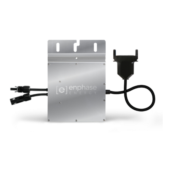
Microinverter
Hide thumbs
Also See for M250:
- Troubleshooting manual (45 pages) ,
- Installation and operation manual (42 pages) ,
- Quick install manual (4 pages)
Table of Contents
Advertisement
Quick Links
M 2 5 0 S A F E T Y
M250 (M250-60-2LL) Safety
Important Safety Information
This document contains important instructions to use during installation of the Enphase M250 Microinverter™. To reduce
the risk of electrical shock, and to ensure the safe installation and operation of the Enphase Microinverter, follow these in-
structions. The following safety symbols and information indicate dangerous conditions and important safety instructions.
Product Labels
WARNING: Hot surface.
DANGER: Risk of electrical shock.
Refer to product instructions.
Safety Instructions
DANGER: Before installing or using the Enphase Micro-
inverter, read all instructions and cautionary markings in
the technical description, on the Enphase Microinverter
System, and on the photovoltaic (PV) equipment.
DANGER: Do not use Enphase equipment in a manner
not specified by the manufacturer. Doing so may cause
death or injury to persons, or damage to equipment.
DANGER: Risk of Electrical Shock. Be aware that instal-
lation of this equipment includes risk of electric shock.
Do not install the AC junction box without first removing
AC power from the Enphase System.
DANGER: The Engage Cable terminator cap must not
be installed while power is connected.
DANGER: Electric shock hazard. The DC conductors
of this photovoltaic system are ungrounded and may be
energized.
WARNING: Always de-energize the AC branch circuit
before servicing. Never disconnect the DC connec-
tors under load. Disconnect DC connections first, then
disconnect AC connections.
WARNING: The body of the Enphase Microinverter is
the heat sink. Under normal operating conditions, the
temperature is 15°C above ambient, but under extreme
conditions the microinverter can reach a temperature of
80°C. To reduce risk of burns, use caution when work-
ing with microinverters.
⚠
WARNING: The M250 may be paired only with a 60-cell
PV module. The PV module DC conductors must be la-
beled "PV Wire" or "PV Cable" to be compliant with NEC
690.35(D) for Ungrounded PV Power Systems.
Safety and Advisory Symbols
DANGER! This indicates a hazardous situation, which if
not avoided, will result in death or serious injury.
⚠
WARNING! This indicates a situation where failure to
follow instructions may be a safety hazard or cause
equipment malfunction. Use extreme caution and follow
instructions carefully.
WARNING! This indicates a situation where failure to
follow instructions may result in burn injury.
✓
NOTE: This indicates information particularly impor-
tant for optimal system operation. Follow instructions
closely.
⚠
WARNING: If the AC cable on the microinverter is dam-
aged, do not install the unit.
⚠
WARNING: You must match the DC operating voltage
range of the PV module with the allowable input voltage
range of the Enphase Microinverter: 16-48V.
⚠
WARNING: The maximum open circuit voltage of the PV
module must not exceed the specified maximum input
voltage of the Enphase Microinverter: 48V DC.
⚠
WARNING: The M250 has field-adjustable voltage and
frequency trip points that you may need to set, depend-
ing upon local requirements. Only an authorized installer
with the permission and following requirements of the
local electrical authorities should make adjustments.
⚠
WARNING: Only use electrical system components ap-
proved for wet locations.
⚠
WARNING: Only qualified personnel should trouble-
shoot, install, or replace Enphase Microinverters or the
Engage Cable and Accessories.
⚠
WARNING: Make sure protective sealing caps have
been installed on all unused AC connectors. Unused AC
connectors are live when the system is energized by the
grid. Sealing caps may not be reused.
⚠
WARNING: Ensure that all AC and DC wiring is correct
and that none of the AC or DC wires are pinched or
damaged. Ensure that all AC junction boxes are properly
closed.
®
Advertisement
Table of Contents

Related Manuals for enphase M250


Summary of Contents for enphase M250
-
Page 1: Important Safety Information
M250 (M250-60-2LL) Safety Important Safety Information This document contains important instructions to use during installation of the Enphase M250 Microinverter™. To reduce the risk of electrical shock, and to ensure the safe installation and operation of the Enphase Microinverter, follow these in- structions. - Page 2 ✓ NOTE: The M250 works with 240 VAC single-phase util- to collect in the DC connector recess. Do not install the ity service or with 208 VAC three-phase utility service microinverter black side up or vertically, with the DC con- ✓...
- Page 4 Installing the M250 Microinverter (M250-60-2LL) NOTE: The M250 meets the requirements of NEC 690.35. Because the DC circuit is isolated and insulated from ground, the M250 does not require that you install a GEC between microinverters. To support this feature, the PV module must be equipped with DC cables labeled “PV Wire”...
- Page 5 Mark the approximate centers of each PV of NEC 690.35. Because the DC circuit is module on the PV racking. See notes in Step isolated and insulated from ground, the M250 Details on back. does not require a GEC. For further informa- tion, refer to: http://enphase.com/global/files/...
- Page 6 DC input connectors of their corre- with your hand or sponding microinverter. a wrench until the The status LED on the underside of each M250 latching mechanism lights green six seconds after DC power is meets the base–...
- Page 7 • Release the menu button when the LCD screen for both the branch circuit and all upstream conductors lead- displays Enable Device Scan. ing back to the PCC. See Circuit Calculations for M250 at http://www.enphase.com/support. b. Check that the LCD shows a complete device count after about 30 minutes.
Need help?
Do you have a question about the M250 and is the answer not in the manual?
Questions and answers