Table of Contents
Advertisement
Quick Links
Trademarks
®
®
Autel
, MaxiSys
, MaxiDAS
are trademarks of Autel Intelligent Technology Corp., Ltd., registered in China, the United
States and other countries. All other marks are trademarks or registered trademarks of their
respective holders.
Copyright Information
No part of this manual may be reproduced, stored in a retrieval system or transmitted, in
any form or by any means, electronic, mechanical, photocopying, recording, or otherwise
without the prior written permission of Autel.
Disclaimer of Warranties and Limitation of Liabilities
All information, specifications and illustrations in this manual are based on the latest
information available at the time of printing. Autel reserves the right to make changes at any
time without notice. While information of this manual has been carefully checked for
accuracy, no guarantee is given for the completeness and correctness of the contents,
including but not limited to the product specifications, functions, and illustrations.
Autel will not be liable for any direct damages or for any special, incidental, or indirect
damages or for any economic consequential damages (including the loss of profits).
IMPORTANT
Before operating or maintaining this unit, please read this manual carefully, paying extra
attention to the safety warnings and precautions.
For Services and Support:
pro.autel.com
www.autel.com
1-855-288-3587/1-855-AUTELUS (North America)
0086-755-86147779 (China)
support@autel.com
For technical assistance in all other markets, please refer to
this manual.
®
®
, MaxiScan
, MaxiTPMS
i
®
®
, MaxiRecorder
, and MaxiCheck
Technical Support
®
section in
Advertisement
Table of Contents

Subscribe to Our Youtube Channel
Related Manuals for Autel MaxiSys 906CV


Summary of Contents for Autel MaxiSys 906CV
- Page 1 All information, specifications and illustrations in this manual are based on the latest information available at the time of printing. Autel reserves the right to make changes at any time without notice. While information of this manual has been carefully checked for accuracy, no guarantee is given for the completeness and correctness of the contents, including but not limited to the product specifications, functions, and illustrations.
- Page 2 Safety Instructions The safety messages herein cover situations Autel is aware of. Autel cannot know, evaluate or advise you as to all of the possible hazards. You must be certain that any...
- Page 3 DANGER When an engine is operating, keep the service area WELL VENTILATED or attach a building exhaust removal system to the engine exhaust system. Engines produce carbon monoxide, an odorless, poisonous gas that causes slower reaction time and can lead to serious personal injury or loss of life. Do Not Turn the Volume Up Too Loud When Using Headphones Listening at high volumes that over-stimulate the ear for long periods of time may result in loss of hearing.
-
Page 4: Table Of Contents
CONTENTS 1 USING THIS MANUAL ....................1 ........................1 ONVENTIONS Bold Text ........................1 Note ..........................1 Important ........................1 Hyperlink ........................1 Procedures ......................... 1 2 GENERAL INTRODUCTION ..................3 MS906CV D ................3 ISPLAY ABLET Functional Description ....................3 Power Sources ...................... - Page 5 Manual VIN Input ...................... 21 Automatic Selection ....................22 Manual Selection ...................... 22 System Selection ...................... 23 ........................23 AVIGATION Diagnostics Screen Layout ..................23 Screen Messages ..................... 26 Making Selections ..................... 26 ........................27 IAGNOSIS ECU Information ....................... 30 Trouble Codes ......................
- Page 6 ........................63 PERATIONS Image Files ....................... 63 PDF Files ........................65 Review Data ......................66 Apps Uninstall ......................66 Data Logging ......................67 8 SETTINGS ........................68 ..........................68 ........................69 ANGUAGE ......................70 RINTING ETTING Printing via APP ......................70 Printing via PC ......................
- Page 7 12 ACADEMY ........................89 13 REMOTE DESK ......................90 14 QUICK LINK ......................... 92 15 MAXIFIX ........................93 ........................93 AVIGATION The Header ....................... 94 Select Vehicle Button ....................94 Terminology ......................94 ........................96 PERATIONS Home ........................96 Search Fix Features ....................96 Ask ..........................
-
Page 8: Using This Manual
Using This Manual This manual contains device usage instructions. Some illustrations shown in this manual may contain modules and optional equipment that are not included in your system. Contact your sales representative for availability of other modules and optional tools or accessories. Conventions The following conventions are used. - Page 9 To use the camera: Tap the Camera button. The camera screen opens. Focus the image to be captured in the view finder. Tap the blue circle. The view finder now shows the captured picture and auto-saves the taken photo.
-
Page 10: General Introduction
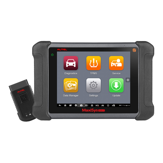
General Introduction ® The MaxiSys MS906CV is an advanced diagnostic device developed for customers looking for a tool with ultra-convenient and modern design while delivering ultimate performance. Featuring the powerful Samsung Exynos 5260 6-core processor (1.3 GHz quad-core ARM Cortex-A7 + 1.7 GHz dual-core ARM Cortex-A15), and an 8.0 inch LED capacitive touch screen, based on the Android multitasking operating system, and combined with the best possible coverage of OE-level diagnostics, the MaxiSys MS906CV is an ideal solution to manage your repair jobs smartly and conveniently with... - Page 11 The power LED displays different colors in response to the following scenarios: A. Green: Illuminates green when the Display Tablet is charging and the battery level is above 90%. Illuminates green when the Display Tablet is powered on and the battery level is above 15%.
-
Page 12: Power Sources
Figure 2-3 MaxiSys MS906CV Tablet Top View Mini SD Card Slot – holds the mini SD Card. Mini USB Port DC Power Supply Input Port – connects the 12 volt power adapter to charge. DB15-Pin Port – connects the vehicle DLC cable. Lock/Power Button –... - Page 13 Item Description Samsung Exynos 6-Core Processor (1.3 GHz Processor quad-core ARM Cortex-A7 + 1.7 GHz dual-core ARM Cortex-A15) Memory 2 GB RAM & 32 GB ROM 8.0 inch LED capacitive touch screen with Display 1024x768P resolution Wi-Fi (802.11 b/g/n) ...
-
Page 14: Accessories Kit
Accessories Kit Main Cable The Display Tablet can be powered through the Main Cable when connected to an OBD II/EOBD compliant vehicle. The Main Cable connects the Display Tablet to the vehicle’s data link connector (DLC). Figure 2-4 Main Cable – 1.7 m in length OBD I Adapters The OBD I adapters are for Non-OBD II vehicles. -
Page 15: Other Accessories
Other Accessories USB Cable Connects the Display Tablet to the PC. Mini USB Cable Connects the Display Tablet to the PC. AC/DC Adapter (12V) Connects the Display Tablet to the external DC power port for power supply. Cigarette Lighter Provides power to the Display Tablet or the J2534 programming device through connection to the vehicle’s cigarette lighter receptacle, as some non-OBD II vehicles cannot provide power via the DLC connection. -
Page 16: Getting Started
Getting Started Make sure the Display Tablet has sufficient battery level or is connected to the DC power supply (see Power Sources on page 5). Powering Up Press the Lock/Power button on the top right side of the Display Tablet to switch the unit on. -
Page 17: Application Buttons
NOTE The screen is locked by default when you first turn on the Display Tablet. It is recommended to lock the screen to protect the information in the system and reduce the power consumption. Almost all operations on the Display Tablet are controlled through the touch screen. The touch screen navigation is menu driven, which allows you to quickly locate the test procedure, or data that you need, through a series of choices and questions. -
Page 18: Locator And Navigation Buttons
Button Name Description Provides quick search for the supported Function functions and vehicles of Autel diagnostic Viewer tools. See Function Viewer on page 79. Launches Support platform which synchronizes Autel’s on-line service base Support station with the MaxiSys tablet. See Support on page 81. -
Page 19: System Status Icons
Button Name Description Android Returns to Android System’s Home screen. Home Displays a list of applications that are Recent Apps currently working. To open an app, touch it. To remove an app, swipe it to the right. Browser Launches the Android built-in browser. Opens the camera with short press;... -
Page 20: Powering Down
By tapping on the bottom right corner, a Shortcuts Panel will be displayed, on which you are allowed to adjust various system settings of the tablet. Operations of each button on the panel are described in the table below: NOTE The shortcuts buttons will be highlighted when enabled, and dimmed when disabled. -
Page 21: Reboot System
To install the printer driver program Insert the CD into the CD-ROM of the computer and open the CD folder. Double click on Autel Run.exe item. Click the MaxiSys Printer icon in the MaxiSys PC Suite screen. Select the installation language and the printer driver installation wizard will load momentarily. - Page 22 The MaxiSys Printer will print the received document automatically when the Auto Print option is selected. If you need to print the document later, click Open PDF file and select the document, and double click the Print button on the MaxiSys Printer interface to start the printing. NOTE Make sure the computer installed with the Printing driver program is connected to a printer.
-
Page 23: Cv Diagnostics
CV Diagnostics By establishing a data link to the electronic control systems of the vehicle being serviced directly, the CV Diagnostics application allows you to retrieve diagnostic information, view live data parameters, and perform active tests. The CV Diagnostics application can access the electronic control module (ECM) for various vehicle control systems, such as engine, transmission, antilock brake system (ABS), airbag system (SRS) and more. -
Page 24: Getting Started
Non-OBD II Vehicle Connection This type of connection requires both the main cable and a required OBD I adapter for the specific vehicle being serviced. To connect to a Non-OBD II Vehicle Connect the main cable’s female adapter to the Vehicle Data Connector on the Display Tablet, and tighten the captive screws. - Page 25 Figure 4-1 Sample Vehicle Menu Screen Top Toolbar Buttons Manufacturer Buttons Top toolbar Buttons The operations of the Toolbar buttons at the top of the screen are listed and described in the table below: Table 4-1 Top Toolbar Buttons Button Name Description Home...
-
Page 26: Vehicle Identification
Button Name Description Buses Displays the bus makes in the vehicle menu. Displays major automobile system Expert manufacturers. Opens the virtual keyboard, allowing you to Search manually enter the specific vehicle make required. Exits the search screen, or cancels an Cancel operation. -
Page 27: Auto Vin Scan
Auto VIN Scan The MaxiSys diagnostic system features the latest VIN-based Auto VIN Scan function to identify vehicles and scan all the diagnosable ECUs and run diagnostics on the selected system. This function is compatible with 2006 and newer vehicles. ... -
Page 28: Manual Vin Input
Tap Yes to confirm the vehicle profile or NO if the information is not correct. Figure 4-4 Sample Vehicle Information Screen The tool establishes communication with the vehicle and reads the control unit information. Choose Auto Scan to scan all the test vehicle available systems or tap Control Unit to access a specific system to diagnose. -
Page 29: Automatic Selection
Tap Done. Once the vehicle is identified, the Vehicle Diagnostics screen displays. Tap Cancel to exit Manual Input. Automatic Selection The Auto VIN Scan can be selected after selecting the test vehicle manufacturer. Figure 4-6 Sample Selection Screen To perform Automatic Selection Tap the Diagnostics application button from the MaxiSys Job Menu. -
Page 30: System Selection
System Selection This mode of vehicle selection allow you to select vehicle by the system and is also menu driven, repeat the first two steps from the automatic selection operation and tap System Selection. Through a series of on-screen prompts and selections, the test vehicle is chosen. - Page 31 Table 4-2 Diagnostics Toolbar Buttons Button Name Description Home Returns to the MaxiSys Job Menu. Touching this button allows you to exit the Vehicle diagnostic session of the currently identified test Swap vehicle, and returns you to the vehicle menu screen to select another vehicle for testing.
- Page 32 Button Name Description Tapping this button submits the Data Logging report Send to the technical center via the internet. To print data in Diagnostics Tap the Diagnostics application button from the MaxiSys Job Menu. The Print button on the diagnostic toolbar is available throughout the whole Diagnostics operations.
-
Page 33: Making Selections
Main Section The Main Section of the screen varies depending on the stage of operations. The Main Section can show vehicle identification selections, the main menu, test data, messages, instructions and other diagnostic information. Functional Buttons The displayed Functional Buttons at this section of the screen varies depending on the stage of operations. -
Page 34: Diagnosis
selection narrows the focus and leads to the desired test. Use your fingertip or the stylus pen to make menu selections. Diagnosis There are two options available when accessing the Diagnosis section: Auto scan – starts auto scanning for all the available systems on the vehicle. Control unit –... - Page 35 Navigation Bar Main Section Functional Buttons Navigation Bar List Tab – displays the scanned data in list format. Tree Tab – displays the scanned data in system distribution diagram format. Progress Bar – indicates the test progress. Main Section A.
- Page 36 Table 4-3 Functional Buttons in Auto Scan Name Description Back Returns to the previous screen or exit Auto Scan. Suspends scanning and changes to show the Continue Pause button. Confirms the test result, and continues to the system diagnosis after selecting the required system by tapping the item in the Main Section.
-
Page 37: Ecu Information
The Function Menu options vary slightly for different vehicles. The function menu may include: ECU Information – provides the retrieved ECU information in detail. Selecting opens an information screen. Trouble Codes – displays detailed information of DTC records retrieved from the ... -
Page 38: Trouble Codes
Diagnostics Toolbar Buttons – see Table 4-2 Diagnostics Toolbar Buttons page 24 for detailed descriptions of the operations for each button. Main Section – the left column displays the item names; the right column shows the specifications or descriptions. Functional Button – in this case, only a Back (or sometimes an ESC) button is available;... - Page 39 Freeze Frame – displays the critical parameter values at the time the DTC is set. Search – searches for the codes-related information online. Internet connection is required for this function. Clear DTC – erases the trouble codes. ESC –...
-
Page 40: Live Data
Live Data When this function is selected, the screen displays the data list for the selected module. The items available for any control module vary from one vehicle to another. The parameters display in the order that they are transmitted by the ECM, so expect variation between vehicles. - Page 41 There are 4 types of display modes available for data viewing, allowing you to view various types of parameters in the most suitable way. Tapping the drop-down button on the right side of the parameter name opens a submenu. There are 4 buttons to configure the data display mode, and one Help button on the right that you can tap for additional information.
- Page 42 screen. Tap the Edit Button, and an edit window appears. Select a parameter item on the left column. Select a desired sample color from the second column. Select a desired sample line thickness from the right column. Repeat step 4-7 to edit the waveform for each parameter item. Tap Done to save the setting and exit, or tap Cancel to exit without saving.
- Page 43 NOTE This mode supports Graph Merge for 2 to 3 parameter items only, so select no less than 2 or no more than 3 items each time when making graph merge. To cancel Graph Merge mode, tap the drop-down button on the right side of the parameter name, and select a data display mode.
- Page 44 Tap the Range navigation button. Select a parameter item on the left column, or enter the item name in the Search bar. Tap on the right side of the MIN button, and enter the required minimum value. Tap on the right side of the MAX button, and enter the required maximum value.
- Page 45 ○ Tap the > button on the right of Trigger Point bar and select a relative percentage of a record length to be reserved before the data recording start point. Tap Done to save the setting and return to the Live Data screen; or tap Cancel to cancel without saving and exit Setting.
-
Page 46: Service
Service The Service section is specially designed to provide you with quick access to the vehicle systems for various scheduled service and maintenance performances. The typical service operation screen is a series of menu driven executive commands. By following the on-screen instructions to select appropriate execution options, enter correct values or data, and perform necessary actions, the system will guide you through the complete performance for various service operations. -
Page 47: Oil Reset Service
Oil Reset Service This function allows you to perform reset for the Engine Oil Life system, which calculates an optimal oil life change interval depending on the vehicle driving conditions and climate. The Oil Life Reminder must be reset every time the oil is changed, so the system can calculate when the next oil change is required. -
Page 48: Electronic Parking Brake (Epb) Service
Figure 5-2 Sample Oil Reset Function List Follow the step-by-step on-screen instruction to complete the service. Take After treatment Maintenance as an example, it allows the technician to install and reset the after treatment system. Tap After treatment Maintenance on the Oil Reset function list to start the operation. -
Page 49: Epb Safety
Ensure that the EPB control system is reactivated after the maintenance work has been completed. NOTE Autel accepts no responsibility for any accident or injury arising from the maintenance of the Electronic Parking Brake system. To perform EPB functions Tap the Service application button from the MaxiSys Job Menu. - Page 50 Figure 5-4 Sample EPB Function List Follow the step-by-step on-screen instruction to complete the service. Take Parking brake cable replacement procedure as an example. Figure 5-5 Sample EPB Service Screen 1 Tap Start to carry out the service and the park brake cable position will change. Once the service is completed, the technician can replace the park brake cable.
-
Page 51: Steering Angle Sensor (Sas) Service
Accident repairs where damage to the steering angle sensor or assembly, or any part of the steering system may have occurred NOTE AUTEL accepts no responsibility for any accident or injury arising from servicing the SAS system. When interpreting DTCs retrieved from the vehicle, always follow the manufacturer’s recommendation for repair. -
Page 52: Calibrate Esc Steering Wheel Angle Sensor
Tap Special function to view the sub-function list. The list may vary by test vehicle. Figure 5-7 Sample SAS Function Menu Calibrate ESC Steering Wheel Angle Sensor This function allows users to perform steering angle sensor calibration and clear records. The function options vary with the vehicles being tested. -
Page 53: Dpf Service
When the operation is successfully finished, the scan tool will display a confirmation message. Otherwise, it will display a message to remind you of a problem. After you exit the diagnosis program, please repair the problem immediately. Figure 5-9 Sample SAS Function Screen 2 DPF Service The DPF function allows you to carry out numerous functions to the Diesel Particulate Filter system without having to send your car to a main dealer. -
Page 54: Dpf Deep Clean Regeneration
IMPORTANT Before diagnosing a problem vehicle and attempting to perform an emergency regeneration, it is important to obtain a full diagnostic log and read out relevant measured value blocks. NOTE The DPF will not regenerate if the engine management light is on, or there is a faulty EGR valve. -
Page 55: Cylinder Service
Figure 5-11 Sample DPF Service Screen 1 Tap OK to start the service. When the particulate filter is adequately cleaned, the test will stop and idle speed will return to normal. Once the service is completed, the tablet will display “Request is completed”. Please allow time for the engine and after treatment system to cool down. -
Page 56: Cylinder Cutout Test
Figure 5-13 Sample Cylinder Function List Screen Cylinder Cutout Test This test allow the technician to cutout cylinders for troubleshooting cylinder misfires. Tap Cylinder Cutout Test from the service function menu to enter the service screen. Figure 5-14 Sample Cylinder Service Screen 1... - Page 57 Tap the Cylinder you want to cutout to test. Figure 5-15 Sample Cylinder Service Screen 2 Once the cutout has been successfully carried out, the status will display Cutout. Figure 5-16 Sample Cylinder Service Screen 3 Tap Restore to restore the cylinders that have been cutout to ensure proper functioning.
-
Page 58: Turbo Service
Turbo Service If you think your vehicle might have a turbo-related problem, stop before you replace because turbo damage can often be a symptom of an underlying problem rather than the cause itself. The Turbo function helps a technician to troubleshoot the problem and facilitate accurate installation and calibration of an actuator. - Page 59 Tap Start to start the service and the status will display the message “Installation is running”. Figure 5-20 Sample Turbo Service Screen 2 The screen will display confirmation message once the actuator installation is successfully completed and the VGT actuator can be physically fitted on the turbo. Once the installation is mounted to the turbocharger, tap OK to proceed with the calibration.
-
Page 60: Injector Service
Figure 5-22 Sample Turbo Service Screen 4 The status will display “Actuator calibration is successfully completed”. Tap ESC to exit. Figure 5-23 Sample Turbo Service Screen 5 Injector Service The barcode printed on each injector must be programmed into the engine DCU every time one or more injectors are replaced. -
Page 61: High Pressure Common Rail Injector Setup
Figure 5-24 Sample Injector Service List Screen High Pressure Common Rail Injector Setup This function serves to monitor and change injector barcode in the ECM as necessary. The injector barcode is marked on the injector during manufacturing. Each time an injector is fitted or replaced, the injector barcode should be updated in the ECM. - Page 62 Tap Set barcode button to set the barcode for corresponding cylinder. Figure 5-26 Sample Turbo Service Screen 2 Tap Apply to set the barcode. Once the setup is successfully done, tap ESC to exit. Figure 5-27 Sample Turbo Service Screen 3...
-
Page 63: Shop Manager
Shop Manager The Shop Manager application manages the workshop information, customer information records, and test vehicle history records. There are three main functions available: Vehicle History Workshop Information Customer Manager The operations of these functions of the Shop Manager application are mainly manipulated by the toolbar buttons, which are listed and described in the table below: Table 6-1 Top Toolbar Buttons in Shop Manager Button... -
Page 64: Vehicle History
Vehicle History This function stores test vehicle history records, including vehicle information and the retrieved DTCs from previous diagnostic sessions. All information is displayed in summarized details. Tap on a record to resume a diagnostic session on a “stored vehicle”. Figure 6-1 Sample Vehicle History Screen ... -
Page 65: Historical Test Record
Historical Test Record The Historical Test record sheet is a detailed data form that includes general vehicle information such as vehicle year, make and model. The form also includes retrieved DTC from previous test and all information manually inputted by the technician. Figure 6-2 Sample Historical Test Record Sheet ... -
Page 66: Workshop Information
Workshop Information The Workshop Information form allows you to edit, input and save the detailed workshop information, such as shop name, address, phone number and other remarks, which when printing vehicle diagnostic reports and other associated test file, will display as the header of the printed documents. -
Page 67: History Notes
NOTE Required fields are noted. □ Tap the + photo frame beside the Name chart to add a photo. A sub menu displays, select Take Photo to take a new photo for the account, or select Choose Photo to choose from an existing image. Some customers may have more than one vehicle for service;... - Page 68 Select Customer Manager or Vehicle History. Select a customer account by tapping the corresponding name card. A Customer Information sheet displays (if Customer Manager is selected). Or, select a vehicle history record item to open the Historical Test record sheet (if Vehicle History is selected).
- Page 69 To add a note in History Notes Access History Notes. Tap the Add Notes button. An edit window displays. Tap on the Title bar to input a note title. Tap on the blank space below to edit a text note or remark. Select a function button on the top to add files in any form you choose.
-
Page 70: Data Manager
Data Manager The Data Manager application is used to store, print, and review the saved files. Most operations are controlled through the toolbar. Selecting the Data Manager application opens the file system menu. Different file types are sorted separately under different options, there are five types of information files to be viewed or played back. - Page 71 Figure 7-2 Sample Image Screen Toolbar Buttons – used to edit, print and delete the image files. See the following table for detailed information. Main Section – displays the stored images. Table 7-1 Toolbar Buttons in Image Screen Button Name Description Back Returns to the previous screen.
-
Page 72: Pdf Files
> Support & Updates > Firmware & Downloads > UPDATE CLIENT, and install to your windows-PC. The Maxi PC Suite consists of Autel Printer, MaxiSys Pinter and PC Suite. Double click on Setup.exe item. 10. Select the installation language and the printer driver installation wizard will load momentarily. -
Page 73: Review Data
The standard Adobe Reader application is used for file viewing and editing, please refer to the associated Adobe Reader manual for detailed instructions. Review Data The Review Data section allows playback of the recorded data frames of live data streams. On the Review Data main screen, select a record file to playback. -
Page 74: Data Logging
Data Logging The Data Logging section allows you to launch Support platform directly to view all records of all sent or unsent (saved) data loggings on the diagnostic system. For more details, please refer to Data Logging on page 85. -
Page 75: Settings
Settings Tap the Settings button to adjust the default setting and view information about the MaxiSys system. There are nine options available for the MaxiSys system settings: Unit Language Printing Setting Firmware Notification Center Multitask ... -
Page 76: Language
Figure 8-1 Sample Unit Setting Screen Language This option allows you to adjust the display language for the MaxiSys system. To adjust the language setting Tap the Settings application on the MaxiSys Job Menu. Tap the Language option on the left column. Figure 8-2 Sample Language Setting Screen Select the appropriate language. -
Page 77: Printing Setting
Printing Setting Configure this option to enable the tablet to print through a specified Wi-Fi network connection. To setup the printer connection Tap the Settings application on the MaxiSys Job Menu. Tap the Printing Setting option on the left column. Tap the Print via Network item to activate the printing function, which enables the device to send files to the printer through the networked PC via Wi-Fi connection. -
Page 78: Firmware
To install the printer driver program to a computer Download the Maxi PC Suite from www.autel.com and install to your windows-PC. Double click on Setup.exe item. Select the installation language and the wizard will load momentarily. Follow the instructions on the screen and click Next to continue. -
Page 79: Notification Center
Notification Center This option allows you to turn the Notification Center function on or off. The Notification Center function configures the MaxiSys tablet to receive regular on-line messages from the server for system update notifications or other service information via the Internet. It is highly recommended to keep this function ON all the time, to ensure notifications of updates are received. -
Page 80: Auto Update
on the MaxiSys system. Tap the Multi Task button, the Multi Task menu displays all active applications. To enable the Multitask function Tap Settings on the MaxiSys Job Menu. Tap Multitask on the left column. Tap ON/OFF to enable or disable the Multitask function. If the function is enabled the button displays blue, or if disabled the button displays gray. -
Page 81: System Settings
Figure 8-6 Sample Auto Update Screen Select the update type to schedule. Toggle the button to ON. – To set download time, use the button or tap on the numbers and the manual input screen will display. Tap Done to complete the time setting. Figure 8-7 Sample Set Time Screen NOTE The tool must be connected to the Internet at the time download is scheduled. -
Page 82: About
Tap the Settings application on the MaxiSys Job Menu. Tap the System settings option on the left column. Figure 8-8 Sample System Settings Screen Tap the App Switcher option on the left column. Check the box beside “Always show the App Switcher” on the right side of the screen, then the App Switcher icon will display. - Page 83 Figure 8-9 Sample About Screen...
-
Page 84: Update
Update The internal programming of the MaxiSys Diagnostic System, known as the firmware, can be updated using the Update application. Firmware updates increase the MaxiSys applications’ capabilities, typically by adding new tests, new models, or enhanced applications to the database. The display device automatically searches for available updates for all of the MaxiSys components when it is connected to the Internet. - Page 85 Main Section Left Column – displays vehicle logos and update firmware version information. Middle Column – displays a brief introduction about the new changes to the firmware operation or capabilities. Tap button to display an information screen to view more details, and tap the dim area around to close the window. Right Column –...
-
Page 86: Function Viewer
Function Viewer The Function Viewer allows you to search the functions supported by our tools and the software version information. There are two ways of searching, either by searching the tool and the vehicle or searching the functions. To search by the vehicle Tap the Function Viewer application on the MaxiSys Job Menu. - Page 87 Figure 10-2 Sample Function Viewer Screen 2 To search by the functions Tap the Function Viewer application on the MaxiSys Job Menu. The Function Viewer application screen displays. Tap the tool name on the top left to drop down the tool list, tap the one you want to search.
-
Page 88: Support
If you already have an Autel account, Sign In with your account ID and password. If you are a new member to Autel, click on the Create Autel ID button on the left side of the screen to create an ID. -
Page 89: Support Screen Layout
The User Info and Device Info are both included under the Personal Info section. User Info - displays detailed information of your registered on-line Autel account, such as your Autel ID, Name, Address and other contact information, etc. Device Info – displays the registered product information, including the Serial... -
Page 90: Update Info
Number, Registration Date, Expire Date, and Warranty Period. Update Info The Update Info section displays a detailed record list of the product’s software update history, including the product serial number, software version or name, and the update time. Service Info The Service Info section displays a detailed record list of the device’s service history information. - Page 91 Select the required processing time on the last section according to the urgency of the case. Tap Submit to send the completed form to Autel’s online service center, or tap Reset to refill it. The submitted complaints will be carefully read and handled by the service personnel, and the respond speed may depend on the processing time you’ve required.
-
Page 92: Data Logging
○ Select an existing complaint case item on the record list by tapping the > button on its right side. The screen displays the complaint session details. Tap the Post Reply button on the upper right side after viewing, to make a reply. -
Page 93: Communities
Communities The Communities section launches and synchronizes with the Technical Forums on Autel’s official website www.autel.com, where you are allowed to discuss technical topics or share information with, as well as ask for technical advices or offer technical supports to all other members in Autel’s online support communities. -
Page 94: User Profile
Training Channels The Training section provides quick links to Autel’s online video accounts. Select a video channel by the language to see all the available online tutorial videos from Autel for various technical supports, such as product usage techniques and vehicle... -
Page 95: Faq Database
FAQ Database The FAQ section provides you comprehensive references for questions frequently asked and answered about the use of Autel’s online member account, and shopping and payment procedures. Account – displays questions and answers about the use of Autel’s online user ... -
Page 96: Academy
Academy Autel provides various tutorial articles and technical bulletins produced by top-notch technicians and product experts. Please view the materials that are saved on the tablet or view technical articles from our online forum by clicking the links displayed under this application. -
Page 97: Remote Desk
You can use the application to receive ad-hoc remote support from Autel’s support center, colleagues, or friends, by allowing them to control your MaxiSys tablet on their PC via the TeamViewer software. - Page 98 remotely. Provide your ID to the partner, and wait for him/her to send you a remote control request. A popup displays to ask for your confirmation to allow remote control on your device. Tap Allow to accept, or tap Deny to reject. Refer to the associated TeamViewer documents for additional information.
-
Page 99: Quick Link
Quick Link The Quick Link application provides convenient access to Autel’s official website and to additional in automotive service sites. Figure 14-1 Sample Quick Link Screen To open a quick link Tap the Quick Link application on the MaxiSys Job Menu. The Quick Link application screen displays. -
Page 100: Maxifix
MaxiFix The MaxiFix application launches the on-line troubleshooter database, which not only provides you virtually all common diagnostic trouble code (DTC) database for most vehicles, but also serves as a forum allowing you to network with other MaxiSys users, and gives you access to a vast database of repair and diagnostic tips along with proven filed fixes. -
Page 101: The Header
accordance with the section selected on the Navigation Menu, allowing you to switch between functions. The Navigation Menu – the main menu at the bottom of the screen, which provides you access to different sections of MaxiFix. The Header The Header at the top of the screen features: ... - Page 102 filed into an all-in-one information source to provide you with quick and easy repair solutions. On MaxiFix community you can find Tips or share your own Tip with the community. To search for a MaxiFix Tip Select a Vehicle: Click Select Vehicle on the Header at the top of the page.
-
Page 103: Operations
Operations The Navigation Menu is at the bottom of the screen. Selecting the items on the Navigation Menu allows you to switch between the main sections on MaxiFix. These main sections include: Home – shows all questions and allows you to specify questions about one or ... -
Page 104: Ask
Questions – presents a list of open Question discussed in the community that may be pertinent to your search. Tips – presents a list of Tips that directly correlate to your search criteria. Select a Tip from the list to open and review the complete Tip. Real Fixes –... -
Page 105: My Maxifix
Marked Posts – opens a list with links to Tips and discussions that you are actively participating in. My Profile – allows you to view your Autel account information including: your Autel ID, personal information, MaxiFix score, phone number and register time, and edit your portrait. -
Page 106: My Messages
Use the Cancel button at the right-side bottom of the page to cancel your tip and return to the My MaxiFix page. Or use the Submit button at the right-side bottom of the page to contribute your tip to the community. Use the Attach File button at the left-side bottom of the page to include images or other supporting data with your question. -
Page 107: Support
Only one answer can be selected as “Adopted Answer”. Answers can only be rated by the MaxiFix member who asked the question. Close a Question When a repair question that you've posted to the community is resolved, you are encouraged to write down the case as a way to share a good solution. -
Page 108: Maintenance And Service
Maintenance and Service To ensure that the MaxiSys diagnostic tablet performs at its optimum level, we advise that the product maintenance instructions covered in this section is read and followed. Maintenance Instructions The following shows how to maintain your devices, together with precautions to take. ... -
Page 109: About Battery Usage
Your device may have not been connected to the charger properly. Check the connector. NOTE If the problems persist, please contact Autel’s technical support personnel or your local selling agent. About Battery Usage Your tablet is powered by a built-in Lithium-ion Polymer battery. This means that, unlike other forms of battery technology, you can recharge your battery while some charge remains without reducing your tablet’s autonomy due to the “battery memory effect”... -
Page 110: Service Procedures
This section introduces information for technical support, repair service, and application for replacement or optional parts. Technical Support If you have any question or problem on the operation of the product, please contact us. AUTEL NORTH AMERICA Phone: 855-AUTEL-US (855-288-3587) Monday-Friday 9am-6pm EST Website: www.autel.com Email: ussupport@autel.com... -
Page 111: Repair Service
For technical assistance in other markets, please contact your local selling agent. Repair Service If it becomes necessary to return your device for repair, please download the repair service form from www.autel.com, and fill in the form. The following information must be included: ... -
Page 112: Other Services
6th-10th Floor, Building B1, Zhiyuan, Xueyuan Road, Xili, Nanshan, Shenzhen, 518055, China Other Services You can purchase the optional accessories directly from Autel’s authorized tool suppliers, and/or your local distributor or agent. Your purchase order should include the following information: ... -
Page 113: Compliance Information
Compliance Information FCC Compliance FCC ID: WQ8MAXISYSMY906 This equipment has been tested and found to comply with the limits for a Class B digital device, pursuant to Part 15 of the FCC Rules. These limits are designed to provide reasonable protection against harmful interference in a residential installation. This equipment generates uses and can radiate radio frequency energy and, if not installed and used in accordance with the instructions, may cause harmful interference to radio communications. - Page 114 level of the device while operating can be well below the maximum value. This is because the device is designed to operate at multiple power levels so as to use only the power required to reach the network. To avoid the possibility of exceeding the FCC radio frequency exposure limits, human proximity to antenna should be minimized.
-
Page 115: Warranty
Warranty 12-Month Limited Warranty Autel Intelligent Technology Corp., Ltd. (the Company) warrants to the original retail purchaser of this MaxiSys Diagnostic Device that should this product or any part thereof during normal usage and under normal conditions be proven defective in material or...
Need help?
Do you have a question about the MaxiSys 906CV and is the answer not in the manual?
Questions and answers