Table of Contents
Advertisement
Advertisement
Table of Contents

Related Manuals for Autel MaxiSys Mini


Summary of Contents for Autel MaxiSys Mini
-
Page 2: Copyright Information
Autel will not be liable for any direct damages or for any special, incidental, or indirect damages or for any economic consequential damages (including lost profits). IMPORTANT: Before operating or maintaining this unit, please read this manual carefully, paying extra attention to the safety warnings and precautions. -
Page 3: Safety Information
Safety Instructions The safety messages herein cover situations Autel is aware of. Autel cannot know, evaluate or advise you as to all of the possible hazards. You must be certain that any condition or service procedure encountered do not jeopardize your personal safety. - Page 4 Safety Information Important Safety Instructions Do Not Turn the Volume Up Too Loud When Using Headphones Listening at high volumes that over-stimulate the ear for long periods of time may result in loss of hearing. SAFETY WARNINGS: Always perform automotive testing in a safe environment. ...
-
Page 5: Table Of Contents
Contents SAFETY INFORMATION ................... III CHAPTER 1 USING THIS MANUAL ..............1 ....................1 ONVENTIONS 1.1.1 Bold Text ....................1 1.1.2 Terminology .................... 1 1.1.3 Notes and Important Messages .............. 1 1.1.4 Hyperlinks ....................1 1.1.5 Procedures ....................2 CHAPTER 2 GENERAL INTRODUCTION ............... - Page 6 4.1.3 No Communication Message ..............20 ..................... 21 ETTING TARTED 4.2.1 Vehicle Menu Layout ................21 ..................23 EHICLE DENTIFICATION 4.3.1 Auto VIN Scan ..................23 4.3.2 Manual VIN Input .................. 24 4.3.3 Manual Vehicle Selection ..............25 4.3.4 Alternative Vehicle Identification ............28 .....................
- Page 7 6.2.4 Q&A ....................... 65 6.2.5 Support ....................65 CHAPTER 7 SETTINGS OPERATIONS ..............66 ..................... 66 PERATIONS 7.1.1 Unit ......................66 7.1.2 Language ....................66 7.1.3 Printing Setting ..................67 7.1.4 Push Message ..................67 7.1.5 About ..................... 68 7.1.6 System Settings ..................
- Page 8 15.2 ....................98 PERATIONS CHAPTER 16 MAINTENANCE AND SERVICE ............100 16.1 ................ 100 AINTENANCE NSTRUCTIONS 16.2 ............... 101 ROUBLESHOOTING HECKLIST 16.3 ................101 BOUT ATTERY SAGE 16.4 ................... 102 ERVICE ROCEDURES CHAPTER 17 COMPLIANCE INFORMATION ............104 CHAPTER 18 WARRANTY ..................105 viii...
-
Page 9: Chapter 1 Using This Manual
Using This Manual Chapter 1 This manual contains device usage instructions. Some illustrations shown in this manual may contain modules and optional equipment that are not included on your system. Contact your sales representative for availability of other modules and optional tools or accessories. Conventions The following conventions are used. -
Page 10: Procedures
Using This Manual Conventions 1.1.5 Procedures An arrow icon indicates a procedure. Example: To use the camera: Tap the Camera button. The camera screen opens. Focus the image to be captured in the view finder. Tap the blue circle. The view finder now shows the captured picture and auto-saves the taken photo. -
Page 11: Chapter 2 General Introduction
LED capacitive touch screen, and long-distance wireless communication, based on the multitasking mobile operating system, and combined with the best possible coverage of OE-level diagnostics, the MaxiSys Mini is the ideal solution to manage your repair jobs smartly and conveniently with greater mobility. - Page 12 General Introduction MaxiSys Display Tablet Figure 2-2 MaxiSys Tablet Back View Camera Flash Camera Lens Mini SD (secure digital) Card Slot - optional module Figure 2-3 MaxiSys Tablet Right Side Audio Speaker HDMI (high-definition multimedia interface) Port DC Power Supply Input Port...
-
Page 13: Power Sources
General Introduction MaxiSys Display Tablet Figure 2-4 MaxiSys Tablet Top View Lock/Power Button – turns the MaxiSys tool on and off with long press, or locks the screen with short press Volume Key USB Port Mini USB OTG Port Head Phone Jack 2.1.2 Power Sources The MaxiSys Display Tablet can receive power from any of the following sources:... -
Page 14: Technical Specifications
General Introduction MaxiSys Display Tablet 2.1.3 Technical Specifications Item Description Operating System Android 4.0, Ice Cream Sandwich Processor Samsung Exynos Quad-Core Processor 1.4GHz Memory 2GB RAM & 32GB On-board Memory Display 8.0 inch LED capacitive touch screen with 1024x768P resolution Connectivity Wi-Fi (802.11 a/b/g/n) ... -
Page 15: Vci - Bluetooth Diagnostic Interface
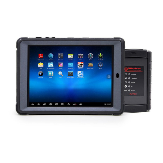
VCI – Bluetooth Diagnostic Interface General Introduction VCI – Bluetooth Diagnostic Interface 2.2.1 Functional Description Figure 2-5 Bluetooth Diagnostic Interface Vehicle Data Connector (DB15-Pin) Power LED - illuminates solid green when powered on Vehicle LED - flashes green when communicating with the vehicle’s network Error LED - illuminates solid red when serious hardware failure occurs;... -
Page 16: Technical Specifications
General Introduction Accessory Kit 2.2.2 Technical Specifications Item Description Communications Bluetooth V.2.1 + EDR USB 2.0 Wireless Frequency 2.4 GHz Input Voltage Range 12 VDC Supply Current 200 mA @ 12 VDC Operating Temperature 0° C to 50° C (ambient) Storage Temperature -20°... -
Page 17: Obd I Adapters
General Introduction Accessory Kit 2.3.2 OBD I Adapters The OBD I adapters are for Non-OBD II vehicles. The adapter used depends on the type of vehicle make being tested. The most common adapters are shown below. Benz-14 Chrysler-16 BMW-20 Kia-20 Fiat-3 Honda-3 GM/Daewoo-12... - Page 18 General Introduction Accessory Kit AC/DC External Power Adapter Connects the display tablet to the external DC power port for power supply. Compact Disc (CD) Includes the User Manual, Printing Services Program and Update Application, etc. Cigarette Lighter Provides power to the display tablet through connection to the vehicle’s cigarette lighter receptacle, as some non-OBD II vehicles cannot provide power via the DLC connection.
-
Page 19: Chapter 3 Getting Started
Getting Started Chapter 3 Make sure the MaxiSys Display Tablet has a charged battery or is connected to the DC power supply (see 2.1.2 Power Sources on page 5). Powering Up Press the Lock/Power button on the top left side of the display tablet to switch the unit on. -
Page 20: Application Buttons
Configures your unit to receive remote support Remote using the TeamViewer application program. See Desk Remote Desk Operations on page 81. Launches Support platform which synchronizes Autel’s on-line service base station Support with the MaxiSys tablet. See Support Operations on page 83. -
Page 21: Locator And Navigation Buttons
Getting Started Powering Up Name Button Description Allows you to store and play technical tutorial and training videos about the device usage or vehicle Training diagnostic techniques. See Training Operations on page 92. Provides associated website bookmarks to allow quick access to product update, service, support Quick Link and other information. -
Page 22: System Status Icons
Getting Started Powering Down Name Button Description Opens the VCI Manager application. The tick icon at the bottom right corner indicates the display tablet is communicating with the VCI device, otherwise a cross icon displays. MaxiSys Returns to the MaxiSys operation interface Shortcut from other Android applications. -
Page 23: Reboot System
Getting Started Install Computer Software 3.2.1 Reboot System In case of system crash, press and hold the Lock/Power button for 8 seconds to reboot the system. Installing Computer Software The MaxiSys Diagnostic Platform allows you to realize some of its functions on a computer to enhance capabilities and improve user experience. - Page 24 Getting Started Install Computer Software Make sure the display tablet is connected to the computer network, either via Wi-Fi or LAN, before printing. See 7.1.3 Printing Setting page 67 for more information. Run the Printing Services program on the computer. Tap the Print button on the toolbar displayed in various applications of the MaxiSys system.
-
Page 25: Chapter 4 Diagnostics Operations
When these are done, check the VCI navigation button at the bottom bar on the screen, if the button displays a green tick icon at the lower right corner, the MaxiSys Mini diagnostic platform is ready to start vehicle diagnosis. - Page 26 Diagnostics Operations Establishing Vehicle Communication OBD II Vehicle Connection This type of connection only requires the main cable without any additional adapter. To connect to an OBD II vehicle Connect the main cable’s female adapter to the Vehicle Data Connector on the VCI device, and tighten the captive screws.
-
Page 27: Vci Connection
Diagnostics Operations Establishing Vehicle Communication 4.1.2 VCI Connection After the VCI device is properly connected to the vehicle, the Power LED on the VCI device illuminates solid green light, and is ready to establish communication with the MaxiSys display tablet. The Bluetooth Diagnostic Interface supports 2 communication methods with the MaxiSys display tablet: Bluetooth and USB. -
Page 28: No Communication Message
Diagnostics Operations Establishing Vehicle Communication When paring is successfully done, the connection status displayed to the right of the device name is shown as Paired. Wait for a few seconds, and the VCI button on the system Navigation bar at the bottom of the screen shall display a green tick icon, indicating the display tablet is connected to the VCI device, and is ready to perform vehicle diagnosis. -
Page 29: Getting Started
Diagnostics Operations Getting Started In case of wired connection, check the cable connection between the display tablet and the VCI device. Check if the green LED on the VCI device is illuminated for Bluetooth or USB. Check if the Error LED on the VCI device is on, this may indicate there is a communication error between the devices, in this case try re-establishing the connection again;... - Page 30 Diagnostics Operations Getting Started the Diagnostics application button on the MaxiSys Job Menu, the screen then opens the Vehicle Menu. Figure 4-1 Sample Vehicle Menu Screen Top Toolbar Buttons Manufacturer Buttons Top toolbar Buttons The operations of the Toolbar buttons at the top of the screen are listed and described in the table below: Table 4-1 Top Toolbar Buttons Name...
-
Page 31: Vehicle Identification
Diagnostics Operations Vehicle Identification Name Button Description Europe Displays the European vehicle menu. Asia Displays the Asian vehicle menu. Domestic Displays the Domestic vehicle menu. Touching this button opens the virtual keyboard, Search allowing you to manually enter the specific vehicle make required. -
Page 32: Manual Vin Input
Diagnostics Operations Vehicle Identification To perform Auto VIN Scan Tap the Diagnostics application button from the MaxiSys Job Menu. The Vehicle Menu displays. (Figure 4-1) Tap the VIN Scan button on the top toolbar. Select Auto Detect. The tester starts VIN scanning on the vehicle’s ECU. -
Page 33: Manual Vehicle Selection
Diagnostics Operations Vehicle Identification Figure 4-3 Manual VIN Input Tap Done. The vehicle will be identified in a few seconds, and once the matching is successful, the system will guide you to the Vehicle Diagnostics screen directly. (Figure 4-2) Tap Cancel to exit Manual Input. 4.3.3 Manual Vehicle Selection When the vehicle’s VIN is not automatically retrievable through the vehicle's ECU, or the specific VIN is unknown, you can choose to select the vehicle... - Page 34 Diagnostics Operations Vehicle Identification B. Manual Vehicle Entry This mode allows you to manually enter and save specific vehicle information, such as PCM Part Number, Vehicle Calibration Number, or Tear Tag. This function enables direct access to the vehicle's ECM and saves your time of doing step-by-step entry selections.
- Page 35 Diagnostics Operations Vehicle Identification Figure 4-5 PCM Part Number Input Screen Tap OK to continue when the input is done. A confirming screen showing the Vehicle Information displays. Check if the vehicle information is correct, and then from the confirming screen, select: Yes to continue.
-
Page 36: Alternative Vehicle Identification
Diagnostics Operations Navigation Check if the vehicle information is correct, and then from the confirming screen, select: Yes to continue. No to return to the vehicle selection menu. Select Yes and the Vehicle Diagnostics screen displays. (Figure 4-2) 4.3.4 Alternative Vehicle Identification Occasionally, you may identify a test vehicle that the tester does not recognize;... - Page 37 Diagnostics Operations Navigation Diagnostics Toolbar Status Information Bar Main Section Functional Buttons Diagnostics Toolbar The Diagnostics toolbar contains a number of buttons that allow you to print or save the displayed data and make other controls. The table below provides a brief description for the operations of the Diagnostics toolbar buttons: Table 4-2 Diagnostics Toolbar Buttons Name...
-
Page 38: Main Section
Diagnostics Operations Navigation Name Button Description Records the communication data and Data information of the test vehicle. The saved data can Logging be reported and sent to the technical center via the internet. (Coming soon) To perform data printing in Diagnostics Tap the Diagnostics application button from the MaxiSys Job Menu. -
Page 39: Screen Messages
Diagnostics Operations Navigation Functional Buttons The displayed Functional Buttons at this section of the screen varies depending on the stage of operations. They can be used to navigate, save or clear the diagnostic data, exit scanning as well as make other functional controls. -
Page 40: Main Menu
NOTE: The accompanied Bluetooth Diagnostic Interface does not support the ECU programming function. Autel’s J2534 ECU programming device is the ideal device to perform this function, which is available for your choice. After a section is selected and the tablet establishes communication with the vehicle via the VCI device, the corresponding function menu or selection menu displays. - Page 41 Diagnostics Operations Diagnosis Figure 4-7 Sample Auto Scan Operation Screen Navigation Bar Main Section Functional Buttons Navigation Bar List Tab – displays the scanned data in list format Tree Tab – display the scanned data in system distribution diagram format Progress Bar –...
- Page 42 Diagnostics Operations Diagnosis -?-: Indicates that the vehicle control system has been detected, but the tester cannot accurately locate it. Indicates there is/are detected fault code(s) present; “#” Fault | #: indicates the number of the detected faults. Pass | No Fault: Indicates the system has passed the scanning process and no fault has been detected.
- Page 43 Diagnostics Operations Diagnosis Control Units This option allows you to manually locate a required control system for testing through a series of choices. You simply follow the menu driven procedure, and make proper selection each time; the program will guides you to the diagnostic function menu after a few choices you’ve made.
-
Page 44: Ecu Information
Diagnostics Operations Diagnosis Special Functions – provides component adaptation or variant coding functions for custom configurations, and also allows you to reprogram adaptive values for certain components after making repairs. Depending on the test vehicle, this selection may sometimes appear as Control Unit Adaptations, Special Functions, Variant Coding, Configuration or something similar. -
Page 45: Read Codes
Diagnostics Operations Diagnosis Diagnostics Toolbar Buttons – see Table 4-2 Diagnostics Toolbar Buttons on page 29 for detailed descriptions of the operations for each button. Main Section – the left column displays the item names; the right column shows the specifications or descriptions. Functional Button –... -
Page 46: Erase Codes
Diagnostics Operations Diagnosis Status Column – indicates the status of the retrieved codes. Description Column – detailed descriptions for the retrieved codes. Snowflake Icon – only displays when freeze frame data is available for viewing; Selecting displays a data screen, which looks very similar to the Read Codes interface, therefore same operation method may be applied. - Page 47 Diagnostics Operations Diagnosis Gesture scrolling allows you to quickly move through the data list. Simply touch the screen and drag your finger up or down to reposition the parameters being displayed if the data covers more than one screen. The figure below shows a typical Live Data screen: Figure 4-11 Sample Live Data Screen Diagnostics Toolbar Buttons –...
- Page 48 Diagnostics Operations Diagnosis To change the unit mode, tap the Setting button on the top toolbar and select a required mode. See 7.1.1 Unit on page 66 for more information. Display Mode There are 4 types of display modes available for data viewing, allowing you to view various types of parameters in the most suitable way for better data check-ups.
- Page 49 Diagnostics Operations Diagnosis Edit Button – tapping this button opens an edit window, on which you can set the waveform color and the line thickness displayed for the selected parameter item. Scale Button - changes the scale values, which are displayed below the waveform graph.
- Page 50 Diagnostics Operations Diagnosis Flag – this button appears when the Record function is applied. Tapping this button sets flags for the recorded data at points wherever you choose, when playing back the recorded video clip later in Data Manager, the preset flag will enable a popup to allow input of text to take notes.
- Page 51 Diagnostics Operations Diagnosis There are four navigation buttons on top of the Setting mode screen. Range Button – displays the configuration screen on which you can set the threshold values, an upper limit and a lower limit, for triggering the buzzer alarm.
- Page 52 Diagnostics Operations Diagnosis Trigger Type – sets the trigger mode for data recording, mainly of two kinds: Manual and Auto. There are four options available: Manual – allows you to manually start and stop data recording DTC – auto triggers data recording when any DTC is detected DTC Check Mode –...
-
Page 53: Active Test
Diagnostics Operations Diagnosis 4.6.5 Active Test The Active Test function is used to access vehicle-specific subsystem and component tests. Available test vary by manufacturer, year, and model, and only the available tests display in the menu. During an active test, the tester outputs commands to the ECU in order to drive the actuators. -
Page 54: Special Functions
Diagnostics Operations Diagnosis 4.6.6 Special Functions These functions perform various component adaptations, allowing you to recalibrate or configure certain components after making repairs or replacement. The main section of the Adaptation Operation screen displays a list of operational and vehicle status information, which mainly consists of four parts: The first part in the top line shows the description of the operation being performed, and the execution status is displayed on the right, such as Completed, or Activated, etc. -
Page 55: Service
Diagnostics Operations Service Read the information carefully and check the vehicle condition accordingly, when you are sure that the vehicle is ready to perform the adaptation, simply follow the instruction provided to make appropriate selections. When the operation is done, an execution status message such as Completed, Finished or Successful, displays. -
Page 56: Generic Obd Ii Operations
Diagnostics Operations Generic OBD II Operations Electric Parking Brake (EPB) Service This function has a multitude of usages to maintain the electronic braking system safely and effectively. The applications include deactivating and activating the brake control system, assisting with brake fluid control, opening and closing brake pads, and setting brakes after disc or pad replacement, etc. -
Page 57: General Procedure
Diagnostics Operations Generic OBD II Operations 4.8.1 General Procedure To access the OBD II/EOBD diagnostics functions Tap the Diagnostics application button from the MaxiSys Job Menu. The Vehicle Menu displays. Tap the EOBD button. There are two options to establish communication with the vehicle. -
Page 58: Function Descriptions
Diagnostics Operations Generic OBD II Operations Select a function option to continue. DTC & FFD I/M Readiness Live Data O2 Sensor Monitor On-Board Monitor Component Test Vehicle Information Vehicle Status NOTE: Some functions are supported only on certain vehicle makes. 4.8.2 Function Descriptions This section describes the various functions of each diagnostic option: DTC &... - Page 59 Diagnostics Operations Generic OBD II Operations Stored Codes Stored codes are the current emission related DTCs from the ECM of the vehicle. OBD II/EOBD Codes have a priority according to their emission severity, with higher priority codes overwriting lower priority codes. The priority of the code determines the illumination of the MIL and the codes erase procedure.
- Page 60 Diagnostics Operations Generic OBD II Operations I/M Readiness This function is used to check the readiness of the monitoring system. It is an excellent function to use prior to having a vehicle inspected for compliance to a state emissions program. Selecting I/M Readiness opens a submenu with two choices: Since DTCs Cleared –...
-
Page 61: Exiting Diagnostics
Diagnostics Operations Exiting Diagnostics Vehicle Information The option displays the vehicle identification number (VIN), the calibration identification, and the calibration verification number (CVN), and other information of the test vehicle. Vehicle Status This item is used to check the current condition of the vehicle, including communication protocols of OBD II modules, retrieved codes amount, status of the Malfunction Indicator Light (MIL), and other additional information may be displayed. -
Page 62: Chapter 5 Data Manager Operations
Data Manager Operations Chapter 5 The Data Manager application is used to store, print, and review the saved files. Most operations are controlled through the toolbar. Selecting the Data Manager application opens the file system menu. Different file types are sorted separately under different options, there are six types of information files to be viewed or played back. - Page 63 Data Manager Operations Operations Figure 5-2 Sample Image Database Screen Toolbar Buttons – used to edit, print and delete the image files. See Table 5-1 Toolbar Buttons in JPG Database on page 55 for detailed information. Main Section – displays the stored images. Table 5-1 Toolbar Buttons in JPG Database Name Button...
-
Page 64: Pdf Files
Data Manager Operations Operations To edit image information Select Data Manager application from the MaxiSys Job Menu. Select Image to access the JPG database. Select an image to display it in full screen. Tapping the screen once displays the editing toolbar. Tap the Info button to open a window displaying the image information. -
Page 65: Review Data
Data Manager Operations Operations 5.1.3 Review Data The Review Data section allows you to playback the recorded data frames of live data streams. On the Review Data main screen, select a record file to playback. Figure 5-3 Sample Data Playback Screen Drop-down Toolbar –... -
Page 66: Chapter 6 Maxifix Operations
MaxiFix Operations Chapter 6 The MaxiFix application launches the on-line troubleshooter database, which not only provides you virtually all common diagnostic trouble code (DTC) database for most vehicles, but also serves as a forum allowing you to network with other MaxiSys users, and gives you access to a vast database of repair and diagnostic tips along with proven filed fixes. - Page 67 MaxiFix Operations Navigation The MaxiFix interface has 3 main areas: Header Bar – located across the top of the page, is used to select vehicles and perform keyword searches. Navigation Bar – located along the left-hand side of the page is used to access the main features of MaxiFix.
-
Page 68: Terminology
On MaxiFix you can search for Tips or enter your own Tip to help other community members resolve vehicle issues. MaxiFix Tips consist of 3 types of Tips: Autel Certified Tips – these tips have gone through rigorous review by experts. Real Fix Tips – these tips are gathered from actual shop repair orders and are presented in an easy to understand Complaint, Cause, Correction format. -
Page 69: Operations
MaxiFix Operations Operations Operations The Navigation Bar is on the left side of the screen. Buttons on the Navigation Bar launch the main sections of MaxiFix. Available Navigation Bar selections include: Home – shows the recently viewed questions and fixes, along with the ... -
Page 70: Your Cloud
MaxiFix Operations Operations Points System 1 point is awarded for answering a question. 5 points are awarded if your answer is rated as “Good Answer” by the MaxiFix community member who asked the question. 10 points are awarded if your answer is rated as the “Best Answer” by ... - Page 71 MaxiFix Operations Operations Symptoms – this is where you describe how the vehicle is behaving. Diagnostics Steps Performed/Parts Replaced – include any previous diagnostic tests that you performed, including the results of the tests. Also list any parts that were replaced during previous diagnostic work.
-
Page 72: Search Fix
MaxiFix Operations Operations Create a Tip If you have a new fix to a specific vehicle problem please share! Create a MaxiFix community Tip to share your expertise with other technicians in the MaxiFix community. A MaxiFix community Tip is a short yet complete description of the repair for a particular vehicle problem. -
Page 73: Q&A
MaxiFix Operations Operations Real Fixes – presents a list of Tips that have been gathered from actual shop repair orders and are presented in an easy to understand Complaint, Cause, Correction format. 6.2.4 Q&A Q&A, the fourth option on the Navigation Bar along the left side of the screen, presents the latest updated questions and tips in MaxiFix community. -
Page 74: Chapter 7 Settings Operations
Settings Operations Chapter 7 Selecting Settings application opens a setup interface, on which you can adjust default setting and view information about the MaxiSys system. There are seven options available for the MaxiSys system settings: Unit Language Printing Setting ... -
Page 75: Printing Setting
Internet. It is highly recommended to keep this function on all the time, so you won’t miss out any new update for MaxiSys or event from Autel. Internet access is required for receiving on-line messages. -
Page 76: About
Settings Operations Operations To enable the Push Message function Tap the Settings application on the MaxiSys Job Menu. Tap the Push Message option on the left column. Tap the ON/OFF button to enable or disable the Push Message function. If the function is enabled the button turns blue, or if disabled the button turns gray. -
Page 77: Shop Manager Operations
Shop Manager Operations Chapter 8 The Shop Manager application helps you to manage the workshop information, customer information records, and keep test vehicle history records, which can be a great assist in dealing with daily workshop business and improves customer service. There are three main functions available: ... -
Page 78: Vehicle History
Shop Manager Operations Vehicle History Name Button Description Touching this button opens a note form, which History Notes allows you to create audio record, attach picture or video, or edit text notes, etc. Touching this button opens the Vehicle History Vehicle screen which displays the correlated test vehicle History... -
Page 79: Historical Test Record
Shop Manager Operations Vehicle History To activate a test session for the recorded vehicle Tap the Shop Manager application on the MaxiSys Job Menu. Select Vehicle History Tap the Diagnostics button at the bottom of the thumbnail of a vehicle record item. -
Page 80: Workshop Information
Shop Manager Operations Workshop Information To edit the Historical Test record sheet Tap the Shop Manager application on the MaxiSys Job Menu. Select Vehicle History. Select the specific vehicle history record thumbnail from the main section. The Historical Test record sheet displays. Tap the Edit button to start editing. -
Page 81: Customer Manager
Shop Manager Operations Customer Manager Figure 8-3 Sample Workshop Information Sheet To edit the Workshop Information sheet Tap the Shop Manager application on the MaxiSys Job Menu. Select Workshop Information. Tap the Edit button on the top toolbar. Tap on each field to input the appropriate information. Tap Done to save the updated workshop information sheet, or tap Cancel to exit without saving. - Page 82 Shop Manager Operations Customer Manager □ Tap the + photo frame beside the Name chart to add a photo. A sub menu displays, select Take Photo to take a new photo for the account, or select Choose Photo to choose from the existing files. Some customers may have more than one vehicle for service;...
-
Page 83: History Notes
Shop Manager Operations Customer Manager 8.3.1 History Notes The History Notes function allows you to add audio and video records, text notes and photos, to keep multi-media work logs for the associated customer account, which can be very helpful when dealing with repeat customers. Keeping notes for each vehicle serviced for each customer will keep you always on track and well organized in business. - Page 84 Shop Manager Operations Customer Manager Table 8-2 Function Buttons in History Notes Name Button Description Back Returns to the previous screen. Delete Touching this button deletes the selected note. Quickly locates the required note by entering Search the note title. Touching this button to cancel edit or file Cancel search.
-
Page 85: Chapter 9 Update Operations
Update Operations Chapter 9 The internal programming of the MaxiSys Diagnostic System, known as the firmware, can be updated using the Update application. Firmware updates increase the MaxiSys applications’ capabilities, typically by adding new tests, new models, or enhanced applications to the database. The display device automatically searches for available updates for all of the Maxisys components when it is connected to the internet. - Page 86 Update Operations Operations Main Section Left Column – displays vehicle logos and update firmware version information; tap the About button displays a function list in PDF showing more details about the firmware Middle Column – displays a brief introduction about the new changes to the ...
-
Page 87: Chapter 10 Vci Manager Operations
VCI Manager Operations Chapter 10 This application allows you to pair up the MaxiSys Display Tablet with the VCI device - the Bluetooth Diagnostic Interface, and to check the communication status. Figure 10-1 Sample VCI Manager Screen Connection Mode Bluetooth Paring – when paired to a Bluetooth device, the connection state displays as Paired;... - Page 88 VCI Manager Operations Bluetooth Pairing To pair the VCI device with the Display Tablet Power on the MaxiSys Display Tablet. Connect the 26-pin end of the data cable to the J2534 ECU Programming Device’s vehicle data connector. Connect the 16-pin end of the data cable to the vehicle data link connector (DLC).
-
Page 89: Chapter 11 Remote Desk Operations
You can use the application to receive ad-hoc remote support from Autel’s support centre, colleagues, or friends, by allowing them to control your MaxiSys tablet on their PC via the TeamViewer software. - Page 90 Remote Desk Operations Operations To receive remote support from a partner Power on the MaxiSys Display Tablet. Tap the Remote Desk application on the MaxiSys Job Menu. The TeamViewer interface displays and the device ID is generated and shown. Your partner must install the Remote Control software to his/her computer by downloading the TeamViewer full version program online (http://www.teamviewer.com), and then start the software on...
-
Page 91: Chapter 12 Support Operations
Internet when you use it for the first time. The Support application is connected to Autel’s service channel and on-line communities which provides the quickest way for problem solutions, allowing you to submit complaints or sent help requests to obtain direct services and supports. -
Page 92: Support Screen Layout
Support Operations Support Screen Layout 12.2 Support Screen Layout The Support application interface is navigated by 4 simple buttons on the top navigation bar, operation of each is described below in turn from left to right: Home Button – returns to the MaxiSys Job Menu. ... -
Page 93: My Account
Service Info The Service Info section displays a detailed record list of the device’s service history information. Every time the device has been sent back to Autel for repair, the device’s serial number and the detailed repair information, such as... - Page 94 Support Operations User Complaint Screen Layout Figure 12-2 Sample Complaint Screen The User Complaint screen consists of two parts. Option Bar Period Filter – displays only the complaint records within the defined period on the list Status Filter – displays the corresponding complaint records ...
- Page 95 Select the required processing time on the last section according to the urgency of the case. Tap Submit to send the completed form to Autel’s online service center, or tap Reset to refill it. The submitted complaints will be carefully read and handled by the service personnel, and the respond speed may depend on the processing time you’ve...
-
Page 96: Support Communities
12.5 Support Communities The Support Communities section launches and synchronizes with the Technical Forums on Autel’s official website http://pro.auteltech.com, where you are allowed to discuss technical topics or share information with, as well as ask for technical advices or offer technical supports to all other members in Autel’s online support communities. - Page 97 Support Operations Support Communities To start a discussion Tap Start a discussion on the Communities Home screen. A list of the major forums is displayed. Select a desired group according to the subject you are about to discuss. For example, if you are going to ask a question about the MaxiSys tablet, tap MaxiSys to start a discussion.
-
Page 98: Training Channels
12.6 Training Channels The Training section provides quick links to Autel’s online video accounts. Select a video channel by the language to see all the available online tutorial videos from Autel for various technical supports, such as product usage techniques and vehicle diagnostics practice, etc, may be available for your interests. -
Page 99: Faq Database
12.7 FAQ Database The FAQ section provides you comprehensive and abundant references for all kinds of questions frequently asked and answered about the use of Autel’s online member account, and shopping and payment procedures. Account – displays questions and answers about the use of Autel’s ... -
Page 100: Chapter 13 Training Operations
Navigation Buttons – allows you to navigate the application interface. Home Button – returns to the MaxiSys Job Menu Online Button– opens the quick link page and provides access to Autel’s online video database All Button – displays all available video files ... - Page 101 Training Operations Operations To play a video Tap the Support application on the MaxiSys Job Menu. The Training application screen displays. Select a video file from the main section. Tap the Play button on the left side. Select a Player from the popup window if necessary. Now you can watch the video, it is played in full screen mode.
-
Page 102: Chapter 14 Quick Link Operations
Quick Link Operations Chapter 14 The Quick Link application provides you with convenient access to Autel’s official website and many other well-known sites in automotive service, which offers you abundant information and resources, such as technical help, knowledge base, forums, training, and expertise consultations, etc. -
Page 103: Chapter 15 Digital Inspection Operations
Digital Inspection Operations Chapter 15 The Digital Inspection application configures the MaxiSys Diagnostic Device to operate as a digital video scope by simply connecting the tablet to an additional Imager Head Cable. This function allows you to examine difficult-to-reach areas normally hidden from sight, with the ability to record digital still images and videos, which offers you an economical solution to inspect machinery, facilities, and infrastructure in a safe and quick way. -
Page 104: Additional Accessories
Digital Inspection Operations Additional Accessories 15.1 Additional Accessories The Imager head Cable and its fittings are the additional accessories. Both sizes (8.5 mm and 5.5 mm) of the imager head are optional and available for purchase along with the standard MaxiSys tool kit. Figure 15-1 Imager Head Cable Imager Head Cable –... - Page 105 Digital Inspection Operations Additional Accessories Accessory Assembly For 8.5mm Imager Head The three accessories, including the Magnet, Hook, and Mirror (Figure 15-2), can be attached to the Imager Head with the same manner described below: Hold the accessory and the imager head. Slip the end of the accessory over the imager head and then fix the accessory.
-
Page 106: Operations
Digital Inspection Operations Operations Screw the thread part of the accessory over the imager head to fix the accessory. 15.2 Operations Before performing the Digital Inspection application, the Imager Head Cable must be connected to the MaxiSys display tablet through the USB port. Install the correct imager head accessories for use in the appropriate application. - Page 107 Digital Inspection Operations Operations Tap on the selected image and the edit toolbar instantly displays. Tap the appropriate button to share, delete, or edit the image. 10. Tap the Back or Home button on the Navigation bar at the bottom of the screen to exit the Digital Inspection application.
-
Page 108: Chapter 16 Maintenance And Service
Maintenance and Service Chapter 16 To ensure that the MaxiSys diagnostic tablet and the combined VCI unit perform at their optimum level, we advise that the product maintenance instructions covered in this section is read and followed. 16.1 Maintenance Instructions The following shows how to maintain your devices, together with precautions to take. -
Page 109: Troubleshooting Checklist
Your device may have not been connected to the charger properly. Check the connector. NOTE: If your problems persist, please contact Autel’s technical support personnel or your local selling agent. 16.3 About Battery Usage Your tablet is powered by a built-in Lithium-ion Polymer battery. This means that, unlike other forms of battery technology, you can recharge your battery while some charge remains without reducing your tablet’s autonomy due to... -
Page 110: Service Procedures
Maintenance and Service About Battery Usage Do not use a damaged battery charger. Do not disassemble or open crush, bend or deform, puncture or shred. Do not modify or remanufacture, attempt to insert foreign objects into the battery, expose to fire, explosion or other hazard. - Page 111 Chaguang Road Southside, Xili Town, Nanshan District, Shenzhen 518055, P.R. China Other Services You can purchase the optional accessories directly from Autel’s authorized tool suppliers, and/or your local distributor or agent. Your purchase order should include the following information: ...
-
Page 112: Chapter 17 Compliance Information
Compliance Information Chapter 17 FCC Compliance FCC ID: WQ8MAXISYSMY905 This equipment has been tested and found to comply with the limits for a Class B digital device, pursuant to Part 15 of the FCC Rules. These limits are designed to provide reasonable protection against harmful interference in a residential installation. -
Page 113: Chapter 18 Warranty
Chapter 18 12-Month Limited Warranty Autel Intelligent Technology Co., Ltd (the Company) warrants to the original retail purchaser of this MaxiSys Diagnostic Device, that should this product or any part thereof during normal consumer usage and conditions, be proven defective in material...
Need help?
Do you have a question about the MaxiSys Mini and is the answer not in the manual?
Questions and answers