Table of Contents
Advertisement
Quick Links
Advertisement
Table of Contents

Related Manuals for Grundig GD-CI-AT3637V


Summary of Contents for Grundig GD-CI-AT3637V
- Page 2 The information contained in the guide is subject to change, without notice, due to firmware updates or other reasons. Please find the latest version at WWW.GRUNDIG-SECURITY.COM Legal Disclaimer REGARDING TO THE PRODUCT WITH INTERNET ACCESS, THE USE OF PRODUCT SHALL BE WHOLLY AT YOUR OWN RISKS.
- Page 3 Regulatory Information FCC Information Please take attention that changes or modification not expressly approved by the party responsible for compliance could void the user’s authority to operate the equipment. FCC compliance: This equipment has been tested and found to comply with the limits for a Class B digital device, pursuant to part 15 of the FCC Rules.
- Page 4 1. This device may not cause harmful interference. 2. This device must accept any interference received, including interference that may cause undesired operation. EU Conformity Statement This product and - if applicable - the supplied accessories too are marked with "CE" and comply therefore with the applicable harmonized European standards listed under the EMC Directive 2014/30/EU, the RoHS Directive 2011/65/EU.
- Page 5 This device meets the CAN ICES-3 (B)/NMB-3(B) standards requirements. Safety Instruction These instructions are intended to ensure that user can use the product correctly to avoid danger or property loss. The precaution measure is divided into “Warnings” and “Cautions” Warnings: Serious injury or death may occur if any of the warnings are neglected.
- Page 6 ● Input voltage should meet both the SELV (Safety Extra Low Voltage) and the Limited Power Source with 24 VAC or 12 VDC according to the IEC60950-1 standard. Please refer to technical specifications for detailed information. ● Do not connect several devices to one power adapter as adapter overload may cause over-heating or a fire hazard.
- Page 7 ● The sensor may be burned out by a laser beam, so when any laser equipment is in using, make sure that the surface of sensor will not be exposed to the laser beam. ● Do not place the camera in extremely hot, cold (the operating temperature shall be-30°C ~+60°C, or -40°C ~ +60°C if the camera model has an “H”...
-
Page 8: Table Of Contents
Table of Contents 1 Appearance Description ..............8 1.1 Components ..............9 1.2 Cables ................11 2 Installation ..................13 2.1 Preparation ..............14 2.1.1 Disassembling............. 14 2.1.2 Memory Card Installation ........15 2.2 Mounting ..............16 2.2.1 Ceiling Mounting ..........16 2.2.2 Wall Mounting ............ -
Page 9: Appearance Description
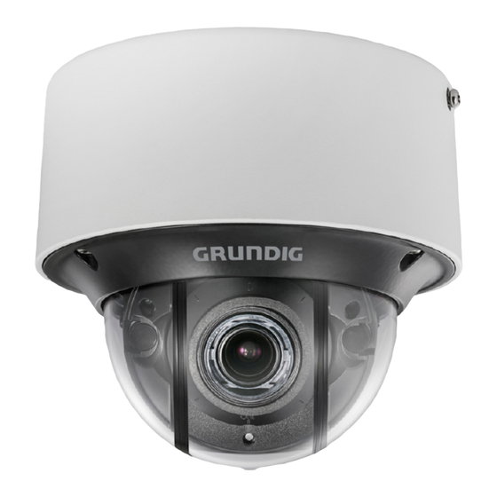
Network Dome Camera·Quick Start Guide 1 Appearance Description The overview of the dome camera is shown below: Overview... -
Page 10: Components
Network Dome Camera·Quick Start Guide Components Camera Components (1) - Page 11 Network Dome Camera·Quick Start Guide Camera Components (2) Description of Camera Components Description Description Mounting base Dome cover Lens Water-proof plug Side outlet cover Reset button Serial port Memory card slot Note: Press RESET about 10s when the camera is powering on or rebooting to restore the default settings, including the user name, password, IP address, port No., etc.
-
Page 12: Cables
Network Dome Camera·Quick Start Guide Cables This camera series has several camera models, each of which may have different cable group. The following figures and tables show the description of possible cables in this camera series. Overview of Cables (1) Overview of Cables (2) - Page 13 Network Dome Camera·Quick Start Guide Description of Cables Description BNC cable and interface 10M/100M self-adaptive Ethernet cable and RJ45 interface (PoE supported) Power supply cable and terminal block interface IN2: yellow/brown Alarm No.2 alarm input GND: yellow/black input/output 2A: yellow/orange Alarm cable output...
-
Page 14: Installation
Network Dome Camera·Quick Start Guide 2 Installation Before you start: ● Make sure the device in the package is in good condition and all the assembly parts are included. ● The standard power supply is 12V DC or 24V AC, please make sure your power supply matches with your camera. -
Page 15: Preparation
Network Dome Camera·Quick Start Guide Preparation Purpose: Before mounting, you have to disassemble the camera and install the memory card first. 2.1.1 Disassembling Steps: 1. Loosen the three screws on the edge of the dome cover with the screw driver. 2. -
Page 16: Memory Card Installation
Network Dome Camera·Quick Start Guide 2.1.2 Memory Card Installation Steps: 1. Rotate the camera body to completely expose the memory card slot. 2. Insert the memory card into the memory card slot, and push it to get it mounted. Memory Card Install the Memory Card 3. -
Page 17: Mounting
Network Dome Camera·Quick Start Guide Mounting 2.2.1 Ceiling Mounting 1. Attach the supplied drill template to the place where you want to fix the camera. 2. Drill the screw holes and the cable hole according to the drill template as the figure below. Drill Template Notes: ●... - Page 18 Network Dome Camera·Quick Start Guide Side Outlet Side Outlet 3. Fix the mounting base to the ceiling with the supplied screws. Ceiling Mounting Base Screws Install the Mounting Base 4. Align the camera body with the mounting base and rotate the camera body counterclockwise to get it fitted with the mounting base.
- Page 19 Network Dome Camera·Quick Start Guide Lock Screw Install the Camera Body 5. Connect the video output connector to the monitor and connect the power connector to the power supply to adjust the surveillance angle and image. 6. Adjust the surveillance angle and image according to the figures below.
- Page 20 Network Dome Camera·Quick Start Guide Zoom and Focus Adjustment Cameras of this series are equipped with a motor-driven lens. You can adjust the zoom and focus level on PTZ control panel by visiting the camera via web browser or client software. Zoom and Focus Adjustment via Web Browser 7.
-
Page 21: Wall Mounting
Network Dome Camera·Quick Start Guide 8. Tighten the lock screw to complete the installation. Lock Screw Figure 2-10 Complete the Installation 2.2.2 Wall Mounting Before you start: Wall mounting bracket is not included in package. If you choose this mounting type, you have to prepare a bracket first. The wall mounting bracket shown below is only for demonstration. - Page 22 Network Dome Camera·Quick Start Guide Size of the Mounting Base Figure 2-11 Steps: 1. Route the cables, install the wall mounting bracket, and secure the cap on the bracket. Wall Mounting Bracket Install Wall Mounting Bracket...
- Page 23 Network Dome Camera·Quick Start Guide 2. Align the screw holes of the mounting base with the corresponding screw holes of the cap. Mounting Base Install the Mounting Base 3. Secure the mounting base to the cap with screws. 4. Align the camera with the mounting base, and secure the camera with screws.
-
Page 24: Pendant Mouting
Network Dome Camera·Quick Start Guide 5. Connect the video output connector to the monitor and connect the power connector to the power supply to adjust the surveillance angle and image. 6. Adjust the image and focus. Please refer to step 6 in section 2.2.1 for more detailed information. - Page 25 Network Dome Camera·Quick Start Guide Size of the Mounting Base Steps: 1. Route the cables and install the pendant mounting bracket. Secure the cap on the bracket. Pendant Mounting Bracket Install the Pendant Mounting Bracket...
- Page 26 Network Dome Camera·Quick Start Guide 2. Align the screw holes of the mounting base with the corresponding screw holes of the cap. Mounting Base Install the Mounting Base 3. Secure the mounting base to the cap with screws. 4. Align the camera with the mounting base, and secure the camera with screws.
-
Page 27: Installation Of Network Cable Water-Proof Jacket (Optional)
Network Dome Camera·Quick Start Guide 5. Connect the video output connector to the monitor and connect the power connector to the power supply to adjust the surveillance angle and image. 6. Adjust the image and focus. Please refer to step 6 in section 2.2.1 for more detailed information. - Page 28 Network Dome Camera·Quick Start Guide Components O-Type Gasket Network Plug Waterproof Endcap Waterproof Rubber Gasket Lock Nut Network Cable from Router/Switch Steps: 1. Feed the plugless network cable ⑦ through the lock nut ⑥, waterproof rubber gasket ⑤ (the rubber gasket inset ridge must face the waterproof endcap), and the waterproof endcap ④...
-
Page 29: Installation Of Water-Proof Tape (Optional)
Network Dome Camera·Quick Start Guide waterproof endcap ④ to the camera’s network interface socket ① to finish installation. Align the snap and notch. i. Insert into ⑤ ④ ii. Secure with ⑥ ④ Camera Switch/Router Figure 2-20 Water-proof Accessory Installation 2.4 Installation of Water-proof Tape (Optional) Purpose: If the camera is installed outdoor, you can use supplied water-proof... - Page 30 Network Dome Camera·Quick Start Guide 1. Tear off the yellow release paper on the back of the water-proof tape. 2. Stretch the water-proof tape to reach twice the initial length. Initial Length Stretch Stretch Waterproof Tape Length After Stretching Figure 2-21 Stretch the Water-proof Tape 3.
- Page 31 Network Dome Camera·Quick Start Guide 4. Press the tape on both ends of the connector to make sure no water can get in as the figure below. Press Figure 2-23 Press the Water-proof Tape 5. Wrap the water-proof tape around the remaining unused cables tightly as the figure below.
- Page 32 Network Dome Camera·Quick Start Guide Press Figure 2-25 Press the Water-proof Tape...
-
Page 33: Setting The Network Camera Over The Lan
Network Dome Camera·Quick Start Guide 3 Setting the Network Camera over the Note: You shall acknowledge that the use of the product with Internet access might be under network security risks. For avoidance of any network attacks and information leakage, please strengthen your own protection. -
Page 34: Activating The Camera
Network Dome Camera·Quick Start Guide Activating the Camera You are required to activate the camera first by setting a strong password for it before you can use the camera. Activation via Web Browser, Activation via SADP, and Activation via Client Software are all supported. We will take activation via SADP software and Activation via Web Browser as examples to introduce the camera activation. -
Page 35: Activation Via Sadp Software
Network Dome Camera·Quick Start Guide Create a password and input the password into the password field. STRONG PASSWORD RECOMMENDED– We highly recommend you create a strong password of your own choosing (using a minimum of 8 characters, including upper case letters, lower case letters, numbers, and special characters) in order to increase the security of your product. - Page 36 Network Dome Camera·Quick Start Guide SADP Interface Figure 3-4 Note: The SADP software supports activating the camera in batch. Please refer to the user manual of SADP software for details. 3. Create a password and input the password in the password field, and confirm the password.
-
Page 37: Modifying The Ip Address
Network Dome Camera·Quick Start Guide You can check whether the activation is completed on the popup window. If activation failed, please make sure that the password meets the requirement and try again. Modifying the IP Address Purpose: To view and configure the camera via LAN (Local Area Network), you need to connect the network camera in the same subnet with your PC. - Page 38 Network Dome Camera·Quick Start Guide Modify the IP Address Figure 3-5 4. Input the password to activate your IP address modification. The batch IP address modification is supported by the SADP; please refer to the User Manual of SADP for details.
-
Page 39: Accessing Via Web Browser
Network Dome Camera·Quick Start Guide 4 Accessing via Web Browser System Requirement: Operating System: Microsoft Windows XP SP1 and above version CPU: 2.0 GHz or higher RAM: 1G or higher Display: 1024×768 resolution or higher Web Browser: Internet Explorer 8.0 and above version, Apple Safari 5.0.2 and above version, Mozilla Firefox 5.0 and above version and Google Chrome 18 and above version Steps:... - Page 40 Figure 4-2 Download Plug-in 6. Reopen the web browser after the installation of the plug-in and repeat steps 2 to 4 to login. Note: For more details about further configuration instructions, please refer to the User manual. QG-GD-CI-AT3637V-2018-01-06-V1-EN ©ABETECHS GMBH, DÜSSELDORF, GERMANY...
Need help?
Do you have a question about the GD-CI-AT3637V and is the answer not in the manual?
Questions and answers