Table of Contents
Advertisement
Quick Links
Advertisement
Table of Contents

Related Manuals for Grundig GD-CI-AT2505B


Summary of Contents for Grundig GD-CI-AT2505B
- Page 2 Use of this document and the subsequent results shall be entirely on the user’s own responsibility. Abetechs GmbH (Grundig Security) reserves the right to change the contents of this document without prior notice. Design and specifications are subject to change without prior notice.
- Page 3 OPEN SOURCE SOFTWARE LICENSE INFORMATION The software components provided with Grundig products may contain copyrighted software that is licensed under various open source software licenses. For detailed information about the...
- Page 4 You may obtain the complete corresponding open source part of a specific product from us for a period of three years after our last shipment of this product by sending an email to: info@grundig- security.com Safety and Installation Instructions...
- Page 5 Improper use or replacement of the battery may result in the hazard of explosion. Do not use any accessories that are not recommended by GRUNDIG. Do not modify the product in any way. If the product starts to smell or smoke comes out of the device, immediately stop using the product and disconnect it from the power supply to prevent fire or electric shocks.
- Page 6 Installation Instructions It is necessary to fix the device firmly if the product is installed on a wall or ceiling. Do not install the product on surfaces or in places that are vibrating. Do not install the product near radiation sources. Do not install the product near heat sources, like radiators or other equipment that produces some heat.
- Page 7 Special Installation Instructions for IP Cameras Make sure that the latest firmware is installed on the IP Device. You may get the latest firmware from www.grundig-security.com website or from techsupport@grundig-security.com.
-
Page 8: Table Of Contents
3.1 Wiring ................22 3.2 Activating the Camera ........... 23 3.2.1 Activation via Web Browser ........ 23 Activation via Grundig IP-Finder Tool ....24 3.3 Modifying the IP Address ..........26 4 Accessing via Web Browser ............28 4.1 Initializing the Memory Card ......... 30... -
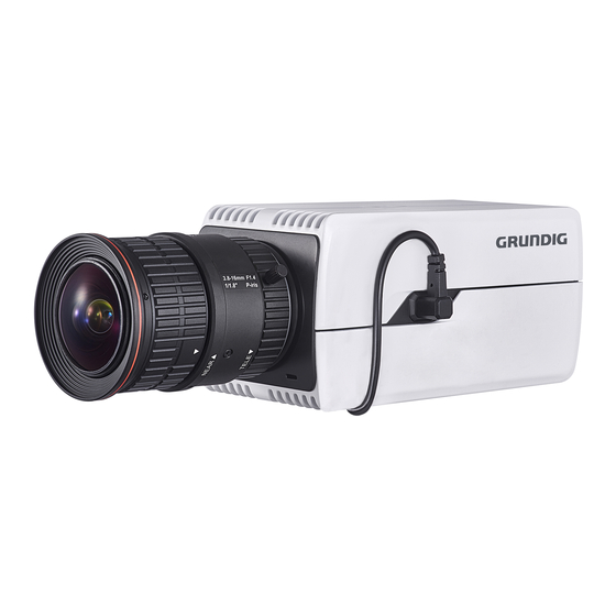
Page 9: Appearance Description
1 Appearance Description The overview of the box camera is shown below: Overview... - Page 10 Description Description Description Lens Mount Auto-iris Interface Power Indicator ¼-20 UNC Screw Hole (PoE Power Supply (12 VDC/24 802.3af) VAC) Reset ABF (Auto Back Focus) Memory Card Video Out Slot Grounding Screw Power Output VDC, 200mA) Grounding Audio Input Audio Output Grounding Alarm Output RS-485...
-
Page 11: Installation
2 Installation 2.1 Memory Card Installation Steps: Insert the memory card to memory card slot on the rear panel of the camera. (Optional) If you want to unmount the memory card, push to get it ejected. Memory Card Memory Card Installation... -
Page 12: Lens Installation
2.2 Lens Installation Lens Installation Steps: Fit the lens (not supplied) to the camera and rotate it to get it tightened. Notes: Install the adapter ring to the lens interface if a C-mount lens is used. A manual-iris lens can be directly installed to the camera without plugging the power cable of the auto-iris to the AI-interface. -
Page 13: Camera Mounting
2.3 Camera Mounting 2.3.1 Pendant Mounting Before you start: Pendant mount is not included in package. If you adopt this mounting style, you need to prepare a mounting bracket in advance. The shown pendant mount is for demonstration. Steps: Install the pendant mount to the ceiling with the supplied screws. Install the Mount Screw the camera to pendant mount and tighten the nut. -
Page 14: Wall Mounting
Adjusting Knob Adjust Surveillance Angle Loosen the adjusting knob. Hold the camera body to adjust panning and tilting position. Tighten the knob after adjustment. Adjust zoom and focus level. Refer to Section 2.5. 2.3.2 Wall Mounting Before you start: Wall mount is not included in package. If you adopt this mounting style, you need to prepare a mounting bracket in advance. - Page 15 Pedestal Separate Pedestal 2. Fix the pedestal to camera body. Fix Pedestal to Camera 3. Install the wall mount to wall. 4. Install the pedestal together with the camera back to wall mount. Install Camera to Wall Mount 5. Adjust the surveillance angle. Loosen tilt adjusting screw.
-
Page 16: Mounting With Housing
Tilt Adjusting Screw Pan Adjusting Screw Adjust Surveillance Angle 6. Adjust zoom and focus level. Refer to Section 2.5. 2.4 Mounting with Housing Before you start: The shown housing is not included in package. You need to prepare one if you adopt this mounting style. Also, for housing mounting, you need to prepare suitable brackets in advance. - Page 17 Install Camera to Mounting Plate Screw the mounting plate together with the camera back to the housing. Note: Push the camera as close to the window as possible. Window Cable Outlet Install Camera to Housing Connect and route cables through the cable outlet of the housing.
- Page 18 For network, alarm input and output, and audio input and output, plug corresponding plugs to the rear panel of the camera. See Figure 1-1. For power supply and RS-485, see the following figure.
- Page 19 Figure 2-11 Wiring Board in Housing Buckle the housing. Install the housing to surveillance scene. Using brackets, the housing supports wall mounting, pole mounting, and pendant mounting. The brackets are shown in the figures below: Wall Mount Horizontal Pole Mount Pendant Mount...
- Page 20 Install the bracket onto the wall/ceiling/pole. The wall mounting bracket, loop mounting bracket, and the pendent bracket are shown in the figures below. Figure 2-12 Install the Bracket to Mounting Place Fix the housing (with camera) onto the bracket with the supplied screws.
-
Page 21: Zoom And Focus Adjustment
Figure 2-13 Fix the Housing to Brackets 2.5 Zoom and Focus Adjustment Steps: Power on the camera. Connect the video out interface of the camera to the installation display device. - Page 22 Adjust the Zoom Lever and Focus Lever according to the image on the display device. Note: For the camera equipped with the auto iris, it is suggested you change the iris mode to manual from the camera menu (accessed via web browser), and re-change it back to auto iris after you adjust the focus by the focus lever.
-
Page 23: Setting The Network Camera Over The Lan
3 Setting the Network Camera over the Note: You shall acknowledge that the use of the product with Internet access might be under network security risks. For avoidance of any network attacks and information leakage, please strengthen your own protection. If the product does not work properly, contact your dealer or the nearest service center for help. -
Page 24: Activating The Camera
Activation via Web Browser and Activation via Grundig IP-Finder Tool are supported. We will take activation via Grundig IP-Finder Tool and Activation via Web Browser as examples to introduce the camera activation. -
Page 25: Activation Via Grundig Ip-Finder Tool
4. Confirm the password. 5. Click OK to save the password and enter the live view interface. Activation via Grundig IP-Finder Tool The Grundig IP-Finder Tool is used for detecting the online device and activating the camera. - Page 26 Get the Grundig Finder Tool from the supplied disk or the official website and install the software according to the prompts. Follow the steps to activate the camera, please refer to the User manual for other two activation methods. Steps: 3.
-
Page 27: Modifying The Ip Address
To view and configure the camera via LAN (Local Area Network), you need to connect the network camera in the same subnet with your Use the Grundig IP-Finder Tool to search and change the IP address of the device. We take modifying the IP Address via Grundig IP-Finder as an example to introduce the IP address modification. - Page 28 Modify the IP Address 4. Input the admin password and click Update to activate your IP address modification. The batch IP address modification is supported by the Grundig IP- Finder. Please refer to the User Manual of Grundig IP-Finder for details.
-
Page 29: Accessing Via Web Browser
4 Accessing via Web Browser System Requirement: Operating System: Microsoft Windows XP SP1 and above version CPU: 2.0 GHz or higher RAM: 1G or higher Display: 1024×768 resolution or higher Web Browser: Internet Explorer 8.0 and above version, Apple Safari 5.0.2 and above version, Mozilla Firefox 5.0 and above version and Google Chrome 18 and above version Steps:... - Page 30 4. Click Login. Login Interface 5. Install the plug-in before viewing the live video and managing the camera. Please follow the installation prompts to install the plug- Note: You may have to close the web browser to finish the installation of the plug-in.
-
Page 31: Initializing The Memory Card
If the memory card status displays as Uninitialized, tap to initialize it. The status will then change to Normal. You can then start recording any event triggered video in the camera such as motion detection. WWW.GRUNDIG-SECURITY.COM QG-GD-CI-AT4505B-2019-07-24-V3-EN ©ABETECHS GMBH, DÜSSELDORF, GERMANY...
Need help?
Do you have a question about the GD-CI-AT2505B and is the answer not in the manual?
Questions and answers