
Related Manuals for CyberView RP-119QD


Summary of Contents for CyberView RP-119QD
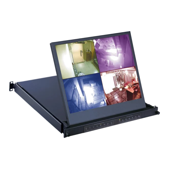
- Page 1 KVM switch and rackmount screen technology User Manual 19” LCD RP-119QD 1U Quad Display Drawer Options : - DC power Designed and manufactured by Austin Hughes UM-CV-751-RP-119QD-Q421V1 www.austin-hughes.com...
- Page 2 ■ Re-position or relocate the receiving antenna. ■ Increase the separation between the equipment and receiver. ■ Connect the equipment into an outlet on a circuit diff erent from that to which the receiver is connected. UM-CV-751-RP-119QD-Q421V1 www.austin-hughes.com...
-
Page 3: Table Of Contents
Contents Contents < Part. 1 > RP-119QD Package Content Structure Diagram & Dimension Installation < Part. 2 > Specifi cations / OSD Product Specifi cations On-screen Display Operation ( OSD ) < Part. 3 > Options P.10 DC Power : 12V / 24V / 48V / 125V <... - Page 4 fi rst, not directly on the parts you are cleaning. Gently wipe the surface. Use as little pressure as possible. Wait until your monitor is completely dry before plugging it in and powering it up. UM-CV-751-RP-119QD-Q421V1 www.austin-hughes.com...
-
Page 5: Package Content
< Part 1 > < 1.1 > Package Content RP-119QD RP-119QD unit X 1 - 6ft VGA cable X 1 - Power cord X 1 - M6 screw, cage nut & cup washer X 8 The above package content is only for the pure model ( VGA only ). - Page 6 Weight 442 x 650 x 44 mm 595 x 860 x 140 mm 12.5 kg 18.5 kg RP-119QD series 17.4 x 25.6 x 1.73 inch 23.4 x 33.9 x 5.5 inch 27.5 lb 40.7 lb The weight is only for the pure models. It varies with accessories & options such as DC power.
-
Page 7: Installation
RP-119QD < 1.3 > Installation - How to install Installation Slides Step ■ Insert the left and right rear mounting brackets into the display drawer Step ■ Measure the depth of the front and rear mounting rails. ■ Align each rear mounting bracket to a suitable length. -
Page 8: Product Specifi Cations
Environmental Operating Temperature 0 to 55°C degree Conditions Humidity 20~90%, non-condensing Altitude 16,000 ft Storage / Non-operating Temperature -20 to 60°C degree Humidity 5~90%, non-condensing Altitude 40,000 ft Shock 10G acceleration (11ms duration) Vibration 10~300Hz 0.5G RMS random UM-CV-751-RP-119QD-Q421V1 www.austin-hughes.com... - Page 9 RP-119QD Physical Product ( W x D x H ) 442 x 650 x 44 mm Specifi cation 17.4 x 25.6 x 1.73 inch Packing ( W x D x H ) 595 x 860 x 140 mm 23.4 x 33.9 x 5.5 inch Net Weight 12.5 kg / 28 lb...
- Page 10 Intentionally Left Blank UM-CV-751-RP-119QD-Q421V1 www.austin-hughes.com...
-
Page 11: On-Screen Display Operation ( Osd )
< 2.2 > On-screen Display Operation ( OSD ) RP-119QD LCD OSD Menu Power light Green = On Orange = Power saving Membrane Switch Function Power on / off LCD Display the OSD menu Scrolls through menu options and adjusts the displayed control... - Page 12 OSD time out : Adjust the screen timeout OSD transparency : Adjust the screen transparency OSD size : Adjust the screen size - Normal / Small OSD rotation : Rotate the screen - 90° / 180° / 270° UM-CV-751-RP-119QD-Q421V1 www.austin-hughes.com...
- Page 13 < 2.2 > On-screen Display Operation ( OSD ) RP-119QD Reset Reset : Return the adjustment back to factory setting PIP ( Not Applicable to F17 / MF17 ) PIP mode : Enter into PIP / PBP setting - PIP MODE /...
-
Page 14: Part. 3 > Options
Output current: 4.16A 4.16A 4.16A 6.25A Effi ciency For DC power option : ( 1 ) If the unit with LCD, earthing may be required ( 2 ) DC option excludes AC power adapter and power cord. P.10 UM-CV-751-RP-119QD-Q421V1 www.austin-hughes.com... -
Page 15: Part 4 > Quad Display Connection & Operation
< Part 4 > Quad Display Connection & Operation < 4.1 > QD Connection RP-119QD 1. VCR in : This BNC connector is connected to video output from VCR/DVR. A pre-recorded quad screen signal from a tape can be played back through a VCR/DVR and displayed on the video output channels. Push the VCR button (#2) to switch the device to VCR Playback mode. -
Page 16: Qd Alarm Connection & Operation
*. In order to make use of the alarm called full screen display function, the VIDEO IN connector from the VCR has to be connected to LIVE monitor connector of the device. If more than one sensor are trigged, VCR will then record all the events in full screen mode accordingly. P.12 UM-CV-751-RP-119QD-Q421V1 www.austin-hughes.com... - Page 17 < 4.2 > QD ALARM Connection & Operation RP-119QD 3 Sensor Activated Alarm The unit is equipped with 4 alarm sensor inputs. If any alarm is activated: ■ the built-in buzzer and the alarm output control relay contact will be activated.
-
Page 18: Qd Remote Control Connection & Operation
< 4.3 > QD Remote Control Connection & Operation Rear Panel h i - z RS-232 1 2 3 4 ALARM monitor dc 12V, 1amp RS-232 Cable Wire Computer Remote Keypad P.14 UM-CV-751-RP-119QD-Q421V1 www.austin-hughes.com... - Page 19 < 4.3 > QD Remote Control Connection & Operation RP-119QD The device can be controlled via the male type 9 pin D-sub/RS-232 connector to a computer using ASCII code. 1. Pin assignment of the male type 9 pin D-sub connector:...
- Page 20 CH3 & 4 in Freeze mode XX-DF Buzzer/VCR ON CH1, 3, & 4 in Freeze mode XX-7F Security lock ON CH2, 3, & 4 in Freeze mode XX-3F Buzzer & Security lock ON (Stop) CH1, 2,3, & 4 in Freeze mode P.16 UM-CV-751-RP-119QD-Q421V1 www.austin-hughes.com...
- Page 21 < 4.3 > QD Remote Control Connection & Operation RP-119QD 2.3 The confi guration of the status code for both normal and alarm operations: There are total 2 bytes of the status codes. Byte one, the fi rst 8 bits, shows the current status of the operation modes that the unit is in.
- Page 22 Sensor activated Alarm Video Loss Alarm 0001 = CH1 activated 0001 = CH1 activated 0010 = CH2 activated 0010 = CH2 activated 0100 = CH3 activated 0100 = CH3 activated 1000 = CH4 activated 1000 = CH4 activated P.18 UM-CV-751-RP-119QD-Q421V1 www.austin-hughes.com...
-
Page 23: Qd Osd Operation
< 4.4 > QD OSD Operation RP-119QD Quad Display Control < > Setup Lock: Security locks out button. Push this button for 2 seconds to enable control panel lock out function. Push this button again for 2 seconds to disable the function. -
Page 24: Qd On-Screen Menu
HH:MM:SS” format for PAL model. 1.4 TITLE/TIME/DATE disable and enable on LIVE and QUAD video output channel: The Title/Time/Date display on each output channel can be enabled or disabled by setting ON or OFF in the correspond- ing entry. P.20 UM-CV-751-RP-119QD-Q421V1 www.austin-hughes.com... - Page 25 < 4.5 > QD On-screen Menu RP-119QD 2 Page 2 of the setup menu- Alarm Setting Push Setup buttons (#1, #2) simultaneously and push (#1) button again to display page 2 of the setup menu on the screen. This Alarm Setting menu is used to set the desired alarm confi guration like sensor type, sensor sensitivity, alarm hold duration, and buzzer.
- Page 26 fi rst starts with a quad screen and then continues to display each camera input in full screen, and then gets back to quad screen and so on. Press the Sequence button (#3) to OFF to release this mode. P.22 UM-CV-751-RP-119QD-Q421V1 www.austin-hughes.com...
-
Page 27: Qd Vcr Operation
< 4.6 > QD VCR Operation RP-119QD Zoom on VCR playback operation: Push VCR button (#2) to ON will switch the device to VCR playback mode. Under this mode, if the device is on quad display mode, a pr-recorded quad display video in the tape will be shown on the screen. If the device is in Full screen display mode, push any channel select buttons (#5) will select and expand the corresponding quadrants of the pre- recorded video to full screen display. - Page 28 The company reserves the right to modify product specifi cations without prior notice and assumes no responsibility for any error which may appear in this publication. All brand names, logo and registered trademarks are properties of their respective owners. Copyright 2021 Austin Hughes Electronics Ltd. All rights reserved. P.24 UM-CV-751-RP-119QD-Q421V1 www.austin-hughes.com...
Need help?
Do you have a question about the RP-119QD and is the answer not in the manual?
Questions and answers