Table of Contents
Advertisement
Quick Links
®
SIMEX
USER MANUAL for
digital indicator
with 0/4 ÷ 20 mA inputs
●
S-Toolkit v. 1.7.0 or higher
●
SWP-99 - X100 - 1 - X - XX1
device type:
2.10 b972
firmware version:
or higher
Read the user's manual carefully before starting to use the unit or software.
Producer reserves the right to implement changes without prior notice.
V.2.05
14.08.2008
Advertisement
Table of Contents

Related Manuals for Simex SWP-99


Summary of Contents for Simex SWP-99
- Page 1 0/4 ÷ 20 mA inputs ● S-Toolkit v. 1.7.0 or higher ● SWP-99 - X100 - 1 - X - XX1 device type: 2.10 b972 firmware version: or higher Read the user's manual carefully before starting to use the unit or software.
-
Page 2: Table Of Contents
User manual for Digital Indicator and cooperating software CONTENTS I. USER MANUAL FOR “SWP-99” DIGITAL INDICATOR..........4 1. BASIC REQUIREMENTS AND USER SAFETY..................4 2. GENERAL CHARACTERISTICS........................5 3. TECHNICAL DATA............................6 4. DEVICE INSTALLATION..........................8 4.1. UNPACKING............................8 4.2. ASSEMBLY............................8 4.3. CONNECTION METHOD.........................11 4.4. MAINTENANCE..........................14 5. - Page 3 User manual for Digital Indicator and cooperating software 3.5.3.Configuring all channels......................51 3.6. UPDATING SOFTWARE OF SWP-99 DEVICE................52 Explanation of symbols used in the manual: - This symbol denotes especially important guidelines concerning the installation and operation of the device. Not complying with the guidelines denoted by this symbol may cause an accident, damage or equipment destruction.
-
Page 4: User Manual For "Swp-99" Digital Indicator
User manual for Digital Indicator and cooperating software I. USER MANUAL FOR “ SWP-99 ” DIGITAL INDICATOR 1. BASIC REQUIREMENTS AND USER SAFETY - The manufacturer is not responsible for any damages caused by inappropriate installation, not maintaining the proper technical condition and using the unit against its destination. -
Page 5: General Characteristics
2. GENERAL CHARACTERISTICS • Multifunctional SWP-99 designed for displaying current values and presentation of technological parameter trends in graphic form. All measured parameters must be available in 0-20 mA or 4-20 mA (this can be for example pressures, levels, humidity, temperatures, forces, etc.). -
Page 6: Technical Data
User manual for Digital Indicator and cooperating software 3. TECHNICAL DATA Power supply voltage 85...230...260V AC/DC; 50 ÷ 60 Hz (depending on version) or 19... 24 ...50V DC; 16V... 24 ...35V AC External Fuse (required) T - type, max. 2 A Power consumption typically 7 VA;... - Page 7 User manual for Digital Indicator and cooperating software This is a class A unit. In housing or a similar area it can cause radio frequency interference. In such cases the user can be requested to use appropriate preventive measures. Carefully check that the insulation used with the unit (Fig. 3.1) meets the expectations and if necessary use appropriate measures of overvoltage protection.
-
Page 8: Device Installation
Attached with the unit please find: assembly brackets - 2 pieces, – warranty, – user’s manual for SWP-99 unit (device) – user’s manuals for cooperating software, – CD-ROM with the aforesaid manual in PDF format and installation files of cooperating –... - Page 9 User manual for Digital Indicator and cooperating software In order to assembly the unit, a 90,5 x 90,5 mm mounting hole (Fig. 4.1) must be prepared. The thickness of the material of which the panel is made must not exceed 5mm.
- Page 10 User manual for Digital Indicator and cooperating software GOOD back side of device connector WRONG back side of device connector Fig. 4.3. Connectors removing method 115 mm Fig. 4.4. Minimum distances when assembly of a number of units...
-
Page 11: Connection Method
User manual for Digital Indicator and cooperating software 4.3. CONNECTION METHOD Caution - Installation should be conducted by qualified personnel . During installation all available safety requirements should be considered. The fitter is responsible for executing the installation according to this manual, local safety and EMC regulations. - Page 12 User manual for Digital Indicator and cooperating software Use of screened signal cables is recommended. Signal cable screens should be connected to the earthing only at one of the ends of the screened cable. In the case of magnetically induced interference the use of twisted couples of signal cables (so-called “spirals”) is recommended.
- Page 13 User manual for Digital Indicator and cooperating software Depending on version: 85...230...260V AC/DC or 19...24...50V DC; 16...24...35V AC FUSE Fig. 4.7. Connection of power supply additional terminals (internally connected) 15 16 17 18 19 20 21 22 23 24 25 26 external 28 29 30 31 32 34 35 36 37 38...
-
Page 14: Maintenance
User manual for Digital Indicator and cooperating software RS 485 12 13 RS232/485 interface Fig. 4.10. Connection of RS-485 transmission signals The SWP-99 device supports the following converters: USB / RS-485 converter (SRS-USB/4-Z45) – RS-232 / RS-485 converter ( SRS-2/4-Z45 ) – 4.4. MAINTENANCE The unit does not have any internal replaceable or adjustable components available to the user. -
Page 15: Front Panel Description
User manual for Digital Indicator and cooperating software 5. FRONT PANEL DESCRIPTION display programming pushbuttons Key designation and functions Symbols used in the manual: [ESC/MENU] and Functions: MENU MENU • go to main menu (press and hold by at least 2 sec.), •... -
Page 16: Principle Of Operation
User manual for Digital Indicator and cooperating software 6. PRINCIPLE OF OPERATION After turning the power supply on, the logo and basic unit data are showed on the display, then the unit goes to the measurement mode. 6.1. MEASUREMENT MODE In the measurement mode the unit executes the measurement of values of signals connected to current inputs, hereafter called measurement channels (the number of available channels depends on the unit version). -
Page 17: Modes Of Result Presentation
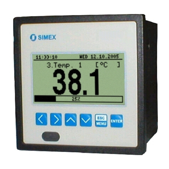
User manual for Digital Indicator and cooperating software 6.2. MODES OF RESULT PRESENTATION The results of measurements conducted for active channels are presented in numeric or graphic (graph or bar) form. Selection of one of the available results presentation modes can be made using the [^] and [v] keys in the measurement mode. - Page 18 User manual for Digital Indicator and cooperating software channel name current date current time channel number unit name measure result bargraph in numerical mode percentage rate of measure result to nominal input range Fig. 6.6. Unit in ”Single channel” result presentation mode Exceeding the nominal measurement range (Fig.
-
Page 19: Graph" Mode
User manual for Digital Indicator and cooperating software Functions of keys in "Single channel" mode: • go to main menu (press and hold for approx. 2 seconds), MENU • change channel number, • change results presentation mode. 6.2.2. ”Graph” mode In this mode (Fig. - Page 20 User manual for Digital Indicator and cooperating software warning message informing that input allowable range is exceeded arows inform that input allowable range is exceeded Fig. 6.10. Exceeding the upper limit of the allowable measurement range The display shows points corresponding to measurement results. Directly after switching to the "...
-
Page 21: Channels List" Mode
User manual for Digital Indicator and cooperating software Changes of settings configuring the operation of a given channel and operation stoppage are signalled in the form of a vertical line (Fig. 6.12). If the settings of the horizontal scale (time scale) will be too big (time/point) in relation to speed of changes of the measurement signal, the graph can become illegible. -
Page 22: Device Programming
User manual for Digital Indicator and cooperating software or in the form of a bar (percentage) depending on the settings in the " Channels list options " menu. Graphic indicators (bars) always show the measurement result to the nominal measurement range ratio. current time current date channel number... - Page 23 User manual for Digital Indicator and cooperating software DESCRIPTION OF RESULTS PRESENTATION MENU MODES section. In order to get to the configuration menu of selected results presentation mode, press the [ESC/MENU] key in the current results presentation mode. The unit's main menu (Fig. 7.1) enables necessary information about the unit to be obtained and allows the setting of all parameters of the unit related to operation of measurement channels, communications using the RS 485 interface, LCD display, access settings, and other.
-
Page 24: Parameters Edition
User manual for Digital Indicator and cooperating software • Change of current item in the menu (selecting a lower level menu or parameter for editing). The selected option is distinguished by displaying the option name in negative (bright lettering on dark background). The function of the [ENTER] key depends on the type of current menu item: ENTER •... -
Page 25: Text Parameters
User manual for Digital Indicator and cooperating software edited switch parameter selected LIST-type is outlined and blinking parameter Fig. 7.5. Editing "LIST" - type switching parameter Functions of keys when editing numeric and switching parameters: • Selecting the decimal position of the edited numeric parameter. Selected item is distinguished with brackets and flashes. -
Page 26: Slider" - Type Parameters
User manual for Digital Indicator and cooperating software • Start editing the character for the selected position ENTER • Confirm the changes and finish parameter editing (when option "Save" is distinguished with brackets and flashes). • Cancel changes (at any time). MENU edited position is outlined and blinking... -
Page 27: Description Of Results Presentation Modes Menu
User manual for Digital Indicator and cooperating software Functions of keys when editing "SLIDER" - type parameters: • Change the value of edited parameter. The edited parameter placed in brackets and flashes. ENTER • Finish editing parameter. • Cancel changes (at any time). MENU 7.2. -
Page 28: Results Presentation Modes Menu Structure
User manual for Digital Indicator and cooperating software Fig. 7.10. "Channels list options" menu 7.3. RESULTS PRESENTATION MODES MENU STRUCTURE Main menu Power on Initialization MENU Channel selection Mode: ”Single channel” ENTER Parameter MENU Graph options Scale MENU Mode: ”Graph” edition ENTER MENU... -
Page 29: Input Settings" Menu
User manual for Digital Indicator and cooperating software ”Backlight” - this option allows one to define when the LCD backlight is to be switched on. The following possibilities are available: ”permanent” - backlight always On, ”temporary” - backlight is turned on when any key on the unit is pressed and switches Off after 1 minute since the last activation of the keys, and turned on for approximately 10 seconds when the unit is switched on. - Page 30 User manual for Digital Indicator and cooperating software - current inputs, displayed value is defined by “ Hi value ”, ”0-20 mA”,”4-20 mA” “Lo value” and "Dec. point" parameters. - these parameters define the values displayed for maximum (Hi), and ”Hi value”...
-
Page 31: Date & Time Settings" Menu
User manual for Digital Indicator and cooperating software ”Upper ext.” = 1 mA ”Lower ext.” = 3mA nominal measurement range (4-20 mA) permissible measurement range measurement result is displayed regardless on nominal range exceeding display display message ”-Lo-” message ”-Hi-” Fig. - Page 32 User manual for Digital Indicator and cooperating software ”Baud rate” - this option defines the RS-485 serial interface transmission speed. 8 possibilities are available: ” 1200 ”, ” 2400 ”,” 4800 ” , ” 9600 ”, ” 19200 ” , ” 38400 ”, ” 57600 ”, ” 115200 ” b/sec. Default baud rate value is 115200 b/sec.
-
Page 33: Access Setup" Menu
User manual for Digital Indicator and cooperating software 7.4.6. ”Access setup” menu This menu contains options controlling access to the unit’s adjustable parameters: ”Password for menu access” - menu access password (4-digit number). If the parameter is set to “0000” the password is disabled. If the parameter is different from “... -
Page 34: Main Menu Structure
User manual for Digital Indicator and cooperating software 7.5. MAIN MENU STRUCTURE Result presentation mode Press and hold at least 2 seconds MENU MENU 4-digit user password entering (if it is different from „0000”) 0 _ _ _ ENTER ENTER Parameters MENU Device information... -
Page 35: The Modbus Protocol Handling
User manual for Digital Indicator and cooperating software 8. THE MODBUS PRO TOCOL HANDLING Transmission parameters: 1 start bit, 8 data bits, 1 stop bit, no parity control Baud rate: selectable from: 1200 to 115200 bits/second Transmission protocol: MODBUS RTU compatible The device parameters and measurement result are available via RS-485 interface, as HOLDING-type registers of Modbus RTU protocol. - Page 36 User manual for Digital Indicator and cooperating software Register Write Range Register description Control registry for time-related settings: 0 - startup of continued update of registries 18h ÷ 1Eh by internal clock (current time and date), 80h - stopping update of registries 18h ÷ 1Eh by internal clock (automatically after writing one of 18h ÷...
-
Page 37: Transmission Errors Handling
User manual for Digital Indicator and cooperating software Register Write Range Register description “Name” parameter in “Inputs settings” submenu for channel 1; Character Higher byte – character No. 1; Lower byte – character No. 2 “Name” parameter in “Inputs settings” submenu for channel 1; Character Higher byte –... -
Page 38: Examples Of Query/Answer Frames
User manual for Digital Indicator and cooperating software 01h - illegal function (only functions 03h, 06h and 10h are available), 02h - illegal register address 03h - illegal data value 08h - no write permission ( see: “Config change” parameter in the “RS485 port settings” menu) 8.3. - Page 39 User manual for Digital Indicator and cooperating software ADDR FUNC REG H,L DATA H,L CRC L,H 3. Read of the displayed value (measurement) for channel 1, the device address = 01h: ADDR FUNC REG H,L COUNT H,L CRC L,H The answer: ADDR FUNC BYTE C...
- Page 40 User manual for Digital Indicator and cooperating software DATA H1,L1 DATA H2,L2 DATA H3,L3 DATA H4,L4 DATA H5,L5 CRC L,H DATA H1, L1 - 47h registry (43h - character "C", 68h - character "h"), DATA H2, L2 - 48h registry (61h - character "a", 6Eh - character "n"), DATA H3, L3 - 49h registry (6Eh - character "n", 65h - character "e"), DATA H4, L4 - 4Ah registry (6Ch - character "l", 20h - space "...
-
Page 41: User's Settings List
User manual for Digital Indicator and cooperating software 9. USER'S SETTINGS LIST Description Parameter Description Value page Parameters in the "Graph options” menu Scale Setting time scale Parameters in the "Channels list options” menu Display Method of displaying results Parameters in the “Device information ” menu Version Device firmware version Serial no... - Page 42 User manual for Digital Indicator and cooperating software Description Parameter Description Value page Upper ext. Upper extension of measurement range Lower ext. Lower extension of measurement range Settings for Channel 3 in “Inputs settings” menu Name Measurement channel name Unit Unit for measured value Input type Type of input/sensor...
- Page 43 User manual for Digital Indicator and cooperating software Description Parameter Description Value page Upper ext. Upper extension of measurement range Lower ext. Lower extension of measurement range Settings for Channel 6 in “Inputs settings” menu Name Measurement channel name Unit Unit for measured value Input type Type of input/sensor...
- Page 44 User manual for Digital Indicator and cooperating software Description Parameter Description Value page Upper ext. Upper extension of measurement range Lower ext. Lower extension of measurement range Parameters in the “RS485 port settings” menu Address Device address Baud rate Baud rate Resp.
-
Page 45: User Manual For "S-Toolkit
1. GENERAL CHARACTERISTICS The S-Toolkit software enables configuration reading and writing operations, updating the device firmware and obtaining basic information on SWP-99 -type devices through RS485 serial interface. This application enables to quickly and easily define device parameters in one of three possible configuration models. -
Page 46: Using Program
User manual for Digital Indicator and cooperating software 3. USING PROGRAM Read current settings from device, from file or import settings from flash disk Write configuration set to device, to file or export settings to flash disk Fig. 3.1. Program main window There are four tabs in the central part of program window: •... -
Page 47: Inputs Settings" Tab
User manual for Digital Indicator and cooperating software [Export] • - saves the settings shown in the Inputs settings tab and writes the configuration set to the FlashDrive; [Close] • - exits the program. Status information concerning currently performed operation is shown in the bottom of the window. -
Page 48: Logging Setup" Tab
In the central part of the tab (in a separated panel) there are fields for configuring device parameters. The parameters can be configured in three modes. Detailed description of individual parameters can be found in the user manual for device SWP-99 . •... -
Page 49: Interface Options" Tab
In order for communication between the program and the device to be possible, the address and baud rate set in the program must be same as the ones set in the SWP-99 device. Display options •... -
Page 50: Device Information" Tab
User manual for Digital Indicator and cooperating software If the SWP-99 device clock shows later time than computer's system clock, then the synchronization (in this case reversing the SWP-99 clock) will cause all data recorded by device after the time set during synchronization to be deleted. -
Page 51: Configuration Modes
SWP-99 device. Therefore perform one of the aforesaid operations prior to configuring the next group of selected channels. Due to the time of writing the configuration to SWP-99 device it is recommended to write the set configuration to file. 3.5.3. Configuring all channels After switching to all-channels configuration mode, the values for most recently configured channel remain in the configuration fields. - Page 52 In exceptional cases (update interrupted or unit does not operate after update) contact the manufacturer. The newest version of SWP-99 device firmware is available at producer homepage. The USB driver update section in the Device information tab enables USB interface driver update.
- Page 53 User manual for Digital Indicator and cooperating software...
- Page 54 User manual for Digital Indicator and cooperating software...
- Page 55 User manual for Digital Indicator and cooperating software...
- Page 56 ® SIMEX SIMEX Sp. z o.o. , ul. Wielopole 7 PL - 80-556 Gdańsk, Poland tel. : (+48 58) 762-07-77, fax: (+48 58) 762-07-70 http://www.simex.com.pl, e-mail: info@simex.com.pl...
Need help?
Do you have a question about the SWP-99 and is the answer not in the manual?
Questions and answers