Table of Contents
Advertisement
Quick Links
Assisting the automation
Microlectra bv.
industry since 1986
User manual
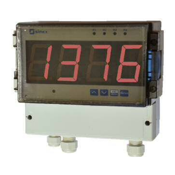
METER
SRT-457
Firmware: v.5.18 or higher
Input type: Pt100/500/1000
Wall mounting case IP 65 / IP 67
Read the user's manual carefully before starting to use the unit or software.
Producer reserves the right to implement changes without prior notice.
Microlectra bv.
Augustapolder 12. 2992 SR Barendrecht. The Netherlands.
www.microlectra.nl
info@microlectra.nl
2013.06.06
SRT-457_INSSXEN_v.2.06.001
Advertisement
Table of Contents

Related Manuals for Simex SRT-457


Summary of Contents for Simex SRT-457
- Page 1 Assisting the automation Microlectra bv. industry since 1986 User manual METER SRT-457 Firmware: v.5.18 or higher Input type: Pt100/500/1000 Wall mounting case IP 65 / IP 67 Read the user's manual carefully before starting to use the unit or software.
-
Page 2: Table Of Contents
User manual - METER SRT-457 CONTENTS 1. BASIC REQUIREMENTS AND USER SAFETY..................3 2. GENERAL CHARACTERISTICS........................4 3. TECHNICAL DATA............................4 4. DEVICE INSTALLATION..........................5 4.1. UNPACKING............................6 4.2. ASSEMBLY............................6 4.3. CONNECTION METHOD........................7 4.4. MAINTENANCE..........................12 5. FRONT PANEL DESCRIPTION........................12 6. PRINCIPLE OF OPERATION........................13 6.1. MEASUREMENT MODE........................13... -
Page 3: Basic Requirements And User Safety
User manual - METER SRT-457 Explanation of symbols used in the manual: - This symbol denotes especially important guidelines concerning the installation and operation of the device. Not complying with the guidelines denoted by this symbol may cause an accident, damage or equipment destruction. -
Page 4: General Characteristics
To allow user to change presets without opening the cover, an IR sensor is mounted. Remote controller keyboard is equivalent to the device keyboard (Note, that remote controller is not a part of the SRT-457 set it is an additional equipment). -
Page 5: Device Installation
User manual - METER SRT-457 Display LED, 4 digit, 57mm height, red Data memory non-volatile memory, EEPROM type Protection level F-type casing:IP 65 T-type casing:IP 67 Housing type Wall mounted, T-type or F-type Housing material ABS + fibreglass Housing dimensions F-type casing: 213 x 185 x 118.2 mm... -
Page 6: Unpacking
User manual - METER SRT-457 - All installation works must be conducted with a disconnected power supply. - Protecting the power supply connections against unauthorized persons must be taken into consideration. 4.1. UNPACKING After removing the unit from the protective packaging, check for transportation damage. Any transportation damage must be immediately reported to the carrier. -
Page 7: Connection Method
User manual - METER SRT-457 230 mm 96.5 mm 212 mm Figure 4.2. Device and assembly dimensions of T-type case 4.3. CONNECTION METHOD Caution - Installation should be conducted by qualified personnel . During installation all available safety requirements should be considered. The fitter is responsible for executing the installation according to this manual, local safety and EMC regulations. - Page 8 User manual - METER SRT-457 - Unused terminals (marked as n.c.) must not be used for connecting any connecting cables (e.g. as bridges), because this can cause damage to the equipment or electric shock. - If the unit is equipped with housing, covers and sealing to, protecting against water intrusion, pay special attention to their correct tightening or clamping.
- Page 9 User manual - METER SRT-457 RS - 485 (optional) +24V ±5% Pt100/500/1000 Power DATA+ max = 100mA supply DATA- (depending on version) 7 8 9 10 11 12 13 14 15 16 n.c. Pt100/500/1000 Figure 4.4. Terminals description (relay outputs)
- Page 10 User manual - METER SRT-457 FUSE FUSE Depending on version: 85...230...260V AC/DC or 19...24...50V DC; 16...24...35V AC Figure 4.6. Connection of power supply and relays Contacts of relay outputs are not equipped with spark suppressors. While use the relay outputs for switching of inductive loads (coils, contactors, power relays, electromagnets, motors etc.) it is required...
- Page 11 User manual - METER SRT-457 10 11 10 11 LED 10 mA voltage input 24 V Logic controller Figure 4.8. Example of OC-type outputs connection Temperature sensor can be connected to the device in typical 4-wire circuit (Figure 4.9a) or 3-wire circuit (Figure 4.9b).
-
Page 12: Maintenance
User manual - METER SRT-457 4.4. MAINTENANCE The unit does not have any internal replaceable or adjustable components available to the user. Pay attention to the ambient temperature in the room where the unit is operating. Excessively high temperatures cause faster ageing of the internal components and shorten the fault-free time of the unit's operation. -
Page 13: Principle Of Operation
Configuration of the device (via menu or RS-485 interface) do not stops measures . 6.2. DETECTION OF THE PEAK VALUES The SRT-457 controller is equipped with peaks detection function. It can detect a peaks of the input signal and display their values. Presets connected with this function are placed in HOLd menu (see description of HOLd menu). -
Page 14: Control Of The Relay Outputs
User manual - METER SRT-457 measure timE timE time real measurement result display value Figure 6.1. Process of peaks detection 6.3. CONTROL OF THE RELAY OUTPUTS The control of the object (measured signal) is realized via relay outputs. Front panel LEDs named R indicates the state of particular relay output. -
Page 15: One Threshold Mode
User manual - METER SRT-457 state of relay/LED SEtP or SEt2 parameter zone B zone B zone A measure HYSt parameter Figure 6.3. Two threshold control of the relay/LED outputs The relay outputs and LEDs (named R ) can be controlled depend on both - the current value and the peak value (when peak detection is active) of the input signal. - Page 16 User manual - METER SRT-457 SEtP sets a threshold of the relay, and parameter HYSt Parameter sets a hysteresis of the relay (Figure 6.4 a). The relay can change his state only when input value exceeds (over or under) border value and times (Figure 6.4) are bigger than the...
-
Page 17: Two Thresholds Mode
User manual - METER SRT-457 6.3.2. Two thresholds mode displayed value measure zone B d signal HYSt parameter SEtP or SEt2 zone A parameter HYSt parameter zone B time relay state (modE = in closed t on = 0 open... -
Page 18: Device Programming
User manual - METER SRT-457 The sequence of thresholds SEtP and SEt2 can be set in any order, due to the control of relay outputs is done depend on difference between thresholds values ( zone A ) and outside of threshold values ( zone B ). -
Page 19: Parameters Edition
User manual - METER SRT-457 [ESC/MENU] button allow user to exit present menu level and goes to upper level menu (or measurement mode). MENU After about 1 min. since last use of the buttons, device exits the menu mode and returns to the measurement mode (only if no parameters are in editing mode). -
Page 20: Menu Description
User manual - METER SRT-457 process finished. Pressing the key [ESC] after SEt? causes in cancelling of made changes and returning to menu. Functions of buttons when editing numeric and switching parameters: While editing numeric parameter: • change of current (flashing) digit •... - Page 21 User manual - METER SRT-457 SEtP - first threshold of the relay (range -999 ÷ 9999). Negative values can be input by selecting a “-” sign on first digit (to change value use [^] and [v] buttons). Threshold is the medium value of relay hysteresis.
-
Page 22: Beep Menu
User manual - METER SRT-457 t on - turn on delay time, the relay is turned on with delay equal t on if the input value exceeds appropriate border value (defined with threshold and hysteresis), at least t on time. t on range 0 ÷ 99.9, defined with 0.1 sec. resolution. Unit of this parameter is set by unit parameter. -
Page 23: Inpt Menu
User manual - METER SRT-457 Acoustic signal (turned on by e.g. relay ) can be turned off by pressing of any button 7.3.3. inPt menu This menu presets the measurement input: tYPE" - type of the input / sensor. This parameter can be set to values:... -
Page 24: Secu Menu
User manual - METER SRT-457 H r1 ÷ H r4 - relay/LED outputs ( R1÷R4) operation mode: rEAL -relay/LED operates depend on the current value, HOLd - relay/LED operates depend on the peak (drop) value. 7.3.6. SECu menu This menu contains presets connected with availability of other parameters: Scod - user password (4-digits number). -
Page 25: Edit Parameter
User manual - METER SRT-457 rESP - this parameter defines minimal (additional) delay between the Modbus message and the answer of the device (received and sent via RS-485 interface). This additional delay allows the device to work with poor RS-converters which do not works properly on baud rates higher than 19200. -
Page 26: Menu Structure
User manual - METER SRT-457 7.4. MENU STRUCTURE Measurement mode Press and hold at least 2 seconds MENU MENU 4-digit user password entering (if it is different from 0000 ) 0 _ _ _ ENTER ENTER ENTER Parameter MENU rEL1... - Page 27 User manual - METER SRT-457 See previous page ENTER ENTER Parameter MENU modE HOLd edition ENTER MENU timE Hdis MENU H r1 H r2 H r3 H r4 ENTER ENTER Parameter MENU SECu Scod edition ENTER MENU A r1 A r2...
-
Page 28: The Modbus Protocol Handling
User manual - METER SRT-457 8. THE MODBUS PRO TOCOL HANDLING Transmission parameters: 1 start bit, 8 data bits, 1 or 2 stop bit (2 bits are send, 1 and 2 bits are accepted when receive), no parity control Baud rate:... - Page 29 User manual - METER SRT-457 Register Write Range Register description Parameters of SECU menu (binary format (0 - oFF , 1 - on ): see descr. bit 0 - A r1 parameter; bit 1 - A r2 parameter bit 2 - A r3 parameter; bit 3 - A r4 parameter rESP parameter in rS menu (additional response delay);...
- Page 30 User manual - METER SRT-457 Register Write Range Register description unit parameter in rEL2 menu: 0 ÷ 1 0 - seconds; 1 - minutes 0 ÷ 2 AL parameter in rEL2 menu: 0 - no changes; 1 - on; 2 - off -999 ÷...
-
Page 31: Transmission Errors Description
Data byte count in answer frame DATA H,L Data byte (Hi and Lo byte) CRC L,H CRC error check (Hi and Lo byte) 1. Read of the displayed value (measurement), SRT-457 device address = 01h: ADDR FUNC REG H,L COUNT H,L... - Page 32 User manual - METER SRT-457 ADDR FUNC BYTE C DATA H,L CRC L,H DATA H, L - displayed value = 255, no decimal point. Decimal point position can be read from reg. 03h. b) The answer (if an error occur):...
-
Page 33: Default And User's Settings List
User manual - METER SRT-457 Device do not reply to BROADCAST-type messages. 5. Read of the registers 1, 2 and 3 in one message (example of reading a number of registries in one frame): ADDR FUNC REG H,L COUNT H,L... - Page 34 User manual - METER SRT-457 Desc. Parameter Description Default value User's value page modE Operation mode of LED R2 t on Turn on delay of LED R2 toFF Turn off delay of LED R2 unit Unit of t on , toFF parameters of LED R2...
- Page 35 User manual - METER SRT-457 Desc. Parameter Description Default value User's value page Display brightness bri6 Configuration of peaks detection function ( HOLd menu) modE Kind of detected changes norm Minimum detected change timE Maximum time of peak displaying HdiS...
- Page 36 Microlectra bv. Augustapolder 12. 2992 SR Barendrecht. The Netherlands. www.microlectra.nl info@microlectra.nl...
Need help?
Do you have a question about the SRT-457 and is the answer not in the manual?
Questions and answers