Table of Contents
Advertisement
Quick Links
Firmware: v.5.18 or higher
•
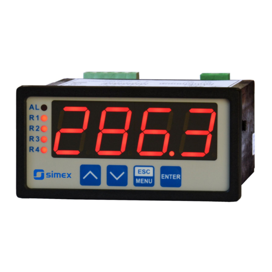
Input type: 0-60/75/100/150 mV
•
4 x 20 mm display
•
Read the user's manual carefully before starting to use the unit or software.
Producer reserves the right to implement changes without prior notice.
2018.12.20
User manual
METER
SRP-94-XC
Assisting the automation
industry since 1986
SRP-94-XC_INSSXEN_v.2.08.001
Advertisement
Table of Contents

Related Manuals for Simex SRP-94-XC


Summary of Contents for Simex SRP-94-XC
- Page 1 Assisting the automation industry since 1986 User manual METER SRP-94-XC Firmware: v.5.18 or higher • Input type: 0-60/75/100/150 mV • 4 x 20 mm display • Read the user's manual carefully before starting to use the unit or software. Producer reserves the right to implement changes without prior notice.
-
Page 2: Table Of Contents
User manual - METER SRP-94-XC CONTENTS 1. BASIC REQUIREMENTS AND USER SAFETY..................3 2. GENERAL CHARACTERISTICS........................4 3. TECHNICAL DATA............................4 4. DEVICE INSTALLATION..........................6 4.1. UNPACKING............................6 4.2. ASSEMBLY............................6 4.3. CONNECTION METHOD........................8 4.4. MAINTENANCE..........................13 5. FRONT PANEL DESCRIPTION........................14 6. PRINCIPLE OF OPERATION........................14 6.1. MEASUREMENT MODE........................14... -
Page 3: Basic Requirements And User Safety
User manual - METER SRP-94-XC Explanation of symbols used in the manual: - This symbol denotes especially important guidelines concerning the installation and operation of the device. Not complying with the guidelines denoted by this symbol may cause an accident, damage or equipment destruction. -
Page 4: General Characteristics
2. GENERAL CHARACTERISTICS The SRP-94-XC meter is equipped with one voltage input 0-60 / 0-75 / 0-100 / 0-150mV. The selection of active input is realised by software, and selected input can be changed at any time. - Page 5 User manual - METER SRP-94-XC Accepted prolonged input overload: 20% Outputs relay: 0, 2 or 4 NO 1A/250V AC (cos j = 1) or OC-type: 0, 2 or 4; 0mA / 30VDC / 100mW sensor power supply: 24V +5%, -10% / max. 100 mA, stabilized active current: range max.
-
Page 6: Device Installation
User manual - METER SRP-94-XC This equipment is not intended for use in residential environments and may not provide adequate protection to radio reception in such environments. 4. DEVICE INSTALLATION The unit has been designed and manufactured in a way assuring a high level of user safety and resistance to interference occurring in a typical industrial environment. - Page 7 User manual - METER SRP-94-XC 67mm (Figure 4.4). 90,5 mm 13 mm 8 mm 8 mm 13 mm max. 5 mm 1 mm 1 mm Figure 4.1. Recommended mounting hole dimensions 92 mm max. 5 mm Figure 4.2. Allowable mounting hole dimensions...
-
Page 8: Connection Method
User manual - METER SRP-94-XC 92 mm 5 mm 12 mm 10 mm Figure 4.3. Installing of brackets, and dimensions of connectors. 115 mm Figure 4.4. Minimum distances when assembly of a number of units 4.3. CONNECTION METHOD Caution - Installation should be conducted by qualified personnel . During installation all available safety requirements should be considered. - Page 9 User manual - METER SRP-94-XC - The power supply network cable diameter must be selected in such a way that in the case of a short circuit of the cable from the side of the unit the cable shall be protected against destruction with an electrical installation fuse.
- Page 10 User manual - METER SRP-94-XC not be run with cables with interference (e.g. circuits controlling relays or contactors). Connections of power supply voltage and measurement signals are executed using the screw connections on the back of the unit’s housing. 6-7 mm Figure 4.5.
- Page 11 User manual - METER SRP-94-XC RS - 485 Power +24V +5%, -10% ACTIVE supply max = 100mA current output DATA+ (optional) DATA- (depending on version) 10 11 12 13 14 15 (optional) (optional) (optional) 0-150mV Figure 4.7. Terminals description (relay outputs, device with current output)
- Page 12 User manual - METER SRP-94-XC 10 11 10 11 Figure 4.9. Examples of suppression circuit connection: a) to relay terminals; b) to the inductive load 10 11 12 13 14 15 FUSE FUSE Depending on version: 85...230...260V AC/DC or 19...24...50V DC; 16...24...35V AC...
-
Page 13: Maintenance
User manual - METER SRP-94-XC 10 11 10 11 Logic controller LED 10 mA voltage input 24 V Figure 4.11. Example of OC-type outputs connection optional ACTIVE current output Logic controller current input 4-20 mA Figure 4.12. Example of current outputs connection (for device with current output only) 4.4. -
Page 14: Front Panel Description
User manual - METER SRP-94-XC 5. FRONT PANEL DESCRIPTION display alarm LED indicator (AL) Thresholds exceeding LED indicators (R) ENTER MENU programming pushbuttons Symbols and functions of push-buttons: Symbol used in the manual: [ESC/MENU] Functions: MENU • Enter to main menu ( press and hold by at least 2 sec.) •... -
Page 15: Detection Of The Peak Values
Configuration of the device (via menu or RS-485 interface) do not stops measures . 6.2. DETECTION OF THE PEAK VALUES The SRP-94-XC controller is equipped with peaks detection function. It can detect a peaks of the input signal and display their values. Presets connected with this function are placed in ”HOLd”... -
Page 16: Control Of The Relay Outputs
User manual - METER SRP-94-XC measure ”timE” ”timE” ”PEA” ”PEA” time real measurement result display value Figure 6.2. Process of peaks detection 6.3. CONTROL OF THE RELAY OUTPUTS The control of the object (measured signal) is realized via relay outputs. Front panel LEDs named „R”... - Page 17 User manual - METER SRP-94-XC state of relay/LED ”SEtP” parameter zone B zone A measure ”HYSt” parameter Figure 6.3. One threshold control of the relay/LED outputs state of relay/LED ”SEtP” or ”SEt2” parameter zone B zone B zone A measure ”HYSt”...
-
Page 18: One Threshold Mode
User manual - METER SRP-94-XC 6.3.1. One threshold mode Figure 6.5 presents the principle of relay outputs operation for one threshold mode, and an example values of other parameters. measured “SEtP” parameter displayed value signal (expected signal value) zone A “HYSt”... -
Page 19: Two Thresholds Mode
User manual - METER SRP-94-XC (when input signal stay in zone A or zone B) are lower than parameters “t on” If t or t or “toFF”, the relay will not change his state (see points A and C, Figure 6.5 a, d, e). -
Page 20: Device Programming
User manual - METER SRP-94-XC Figure 6.6 presents the principle of relay outputs operation for two thresholds mode, and an example values of other parameters. In this mode parameter “SEt2” is accessible in common with “SEtP” , this parameter describes a second threshold of the relay output. The parameters “HYSt”, “modE”, “t on”, “toFF”, “unit”... -
Page 21: Parameters Edition
User manual - METER SRP-94-XC Functions of the buttons while sub-menu and parameters choice: Selection of sub-menu or parameter for editing. Name of selected item (sub- menu or parameter) is displayed. Operation of [ENTER] button depend on present menu position: ENTER •... -
Page 22: Switch Parameters ("List" Type)
User manual - METER SRP-94-XC Press [ENTER] at least 2 seconds to accept the changes, after that question ”Set?” is displayed, and user must to confirm (or cancel) the changes. To conform changes (and story it in EEPROM) press [ENTER] button shortly after ”SEt?” is displayed. To cancel the changes press [ESC] button shortly after ”SEt?”... -
Page 23: Rel1" Menu
User manual - METER SRP-94-XC 7.3.1. “rEL1” menu This menu allows to configure the operation mode of relays and LEDs marked „ R ” (e.g. „ R1 ”). If there are few relay outputs available, then every output has its own configuration menu (e.g. - Page 24 User manual - METER SRP-94-XC - two threshold mode, relay is turned ON when the input value is bigger “out” than “bigger threshold + HYSt” and lower than “lower threshold – HYSt” , and turned on when the input signal is contained in the second zone.
-
Page 25: Beep" Menu
User manual - METER SRP-94-XC If parameter „ AL ” = „ on ”, the relay will be turned on in the critical situations, • even if his parameter “modE” = ”noAC”. 7.3.2. “bEEP” menu This menu contains options connected with acoustic signal : "... - Page 26 User manual - METER SRP-94-XC These parameters describe the values displayed for minimum and maximum input “Lo C” current. For example, if input type is set to 4-20 mA “Lo C” parameter defines the “Hi C” value displayed when input current is equal 4 mA, and “Hi C” parameter defines the value displayed for 20 mA of input current.
-
Page 27: Outp" Menu
User manual - METER SRP-94-XC ”Hi r” - this parameter define the expansion of nominal range in percent. It determine the permissible range of input signal (Figure 7.1). The permissible range allow user to exceed the nominal range of input signal. - Page 28 User manual - METER SRP-94-XC “4-20” - current output enabled with 4 ÷ 20 mA mode, ”modb” - current output controlled via RS-485 interface. ”OUtL” - this parameter determines the input value for which the output current is minimal (0 mA or 4 mA depend of current output mode „ Omod ”).
-
Page 29: Bri" Parameter
User manual - METER SRP-94-XC 7.3.5. ”bri” parameter This parameter allows user to set bright of the LED display, bright can be set to conventional values from 1 to 8. 7.3.6. ”HOLd” menu This menu contains parameters connected with peak detection function. See also full description of the peak detection function in paragraph: DETECTION OF THE PEAK VALUES “modE”... -
Page 30: Rs" Menu
User manual - METER SRP-94-XC The “one-use password” can be used ONE TIME ONLY, it is impossible to use it again! The “one-use password” can be restored by Service Division only. “A r1 ÷ A r4” - this option permits user ( ”on” ) or prohibits ( ”oFF” ) to modify the thresholds of the relays/LEDs R1 ÷... -
Page 31: Edit" Parameter
User manual - METER SRP-94-XC In the most cases parameter ”rESP” should be set to ”Std” (no additional delay). Unfortunately for some third party RS-converters ”rESP” should be adjusted experimentally. Table 7.1 contains most frequently used values. “38.4” “57.6” “115.2”... -
Page 32: Menu Structure
User manual - METER SRP-94-XC 7.4. MENU STRUCTURE Measurement mode Press and hold at least 2 seconds MENU MENU 4-digit user password entering (if it is different from „0000”) 0 _ _ _ ENTER ENTER ENTER Parameter MENU rEL1 SEtP... - Page 33 User manual - METER SRP-94-XC See previous page ENTER ENTER Parameter MENU modE HOLd edition ENTER MENU timE Hdis MENU H r1 H r2 H r3 H r4 HOUt ENTER ENTER Parameter MENU SECu Scod edition ENTER MENU A r1...
-
Page 34: The Alarm Led
User manual - METER SRP-94-XC 8. THE ALARM LED The ALARM LED (AL) is turned on when input signal is out of the permissible input range. See parameters: “tyPE” and “Hi r” in paragraph „InPt” menu. 9. DISPLAYED VALUES CALCULATION The first step to compute the result of measure is the calculation of the normalized result (it means result of 0-1 range). -
Page 35: Linear Characteristic
User manual - METER SRP-94-XC 9.1.1. Linear characteristic The normalized result is converted by fixed coefficients determined by “Lo C” and “Hi C” parameters (when the normalized results is equal 0, then value “Lo C” is displayed, and when the normalized results is equal 1, then value “Hi C” is displayed). Expression presented below... -
Page 36: Square Root Characteristic
User manual - METER SRP-94-XC 9.1.3. Square root characteristic The normalized result is rooted and further conversion is done as for linear characteristic. Conversion is made accordingly with the expression: × "Hi C" −"Lo C" "Lo C" , where W means the displayed value. -
Page 37: Examples Of Calculations
User manual - METER SRP-94-XC Normalized measurement U (for 0-100 mV range) 0,35 5-elements characteristic X (PH) = „70.0.” Y (PH) X = „35.0.” Y (PL) X (PL) = „50.0.” X = „20.0.” Prąd wejściowy [mA] X = „90.0.” X = „100.0.”... - Page 38 User manual - METER SRP-94-XC a) U =37.5 mV and U = 0.375 Accordingly to expression on page 35 for linear characteristic: 0,375 × [1200 -(- 300)] @ 562 and next, the “Lo C” value is added to the result , so the...
- Page 39 User manual - METER SRP-94-XC Example 6: The user defined characteristic Let the input mode = 0-100 mV, and the user selected the 10 segment characteristic. To do this it is necessary to enter X and Y coordinates of 11 points (see Menu ”inPt”).
-
Page 40: The Modbus Protocol Handling
User manual - METER SRP-94-XC Calculated I do not exceeds the output working range (3.8 - 21 mA). b) D = „20.5” According to formula from page 28: = (20.5-10.0) / (20.0-10.0) × 16 mA + 4 mA = 1.05 ·16 + 4 = 20.08 mA Calculated I do not exceeds the output working range (3.8 - 21 mA). - Page 41 User manual - METER SRP-94-XC Register Write Range Register description “tyPE” parameter in “InPt” menu (nominal input range). 0 ÷ 3 0 - 0-60 mV range; 1 - 0-75 mV range; 2 - 0-100 mV range; 3 - 0-150 mV range “CHAr”...
- Page 42 User manual - METER SRP-94-XC Register Write Range Register description “modE” parameter in “rEL1” menu: 0 ÷ 5 0 - “noAC” mode; 1 - “on” mode; 2 - “oFF” mode; 3 - “in” mode; 4 - “out” mode; 5 - “modb” mode “t on”...
- Page 43 User manual - METER SRP-94-XC Register Write Range Register description “modE” parameter in “rEL4” menu: 0 ÷ 5 0 - “noAC” mode; 1 - “on” mode; 2 - “oFF” mode; 3 - “in” mode; 4 - “out” mode; 5 - “modb” mode “t on”...
-
Page 44: Transmission Errors Description
User manual - METER SRP-94-XC Register Write Range Register description “Omod” parameter in “OUtP” menu (current output mode) current output disabled; 1 - current output enabled with 4÷20mA 0 ÷ 2 mode; 2 - current output enabled with 0÷20mA mode;... - Page 45 User manual - METER SRP-94-XC 1. Read of the displayed value (measurement), SRP-94-XC device address = 01h: ADDR FUNC REG H,L COUNT H,L CRC L,H a) The answer (we assume that the measure result is not out of range): ADDR...
- Page 46 User manual - METER SRP-94-XC ADDR FUNC REG H,L DATA H,L CRC L,H 4. Change of baud rate of all devices connected to the net (BROADCAST message). ADDR FUNC REG H,L COUNT H,L CRC L,H DATA H - 0 DATA L - 4, new baud rate 19200 baud Device do not reply to BROADCAST-type messages.
-
Page 47: Default And User's Settings List
User manual - METER SRP-94-XC 11. DEFAULT AND USER'S SETTINGS LIST Desc. Parameter Description Default value User's value page Parameters of relay R1 operation (“rEL1” menu) SEtP Relay R1 threshold 20.0 SEt2 Relay R1 second threshold 40.0 HYSt Hysteresis of relay R1... - Page 48 User manual - METER SRP-94-XC Desc. Parameter Description Default value User's value page t on Turn on delay of relay R4 toFF Turn off delay of relay R4 unit Unit of “t on”, “toFF” parameters of relay R4 Reaction for critical situation of relay R4 Activation of acoustic signal (menu “bEEP”)
- Page 49 User manual - METER SRP-94-XC Desc. Parameter Description Default value User's value page H r2 Source of relay R2, and LED R2 control rEAL H r3 Source of relay R3, and LED R3 control rEAL H r4 Source of relay R4, and LED R4 control...
- Page 50 User manual - METER SRP-94-XC...
- Page 51 User manual - METER SRP-94-XC...
- Page 52 SIMEX Sp. z o.o. ul. Wielopole 11 80-556 Gdańsk Poland tel.: (+48 58) 762-07-77 fax: (+48 58) 762-07-70 http://www.simex.pl e-mail: info@simex.pl...
Need help?
Do you have a question about the SRP-94-XC and is the answer not in the manual?
Questions and answers