Table of Contents
Advertisement
Quick Links
Firmware: v.1.00 or higher
•
Input type: universal
•
Low-cost, no keyboard
•
Read the user's manual carefully before starting to use the unit or software.
Producer reserves the right to implement changes without prior notice.
2014.04.01
User manual
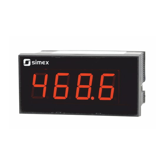
METER
SWE-94-U
Assisting the automation
industry since 1986
SWE-94-U_INSSXEN_v.1.00.002
Advertisement
Table of Contents

Related Manuals for Simex SWE-94-U


Summary of Contents for Simex SWE-94-U
- Page 1 Assisting the automation industry since 1986 User manual METER SWE-94-U Firmware: v.1.00 or higher • Input type: universal • Low-cost, no keyboard • Read the user's manual carefully before starting to use the unit or software. Producer reserves the right to implement changes without prior notice.
-
Page 2: Table Of Contents
User manual - METER SWE-94-U CONTENTS 1. BASIC REQUIREMENTS AND USER SAFETY..................3 2. GENERAL CHARACTERISTICS........................4 3. TECHNICAL DATA............................4 4. DEVICE INSTALLATION..........................7 4.1. UNPACKING............................7 4.2. ASSEMBLY............................7 4.3. CONNECTION METHOD........................9 4.4. MAINTENANCE..........................13 5. DESCRIPTION OF IR REMOTE CONTROLLER AND CONTROL SOFTWARE PUSH-BUTTONS..13 6. -
Page 3: Basic Requirements And User Safety
User manual - METER SWE-94-U Explanation of symbols used in the manual: - This symbol denotes especially important guidelines concerning the installation and operation of the device. Not complying with the guidelines denoted by this symbol may cause an accident, damage or equipment destruction. -
Page 4: General Characteristics
Modbus RTU protocol. Easy assembling, precision and reliability are the basic trumps of SWE-94-U indicators. IR remote controller is not a part of the SWE-94-U and must be ordered separately. 3. TECHNICAL DATA Power supply voltage 230V AC ±10%;... - Page 5 User manual - METER SWE-94-U 0÷5 V, 1÷5 V, 0÷10 V, 2÷10 V Voltage input (10V range) Voltage measurement accuracy ± 0.1% @ 25°C; ± one digit (for 0÷10 V range) Voltage input resistance > 100 kW (while maintaining correct...
- Page 6 User manual - METER SWE-94-U Data memory non-volatile memory, EEPROM type Protection level IP 65 (from front - option, IP 40 - standard) IP 20 (housing and connection clips) Housing type panel Housing material NORYL UL94V-0 Housing dimensions 96 x 48 x 72 mm...
-
Page 7: Device Installation
User manual - METER SWE-94-U 4. DEVICE INSTALLATION The unit has been designed and manufactured in a way assuring a high level of user safety and resistance to interference occurring in a typical industrial environment. In order to take full advantage of these characteristics installation of the unit must be conducted correctly and according to the local regulations. - Page 8 User manual - METER SWE-94-U max. 6 Figure 4.1. Recommended mounting hole dimensions 92,5 max. 6 Figure 4.2. Allowable mounting hole dimensions Figure 4.3. Installing of brackets, and dimensions of connectors.
-
Page 9: Connection Method
User manual - METER SWE-94-U Figure 4.4. Minimum distances when assembly of a number of units 4.3. CONNECTION METHOD Caution - Installation should be conducted by qualified personnel . During installation all available safety requirements should be considered. The fitter is responsible for executing the installation according to this manual, local safety and EMC regulations. - Page 10 User manual - METER SWE-94-U - If the unit is equipped with housing, covers and sealing packing, protecting against water intrusion, pay special attention to their correct tightening or clamping. In the case of any doubt consider using additional preventive measures (covers, roofing, seals, etc.).
- Page 11 User manual - METER SWE-94-U 1 2 3 4 5 6 7 8 9 10 n.c. power DATA- supply DATA+ (depending on version) RS-485 Figure 4.6. Terminals description All connections must be made while power supply is disconnected ! FUSE 230V AC Figure 4.7.
- Page 12 User manual - METER SWE-94-U n.c. n.c. n.c. Pt100 Pt100 Ra, Rc can be different Ra = Rb = Rc Figure 4.8. Connection of RTD sensors: a) 3-wires circuit; b) 2-wires circuit The connection circuit should not be changed while unit is powered. Every change of connection while the unit is powered causes measurement errors by several seconds after change.
-
Page 13: Maintenance
User manual - METER SWE-94-U 24V DC 9 10 Figure 4.11. Connection of voltage converters 4.4. MAINTENANCE The unit does not have any internal replaceable or adjustable components available to the user. Pay attention to the ambient temperature in the room where the unit is operating. -
Page 14: Principle Of Operation
User manual - METER SWE-94-U Symbols and functions of push-buttons: Symbol used in the manual: [ESC/MENU] Functions: MENU • Enter to main menu ( press and hold by at least 2 sec.) • Exit the current level and Enter to previous menu (or measure mode) •... - Page 15 User manual - METER SWE-94-U If the result of measurement exceeds the permissible measurement range, warning ”-Hi-” or ”-Lo-” is displayed rather than input signal, depending on exceeded value (see description of “Lo r” and “Hi r” parameters, paragraph ”inPt” menu). The warning can be effect of measurement circuit malfunction.
-
Page 16: Detection Of The Peak Values
User manual - METER SWE-94-U 6.2. DETECTION OF THE PEAK VALUES The SWE-94-U controller is equipped with peaks detection function. It can detect a peaks of the input signal and display their values. Presets connected with this function are placed in ”HOLd”... -
Page 17: Parameters Edition
User manual - METER SWE-94-U After entering of last digit of the password first menu position will be displayed (if the password is correct) or warning ”Err” in other case. Functions of the buttons while sub-menu and parameters choice: Selection of sub-menu or parameter for editing. Name of selected item (sub- menu or parameter) is displayed. -
Page 18: Switch Parameters ("List" Type)
User manual - METER SWE-94-U Press [ENTER] at least 2 seconds to accept the changes, after that question ”SEt?” is displayed, and user must to confirm (or cancel) the changes. To conform changes (and story it in EEPROM) press [ENTER] button shortly after ”SEt?” is displayed. To cancel the changes press [ESC] button shortly after ”SEt?”... -
Page 19: Inpt" Menu (Common Parameters)
User manual - METER SWE-94-U 7.3.1. “inPt” menu (common parameters) This menu presets the measurement input: “tYPE" - type of the input / sensor. This parameter can be set to values: ”0-20” - current input - range 0..20 mA, ”4-20”... -
Page 20: Inpt" Menu (Parameters Of Current And Voltage Inputs)
User manual - METER SWE-94-U 7.3.3. “inPt” menu (parameters of current and voltage inputs) ”CHAr” - this option presets type of the conversion characteristic, and can be set to: ”Lin” - linear When one of those characteristics is chosen display “Sqr”... - Page 21 User manual - METER SWE-94-U “dELP” - this option allows user to delete any of the points of the user defined characteristic. After selection current number of points of the user defined characteristic is displayed for about approx. 1.5 sec. After that device waits for selection of point being deleted (by [^], [v] buttons).
-
Page 22: Bri" Parameter
User manual - METER SWE-94-U The “Lo r” value can be set from 0 to 99.9%. Parameter “Hi r” determines the upper border of the permissible range accordingly to the expression (for all modes). For example if input is set to “4-20” mode, then upper border is calculated due to expression: = 20 mA + 20 mA ×... -
Page 23: Rs" Menu
User manual - METER SWE-94-U The “one-use password” can be used ONE TIME ONLY, it is impossible to use it again! The “one-use password” can be restored by Service Division only. 7.3.7. ”rS” menu This menu is connected with RS-485 interface, and sets his properties: ”Addr”... -
Page 24: Edit" Parameter
User manual - METER SWE-94-U 7.3.8. ”Edit” paramet er This parameter allows to change the edition mode of numerical parameters: ”dig” - the change to “by digit” mode, ”Slid” - slide change mode. 7.3.9. ”dEFS” parameter This setting allows to restore the factory settings of the device. To get the access to this option special password is required: „5465”, next the device displays acknowledge question... -
Page 25: Menu Structure
User manual - METER SWE-94-U 7.4. MENU STRUCTURE Measurement mode Press and hold at least 2 seconds MENU MENU 4-digit user password entering (if it is different from „0000”) 0 _ _ _ ENTER ENTER ENTER Parameter MENU inPt tYPE... -
Page 26: Over-Current Protection
User manual - METER SWE-94-U 8. OVER-CURRENT PROTECTION The current input of the device is equipped with over-current protection circuit. This circuit protects the standard resistor to damage. Maximum input current is set to 50mA (typical). When temperature of the standard resistor falls, the protection circuit will turn off himself automatically, and the device will measure the input current again. -
Page 27: Linear Characteristic
User manual - METER SWE-94-U 9.1.1. Linear characteristic The normalized result is converted by fixed coefficients determined by “Lo C” and “Hi C” parameters (when the normalized results is equal 0, then value “Lo C” is displayed, and when the normalized results is equal 1, then value “Hi C” is displayed). Expression presented below... -
Page 28: Square Root Characteristic
User manual - METER SWE-94-U 9.1.3. Square root characteristic The normalized result is rooted and further conversion is done as for linear characteristic. Conversion is made accordingly with the expression: × "Hi C" −"Lo C" "Lo C" , where W means the displayed value. -
Page 29: Examples Of Calculations
User manual - METER SWE-94-U Normalized measurement I (for 0-20 mA range) 0,35 5-elements characteristic X (PH) = „70.0.” Y (PH) X = „35.0.” Y (PL) X (PL) = „50.0.” X = „20.0.” Prąd wejściowy [mA] X = „90.0.” X = „100.0.”... - Page 30 User manual - METER SWE-94-U a) I =10 mA and I = 0,375 Accordingly to expression on page 27 for linear characteristic: 0,375 × [1200 -(- 300)] ≅ 562 and next, the “Lo C” value is added to the result , so the displayed value: W ≅...
- Page 31 User manual - METER SWE-94-U Example 6: The user defined characteristic Let the input mode = 4-20 mA, and the user selected the 10 segment characteristic. To do this it is necessary to enter X and Y coordinates of 11 points (see Menu ”inPt”).
-
Page 32: The Modbus Protocol Handling
User manual - METER SWE-94-U 10. THE MODBUS PRO TOCOL HANDLING Transmission parameters: 1 start bit, 8 data bits, 1 or 2 stop bit (2 bits are send, 1 and 2 bits are accepted when receive), no parity control Baud rate:... - Page 33 User manual - METER SWE-94-U Register Write Range Register description 0 ÷ 999 “ Lo r ” parameter in “ InPt ” menu, in 0.1% 0 ÷ 199 “Hi r” parameter in “InPt” menu, in 0.1% “ toFS ” parameter in “ InPt ” menu (shift of measurement scale), -99 ÷...
-
Page 34: Transmission Errors Description
Data byte count in answer frame DATA H,L Data byte (Hi and Lo byte) CRC L,H CRC error check (Hi and Lo byte) 1. Read of the displayed value (measurement), SWE-94-U device address = 01h: ADDR FUNC REG H,L COUNT H,L... - Page 35 User manual - METER SWE-94-U a) The answer (we assume that measurement is not out of range): ADDR FUNC BYTE C DATA H,L CRC L,H DATA H, L - displayed value = 255, no decimal point. Decimal point position can be read from reg. 03h.
- Page 36 User manual - METER SWE-94-U 4. Change of baud rate of all devices connected to the net (BROADCAST message). ADDR FUNC REG H,L COUNT H,L CRC L,H DATA H - 0 DATA L - 4, new baud rate 19200 baud Device do not reply to BROADCAST-type messages.
-
Page 37: Default And User's Settings List
User manual - METER SWE-94-U 11. DEFAULT AND USER'S SETTINGS LIST Desc. Parameter Description Default value User's value page Configuration of measurement input (“inPt” menu) tYPE Input mode „4-20” Conn Connection method „3-in” FiLt Filtering time constant (in seconds) toFS... - Page 38 User manual - METER SWE-94-U...
- Page 39 User manual - METER SWE-94-U...
- Page 40 SIMEX Sp. z o.o. ul. Wielopole 7 80-556 Gdańsk Poland tel.: (+48 58) 762-07-77 fax: (+48 58) 762-07-70 http://www.simex.pl e-mail: info@simex.pl...
Need help?
Do you have a question about the SWE-94-U and is the answer not in the manual?
Questions and answers