Table of Contents
Advertisement
Quick Links
Firmware: v.6.01 or higher
•
Input type: 0/4-20 mA
•
Batching and totalizer function
•
Read the user's manual carefully before starting to use the unit or software.
Producer reserves the right to implement changes without prior notice.
2018.12.20
User manual
FLOW METER
SPP-94
Assisting the automation
industry since 1986
SPP-94_INSSXEN_v.2.10.001
Advertisement
Table of Contents

Related Manuals for Simex SPP-94


Summary of Contents for Simex SPP-94
- Page 1 Assisting the automation industry since 1986 User manual FLOW METER SPP-94 Firmware: v.6.01 or higher • Input type: 0/4-20 mA • Batching and totalizer function • Read the user's manual carefully before starting to use the unit or software. Producer reserves the right to implement changes without prior notice.
-
Page 2: Table Of Contents
User manual - FLOW METER SPP-94 CONTENTS 1. BASIC REQUIREMENTS AND USER SAFETY..................4 2. GENERAL CHARACTERISTICS........................5 3. TECHNICAL DATA............................6 4. DEVICE INSTALLATION..........................8 4.1. UNPACKING............................8 4.2. ASSEMBLY............................9 4.3. CONNECTION METHOD.........................11 4.4. MAINTENANCE..........................18 5. FRONT PANEL DESCRIPTION........................19 6. PRINCIPLE OF OPERATION........................20 6.1. MEASUREMENT MODE........................20... - Page 3 User manual - FLOW METER SPP-94 11. DEFAULT AND USER'S SETTINGS LIST.....................73...
-
Page 4: Basic Requirements And User Safety
User manual - FLOW METER SPP-94 Explanation of symbols used in the manual: - This symbol denotes especially important guidelines concerning the installation and operation of the device. Not complying with the guidelines denoted by this symbol may cause an accident, damage or equipment destruction. -
Page 5: General Characteristics
2. GENERAL CHARACTERISTICS Main task of SPP-94 is measurement of instantaneous flow (flow rate), and counting of total flow (e.g. passage of fluid or gas ), The device can be used as regulator, to control industrial process. -
Page 6: Technical Data
User manual - FLOW METER SPP-94 3. TECHNICAL DATA Power supply voltage 85...230...260V AC/DC; 50 ÷ 60 Hz (separated) (depending on version) or 19... 24 ...50V DC and 16... 24 ...35V AC (separated) External fuse (required) T - type, max. 2 A Power consumption max. - Page 7 User manual - FLOW METER SPP-94 range max. 0 ÷ 11V Active voltage output (optional, for two relays or two OC-type output version only) Load resistance min. 2000 W Instantaneous flow range 0 ÷ 9999, plus decimal point Temperature stability 50 ppm / °C...
-
Page 8: Device Installation
User manual - FLOW METER SPP-94 Safety requirements according to: PN-EN 61010-1 installation category: II pollution degree: 2 voltage in relation to ground: 300V AC insulation resistance: >20MW insulation strength between power supply and input/output terminal: 1min. @ 2300V insulation strength between relays terminal: 1min. -
Page 9: Assembly
User manual - FLOW METER SPP-94 4.2. ASSEMBLY - The unit is designed for mounting inside housings (control panel, switchboard) insuring appropriate protection against surges and interference. Metal housings must be connected to ground in a way that complies with the governing regulations. - Page 10 User manual - FLOW METER SPP-94 92 mm max. 5 mm Figure 4.2. Allowable mounting hole dimensions 92 mm 5 mm 12 mm 10 mm Figure 4.3. Installing of brackets, and dimensions of connectors. 115 mm Figure 4.4. Minimum distances when assembly of a number of units...
-
Page 11: Connection Method
User manual - FLOW METER SPP-94 4.3. CONNECTION METHOD Caution - Installation should be conducted by qualified personnel . During installation all available safety requirements should be considered. The fitter is responsible for executing the installation according to this manual, local safety and EMC regulations. - Page 12 User manual - FLOW METER SPP-94 – Use of screened signal cables is recommended. Signal cable screens should be connected to the earthing only at one of the ends of the screened cable. – In the case of magnetically induced interference the use of twisted couples of signal cables (so-called “spirals”) is recommended.
- Page 13 User manual - FLOW METER SPP-94 Power RS - 485 +24V +5%, -10% (optional) supply max = 100mA DATA+ DATA- (depending on version) 5 6 7 8 9 10 11 12 13 14 15 n.c. n.c. programmable input 0-20mA (optional) (optional) (optional) 4-20mA Figure 4.6.
- Page 14 User manual - FLOW METER SPP-94 Passive, isolated RS - 485 Power Current output +24V +5%, -10% supply 4÷20mA max = 100mA DATA+ (optional) DATA- (depending on version) 5 6 7 8 9 10 11 12 13 14 15 n.c. n.c.
- Page 15 User manual - FLOW METER SPP-94 Passive, isolated Power RS - 485 Current output +24V +5%, -10% supply 4÷20mA max = 100mA DATA+ (optional) DATA- (depending on version) 5 6 7 8 9 10 11 12 13 14 15 n.c. n.c.
- Page 16 User manual - FLOW METER SPP-94 10 11 12 13 14 15 FUSE FUSE Depending on version: 85...230...260V AC/DC or 19...24...50V DC; 16...24...35V AC Figure 4.14. Connection of power supply and relays Contacts of relay outputs are not equipped with spark suppressors. While use the relay outputs for switching of inductive loads (coils, contactors, power relays, electromagnets, motors etc.) it is required...
- Page 17 User manual - FLOW METER SPP-94 10 11 10 11 Logic controller LED 10 mA voltage input 24 V Figure 4.16. Example of OC-type outputs connection ACTIVE current output Logic controller current input 0-20 mA Figure 4.17. Example of active current outputs connection...
-
Page 18: Maintenance
User manual - FLOW METER SPP-94 ACTIVE voltage output Logic controller voltage input 0 - 10V Figure 4.19. Example of active voltage outputs connection (for device with active voltage output only) 4.4. MAINTENANCE The unit does not have any internal replaceable or adjustable components available to the user. -
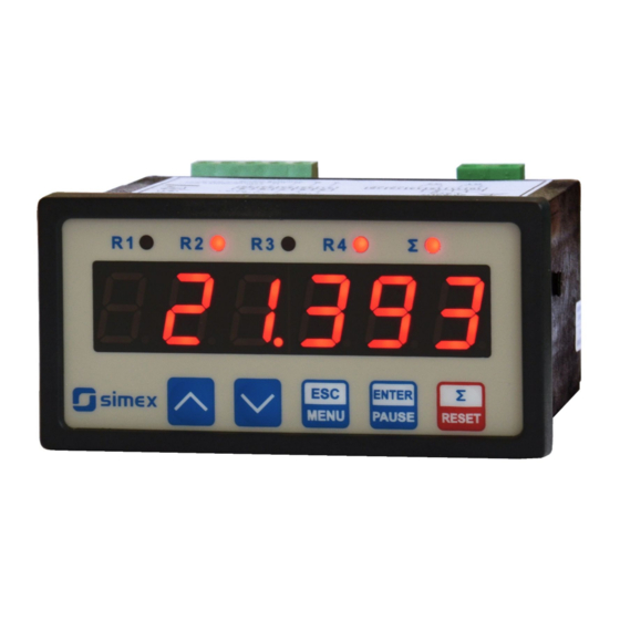
Page 19: Front Panel Description
User manual - FLOW METER SPP-94 5. FRONT PANEL DESCRIPTION Thresholds exceeding LED indicators (R) total flow mode and batching mode LED indicator ( S ) display programming pushbuttons Σ ENTER RESET MENU PAUSE Symbols and functions of push-buttons: Symbol used in the manual: [ESC/MENU]... -
Page 20: Principle Of Operation
User manual - FLOW METER SPP-94 6. PRINCIPLE OF OPERATION After turning the power supply on, device ID and software version are showed on the display, next the controller goes to the measurement mode. 6.1. MEASUREMENT MODE In the measure mode, device displays instantaneous measurement (flow value or time per one unit of flow, depending on „F or P”... - Page 21 User manual - FLOW METER SPP-94 ”Hi r” parameter nominal measurement range 0 mA 20 mA permissible measurement range Figure 6.2. Definitions of measurement ranges in mode 0 ÷ 20 mA – If input current range is strongly overloaded, device can display improper results –...
- Page 22 User manual - FLOW METER SPP-94 Batching counter value is displayed in units defined by parameter “b unit” with resolution defined by parameter “b PrEc” (max 3 digits after decimal point). If batcher counter overflows, warning “bAt ov” is displayed alternatively with maximum counter value. Batching counter can be zeroed using “CLrbAt”...
-
Page 23: Detection Of The Peak Values
(after entering to menu mode counting and controlling is continued in “background”. 6.2. DETECTION OF THE PEAK VALUES The SPP-94 flow meter is equipped with peaks detection function. It can detect a peaks of the input signal and display their values. Presets connected with this function are placed in ”HOLd”... -
Page 24: Control Of The Relay Outputs
User manual - FLOW METER SPP-94 measure ”timE” ”timE” ”PEA” ”PEA” time real measurement result display value Figure 6.4. Process of peaks detection 6.3. CONTROL OF THE RELAY OUTPUTS The control of the object (measured signal) is done due to instantaneous flow value... - Page 25 User manual - FLOW METER SPP-94 state of relay/LED ”SEt P” parameter zone B zone A measure ”HYSt” parameter Figure 6.5. One threshold control of the relay/LED outputs state of relay/LED ”SEt P” or ”SEt P2” parameter zone B zone A...
-
Page 26: One Threshold Mode
User manual - FLOW METER SPP-94 6.3.1. One threshold mode Figure 6.7 presents the principle of relay outputs operation for one threshold mode, and an example values of other parameters. measured “SEt P” parameter displayed value signal (expected signal value) zone A “HYSt”... -
Page 27: Two Thresholds Mode
User manual - FLOW METER SPP-94 If t or t (when input signal stay in zone A or zone B) are lower than parameters “t on” or “t oFF” , the relay will not change its state (see points A and C, Figure 6.7 a, d, e). -
Page 28: Batcher Mode And „Pre R1" Mode
User manual - FLOW METER SPP-94 Figure 6.8 presents the principle of relay outputs operation for two thresholds mode, and an example values of other parameters. In this mode parameter “SEt P2” is accessible in common with “SEt P2” , this parameter describes a second threshold of the relay output. The parameters “HYSt”, “modE”, “t on”, “t oFF”, “unit”... -
Page 29: Use Of The Batcher Counter As A Marker
User manual - FLOW METER SPP-94 Number of batches is counted by another counter (number of batches counter) and stored into the non-volatile memory. To display the value of this counter use [^] or [v] button. After that message ”bAtCnt” and content of number of batches counter are displayed alternatively. -
Page 30: Device Programming
User manual - FLOW METER SPP-94 7. DEVICE PROGRAMMING The device menu allow user to set all parameters connected to operation of measurement input, control modes, critical situations behaviour, communication via RS-485 and access settings. The meaning of the particular parameters is described in paragraph MENU DESCRIPTION. -
Page 31: Parameters Edition
User manual - FLOW METER SPP-94 Functions of the buttons while sub-menu and parameters choice: Selection of sub-menu or parameter for editing. Name of selected item (sub- menu or parameter) is displayed. Operation of [ENTER] button depend on present menu position:... -
Page 32: Switch Parameters ("List" Type)
User manual - FLOW METER SPP-94 7.2.3. Switch parameters (“LIST” type) Switch parameters can be described as a sets of values (a lists) out of which only one of the options available on the list can be selected for the given parameter. Options of switching parameter are selected using keys. - Page 33 User manual - FLOW METER SPP-94 “SourCE” - parameter defining kind of result using to control state of this relay. It can be set to one of three values: “Flo” - relay is controlled due to current flow rate value or stored peak of flow rate (see “Hold”...
- Page 34 User manual - FLOW METER SPP-94 Parameters ”b PrEc” and ”b unit” are available only for relay R1 while batcher mode ( “SourCE” = ” bAt ”) is set. When current flow rate is used to control relays, the unit and precision of the thresholds and hysteresis are defined by parameters “F unit”...
-
Page 35: Beep" Menu
User manual - FLOW METER SPP-94 - two threshold mode, relay is turned OFF when the input value is bigger “Out” than “bigger threshold + HYSt” and lower than “lower threshold – HYSt ”, and turned on when the input signal is contained in the second zone. -
Page 36: Flouu" Menu
User manual - FLOW METER SPP-94 " r1” - if this parameter is set to “ on ”, activation of relay R1 causes by acoustic signal - if this parameter is set to “on”, activation of relay R2 causes by acoustic signal "r2"... - Page 37 User manual - FLOW METER SPP-94 Change of displaying precision can require appropriate correction of relays thresholds and hysteresis. These parameters are not updated automatically, due to settings of “Point” parameter. “F unit” - the unit of volume used for flow rate displaying . It can be set to: (”unit.“ - units, or “1000un”...
- Page 38 User manual - FLOW METER SPP-94 “AddPnt” - this option allow user to add single point to the user defined characteristic. After selection of this option device waits for „X” and „Y” coordinates of new point. Modification of the coordinates is done accordingly to numerical parameters edition.
- Page 39 User manual - FLOW METER SPP-94 " CutoFF" × 20mA CT = for 0 ÷ 20 mA output " CutoFF" × 16mA CT = 4 mA 4 ÷ 20 mA output “Lo r”, ”Hi r” - These parameters define the expansion of nominal range in percent. They determine the permissible range of input currents (Figure7.1).
-
Page 40: Batch" Menu
User manual - FLOW METER SPP-94 If the measurement value do not exceeds permissible measurement range but -Ov- displayed value exceeds range (-99999 ÷ 999999), the warning is displayed ” ” rather than the calculated result. 7.3.4. “bAtCH” menu This menu allows to configure batcher counter displaying mode. -
Page 41: Total" Menu
User manual - FLOW METER SPP-94 “m CLr” - this parameter allows to activate manual zeroing of batcher counter using [ S ] button: ”oFF” - manual zeroing disabled, ”on” - manual zeroing enabled. “A rES” - this parameter allows to activate autoreset function (automatic batcher counter zeroing and start next batching): ”oFF”... -
Page 42: Pr Inp" Menu
User manual - FLOW METER SPP-94 Decimal point position in “Piont” and “t coEF” parameters does not affect on each other. “t unit” - the unit of volume used for total flow counter displaying . It can be set to: (”unit“ - units, or “1000un”... -
Page 43: Init D" Parameter
User manual - FLOW METER SPP-94 “modE” - this parameter allows selection of active level/edge of programmable input. It can be set to one of following: “HI” - executing function while high level on the input “LO” - executing function while low level on the input “LO-HI”... -
Page 44: Outp" Menu
User manual - FLOW METER SPP-94 7.3.9. ”OutP” menu This menu contains parameters of analogue output control. Menu is available if the device is equipped witch analogue output. Analogue output can be controlled depend on both present measured value and peak value (if peak detection is enabled). - Page 45 User manual - FLOW METER SPP-94 “SourCE” - this parameter defines kind of analogue output controlling parameter, and can be set to one of three values: “Flo” - analogue output is controlled due to instantaneous flow (flow rate), “bAt” - analogue output is controlled due to batcher counter result, “tot”...
- Page 46 User manual - FLOW METER SPP-94 “t PrEc” - decimal point position (displaying precision of parameters ”OUt LO” and ”OUt HI”) when analogue output is controlled due to total flow counter result. It can be set to: “ 0“ “...
-
Page 47: Bright" Parameter
User manual - FLOW METER SPP-94 For passive current output: “noCHAn” - current will not change, “22.1” - current will be set to 22.1 mA, “3.4” - current will be set to 3.4 mA, For active voltage output: “noCHAn” - voltage will not change, “11.0”... -
Page 48: Secu" Menu
User manual - FLOW METER SPP-94 “H r1” ÷ “H r4” - relay/LED outputs ( R1÷R4) operation mode: ”rEAL” - relay/LED operates depend on the current value, ”HOLd” - relay/LED operates depend on the peak (drop) value. ”HOUt” - current output operation mode: ”rEAL”... -
Page 49: Edit T" Parameter
User manual - FLOW METER SPP-94 ”mbtimE” - this parameter defines maximal time (sec) between following frames received by the device. If the delay will be greater than the value of ”mbtimE” parameter, the relays and the analogue output which are controlled via RS-485 interface, will set to alert state (see "OUtPUt"... -
Page 50: Units Calculations Examples
User manual - FLOW METER SPP-94 7.4. UNITS CALCULATIONS EXAMPLES During work with the device, there could be a need to recalculate measured value in a unit into another. In the device there is a possibility to do so independently for flow, total flow and batcher using parameters “F coEF”, “t coEF”, “b coEF”... -
Page 51: Units Recalculating Examples
User manual - FLOW METER SPP-94 7.4.1. Units recalculating examples Task: Lets assume that we have a device which woks with sensor scaled in litres. We want, that flow measurement is displayed in US ounces, total flow in hundreds of US gallons and batcher in US gallons. -
Page 52: Menu Structure
User manual - FLOW METER SPP-94 7.5. MENU STRUCTURE Measurement mode MENU Press and hold at least 2 seconds MENU 0 _ _ _ 4-digit user password entering (if it is different from „0000”) ENTER ENTER ENTER MENU SourCE rELAy1... - Page 53 User manual - FLOW METER SPP-94 See previous page ENTER ENTER Parameter MENU vALUE FiLtEr edition ENTER MENU MENU ENTER ENTER Parameter droP MENU OUtPUt OUtmod edition ENTER MENU SourCE OUt LO OUt HI ENTER Parameter MENU briGHt edition b PrEc...
-
Page 54: Over-Current Protection
User manual - FLOW METER SPP-94 8. OVER-CURRENT PROTECTION The input of the device is equipped with over-current protection circuit. This circuit protects the standard resistor to damage. Maximum input current is set to 40mA. When temperature of the standard resistor falls, the protection circuit will turn off himself automatically, and the device will measure the input current again. -
Page 55: Square Characteristic
User manual - FLOW METER SPP-94 Hi CAL Lo CAL Hi CAL Lo CAL Input current [mA] Input current [mA] Figure. 9.1 Normal („Lo CAL” < ”Hi CAL”) and inverted („Lo CAL” > ”Hi CAL”) characteristic 9.1.2. Square characteristic The normalized result is squared and further conversion is done as for linear characteristic. -
Page 56: Square Root Characteristic
User manual - FLOW METER SPP-94 9.1.3. Square root characteristic The normalized result is rooted and further conversion is done as for linear characteristic. Conversion is made accordingly with the expression: × "Hi CAL" −"Lo CAL" "Lo CAL" , where W means the displayed value. -
Page 57: Examples Of Calculations
User manual - FLOW METER SPP-94 Normalized measurement I (for 0-20 mA range) 0,35 5-elements characteristic X (PH) = „70.0.” Y (PH) X = „35.0.” Y (PL) X (PL) = „50.0.” X = „20.0.” Prąd wejściowy [mA] X = „90.0.”... - Page 58 User manual - FLOW METER SPP-94 a) I =10 mA and I = 0,375 Accordingly to expression on page 54 for linear characteristic: 0,375 × [1200 - 300] @ 337 and next, the “Lo CAL” value is added to the result , so the...
- Page 59 User manual - FLOW METER SPP-94 Example 6 : The user defined characteristic Let the input mode = 4-20 mA, and the user selected the 10 segment characteristic. To do this it is necessary to enter X and Y coordinates of 11 points (see Menu ”FLouu”).
- Page 60 /h. Measurement can be done using differential pressure sensor with range 25kPa, and current output signal 4-20mA. The sensor output should be connected to SPP-94 terminals, and proper configuration of input and recalculation is required. Let meter measures with precision 0,1 m /h, parameters of “Flouu”...
-
Page 61: The Modbus Protocol Handling
User manual - FLOW METER SPP-94 10. THE MODBUS PRO TOCOL HANDLING Transmission parameters: 1 start bit, 8 data bits, 1 or 2 stop bit (2 bits are send, 1 and 2 bits are accepted when receive), no parity control... - Page 62 User manual - FLOW METER SPP-94 Register Write Range Register description 0 ÷ 999999 Peak (drop) value (no decimal point) Total flow component expressed in thousands of units e.g.: 0÷FFFFFFFFh 999999999 999 . 999 Total flow component expressed in units e.g.: 0÷999...
- Page 63 User manual - FLOW METER SPP-94 Register Write Range Register description 2078h Device identification code (ID) “bAud” parameter in “rS-485” menu (baud rate); 0 ÷ 7 0 - 1200 baud; 1 - 2400 baud; 2 - 4800 baud; 3 - 9600 baud;...
- Page 64 User manual - FLOW METER SPP-94 Register Write Range Register description 0 ÷ 999999 “SEt P2” parameter in “rELAy1” menu, no decimal point included “SourCE” parameter in “rELAy1” menu (kind of value controlled 0 ÷ 2 relay): 0 - “FLo”; 1 - “bAt”;2 - “tot”;...
- Page 65 User manual - FLOW METER SPP-94 Register Write Range Register description Parameters or relay R3 operation 0 ÷ 999999 “SEt P” parameter in “rELAy3” menu, no decimal point included 0 ÷ 99999 “HySt” parameter in “rELAy3” menu, no decimal point included “modE”...
- Page 66 User manual - FLOW METER SPP-94 Register Write Range Register description 0 ÷ 999999 “SEt P2” parameter in “rELAy4” menu, no decimal point included “SourCE” parameter in “rELAy4” menu (kind of value controlled 0 ÷ 2 relay): 0 - “FLo”; 1 - “bAt”;2 - “tot”;...
- Page 67 User manual - FLOW METER SPP-94 Register Write Range Register description “Lo r” parameter in “OUtPUt” menu for passive current output, 0 ÷ 299 expressed in 0.1% “Hi r” parameter in “OUtPUt” menu for active and passive current 0 ÷ 199 output, expressed in 0.1%...
- Page 68 User manual - FLOW METER SPP-94 Register Write Range Register description “H r2” parameter in “HOLd” menu (the control mode of relay R2 and LED R2) : 0 ÷ 1 0 - control depends on current measurement values; 1 - control depends on peaks (or drops) values;...
- Page 69 User manual - FLOW METER SPP-94 Register Write Range Register description “modE” parameter in “Pr inP” menu (active level/edge of 0 ÷ 3 programmable input): 0 - “HI”; 1 - “LO”; 2 - “LO-HI”; 3 - “HI-LO” Value of “F coEF” parameter in “Flouu” submenu, without 0 ÷...
-
Page 70: Transmission Errors Description
User manual - FLOW METER SPP-94 Register Write Range Register description Calculated batcher component (multiplied “PuLSEL” and “b coEF” values) expressed in thousandths of user units (value 0 ÷ 999 without decimal point): 65535 999 . 999 - it is recommended to read these registers simultaneously – (1,2) and (7,8), (D3h,D4h) in 2-registers frames, and registers (9h,Ah,Bh,Ch) in 4-registers frames. - Page 71 User manual - FLOW METER SPP-94 1. Read of the displayed value (measurement) and status, the device address = 01h: ADDR FUNC REG H,L COUNT H,L CRC L,H The answer : ADDR FUNC BYTE C DATA H1,L1 DATA H2, L2 DATA H3.L3...
- Page 72 User manual - FLOW METER SPP-94 The answer (the same as the message): ADDR FUNC REG H,L DATA H,L CRC L,H 4. Change of baud rate of all devices connected to the net (BROADCAST message). ADDR FUNC REG H,L COUNT H,L...
- Page 73 User manual - FLOW METER SPP-94 11. DEFAULT AND USER'S SETTINGS LIST Desc. Parameter Description Default value User's value page Parameters of relay R1 operation (“rELAy1” menu) SourCE Kind of value controlled relay state SEt P Relay first threshold 20.0...
- Page 74 User manual - FLOW METER SPP-94 Desc. Parameter Description Default value User's value page ALArmS Reaction for critical situation of relay „oFF” Parameters of relay R3 operation (“rELAy3” menu) SourCE Kind of value controlled relay state SEt P Relay first threshold 60.0...
- Page 75 User manual - FLOW METER SPP-94 Desc. Parameter Description Default value User's value page Activation of acoustic signal by relay R2 „oFF” Activation of acoustic signal by relay R3 „oFF” Activation of acoustic signal by relay R4 „oFF” Configuration of current flow display (“FLouu” menu)
- Page 76 User manual - FLOW METER SPP-94 Desc. Parameter Description Default value User's value page modE Active level/edge of programmable input Power on initialization configuration Init d Kind of value displayed after device power on Configuration of data filtration (”FiLtEr” menu)
- Page 77 User manual - FLOW METER SPP-94 Desc. Parameter Description Default value User's value page Precision of “OUt LO” and “OUt HI” parameters t PrEc displaying, while active current output is controlled due to total flow counter value. The unit of “OUt LO” and “OUt HI” parameters...
- Page 78 User manual - FLOW METER SPP-94 Desc. Parameter Description Default value User's value page H r3 Source of relay R3, and LED R3 control „rEAL” H r4 Source of relay R4, and LED R4 control „rEAL” HOUt Source of current output control „rEAL”...
- Page 79 User manual - FLOW METER SPP-94...
- Page 80 SIMEX Sp. z o.o. ul. Wielopole 11 80-556 Gdańsk Poland tel.: (+48 58) 762-07-77 fax: (+48 58) 762-07-70 http://www.simex.pl e-mail: info@simex.pl...
Need help?
Do you have a question about the SPP-94 and is the answer not in the manual?
Questions and answers