Table of Contents
Advertisement
Quick Links
Firmware: v.6.01 or higher
•
Input type: pulse
•
Batching and totalizer function
•
Read the user's manual carefully before starting to use the unit or software.
Producer reserves the right to implement changes without prior notice.
2018.12.20
User manual
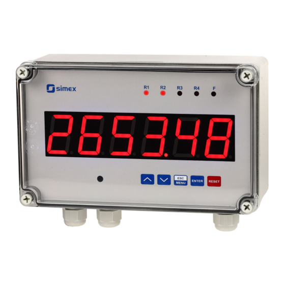
FLOW METER
SPI-638
Assisting the automation
industry since 1986
SPI-638_INSSXEN_v.1.05.001
Advertisement
Table of Contents

Related Manuals for Simex SPI-638


Summary of Contents for Simex SPI-638
- Page 1 Assisting the automation industry since 1986 User manual FLOW METER SPI-638 Firmware: v.6.01 or higher • Input type: pulse • Batching and totalizer function • Read the user's manual carefully before starting to use the unit or software. Producer reserves the right to implement changes without prior notice.
-
Page 2: Table Of Contents
User manual - FLOW METER SPI-638 CONTENTS 1. BASIC REQUIREMENTS AND USER SAFETY..................3 2. GENERAL CHARACTERISTICS........................4 3. TECHNICAL DATA............................5 4. DEVICE INSTALLATION..........................7 4.1. UNPACKING............................7 4.2. ASSEMBLY............................8 4.3. CONNECTION METHOD........................8 4.4. MAINTENANCE..........................16 5. FRONT PANEL DESCRIPTION........................17 6. PRINCIPLE OF OPERATION........................18 6.1. MEASUREMENT MODE........................18... -
Page 3: Basic Requirements And User Safety
User manual - FLOW METER SPI-638 Explanation of symbols used in the manual: - This symbol denotes especially important guidelines concerning the installation and operation of the device. Not complying with the guidelines denoted by this symbol may cause an accident, damage or equipment destruction. -
Page 4: General Characteristics
2. GENERAL CHARACTERISTICS Main task of SPI-638 is measurement of instantaneous flow (flow rate), and counting of total flow (e.g. passage of fluid or gas ), The device can be used as regulator, to control industrial process. -
Page 5: Technical Data
User manual - FLOW METER SPI-638 3. TECHNICAL DATA Power supply voltage 85... 230 ...260V AC/DC; 50 ÷ 60 Hz (separated) (depending on version) or 19...24...50V DC and 16...24...35V AC (separated) External fuse (required) T - type, max. 2 A Power consumption max. - Page 6 User manual - FLOW METER SPI-638 range max. 0 ÷ 11V Active voltage output (optional, for two relays or two OC-type output version only) Load resistance min. 2000 W Instantaneous flow range 0 ÷ 999999, plus decimal point Frequency measurement accuracy ±...
-
Page 7: Device Installation
User manual - FLOW METER SPI-638 Safety requirements according to: PN-EN 61010-1 installation category: II pollution degree: 2 voltage in relation to ground: 300V AC insulation resistance: >20MW insulation strength between power supply and input/output terminal: 1min. @ 2300V insulation strength between relays terminal: 1min. -
Page 8: Assembly
User manual - FLOW METER SPI-638 4.2. ASSEMBLY - Disconnect the power supply prior to starting assembly. - Check the connections are wired correctly prior to switching the unit on. To install device on the wall, a pinholes should be made. Figure 4.1 presents dimensions of the device and distances between holes. - Page 9 User manual - FLOW METER SPI-638 - Wiring must meet appropriate standards and local regulations and laws. - In order to secure against accidental short circuit the connection cables must be terminated with appropriate insulated cable tips. - Tighten the clamping screws. The recommended tightening torque is 0.5 Nm.
- Page 10 User manual - FLOW METER SPI-638 Connections of power supply voltage and measurement signals are executed using the screw connections on the back of the unit’s housing. 6-7 mm Figure 4.2. Method of cable insulation replacing and cable terminals All connections must be made while power supply is disconnected ! Double numeration means, that depending on device version, particular terminal can be marked according to the top or bottom number.
- Page 11 User manual - FLOW METER SPI-638 +24V +5%, -10% Power Imax = 100mA (optional) supply DATA+ - Uo + (optional) DATA- (depending on version) 7 8 9 10 11 12 13 14 15 16 17 18 19 20 Not installed...
- Page 12 User manual - FLOW METER SPI-638 +24V +5%, -10% Power Imax = 100mA (optional) (optional) (optional) (optional) supply DATA+ - Uo + DATA- (depending on version) 13 14 15 16 17 18 19 20 9 10 11 12 pulse input...
- Page 13 User manual - FLOW METER SPI-638 Contacts of relay outputs are not equipped with spark suppressors. While use the relay outputs for switching of inductive loads (coils, contactors, power relays, electromagnets, motors etc.) it is required to use additional suppression circuit (typically capacitor 47nF/ min. 250VAC in series with 100R/5W resistor), connected in parallel to relay terminals or (better) directly on the load.
- Page 14 User manual - FLOW METER SPI-638 Construction of pulse input allows connecting of inductive or optical sensor with common earth (Figure 4.14) or common plus (Figure 4.15), without additional intermediary circuits (sensor with PNP or NPN type output). - Uo +...
- Page 15 User manual - FLOW METER SPI-638 9 10 16 17 Logic controller Voltage input 24 V LED 10 mA R 2k2 9 10 16 17 Figure 4.16. Example of OC-type outputs connection ACTIVE current output (optional) 11 12 Logic controller...
-
Page 16: Maintenance
User manual - FLOW METER SPI-638 Passive, isolated Current output 4÷20mA (optional) 11 12 16 17 Logic controller Isolation loss current input 4-20 mA Figure 4.18. Example of passive current outputs connection (for device with passive current output only) ACTIVE... -
Page 17: Front Panel Description
User manual - FLOW METER SPI-638 5. FRONT PANEL DESCRIPTION Thresholds exceeding alarm LED indicator (F) LED indicators (R) display infrared receiver programming ENTER RESET pushbuttons MENU Symbols and functions of push-buttons: Symbol used in the manual: [ESC/MENU] Functions: MENU •... -
Page 18: Principle Of Operation
User manual - FLOW METER SPI-638 6. PRINCIPLE OF OPERATION After turning the power supply on, device ID and software version are showed on the display, next the controller goes to the measurement mode. 6.1. MEASUREMENT MODE In the measure mode, device displays instantaneous measurement (flow value or time per one unit of flow, depending on „... - Page 19 User manual - FLOW METER SPI-638 Total flow is displayed in units defined by parameter “t unit” with resolution defined by parameter “t PrEc” (max 3 digits after decimal point). If total flow counter overflows, warning “tot ov” is displayed alternatively with maximum counter value. Total flow counter can be zeroed using “Clrtot”...
- Page 20 User manual - FLOW METER SPI-638 If batcher counter value is displayed ( “ S ” LED is pulsing) and counter value • exceeds 6 digits, then decimal point of the most left digit is pulsing. To view most significant digits, it is required to decrease resolution or/and change unit.
-
Page 21: Detection Of The Peak Values
User manual - FLOW METER SPI-638 6.2. DETECTION OF THE PEAK VALUES The SPI-638 flow meter is equipped with peaks detection function. It can detect a peaks of the input signal and display their values. Presets connected with this function are placed in ”HOLd”... -
Page 22: Control Of The Relay Outputs
User manual - FLOW METER SPI-638 6.3. CONTROL OF THE RELAY OUTPUTS The control of the object (measured signal) is done due to instantaneous flow value (current flow rate), total flow counter value or batcher counter value, and is realized via relay outputs. -
Page 23: One Threshold Mode
User manual - FLOW METER SPI-638 The relay outputs and LEDs (named R ) can be controlled depend on both - the current value and the peak value (when peak detection is active, for flow rate only) of the input signal. -
Page 24: Two Thresholds Mode
User manual - FLOW METER SPI-638 (when input signal stay in zone A or zone B) are lower than parameters or t “t on” “t oFF”, the relay will not change his state (see points A and C, Figure 6.5 a, d, e). -
Page 25: Batcher Mode And „Pre R1" Mode
User manual - FLOW METER SPI-638 Figure 6.6 presents the principle of relay outputs operation for two thresholds mode, and an example values of other parameters. In this mode parameter “SEt P2” is accessible in common with “SEt P2” , this parameter describes a second threshold of the relay output. The parameters “HYSt”, “modE”, “t on”, “t oFF”, “unit”... -
Page 26: Use Of The Batcher Counter As A Marker
User manual - FLOW METER SPI-638 Number of batches is counted by another counter (number of batches counter) and stored into the non-volatile memory. To display the value of this counter use [^] or [v] button. After that message ”bAtCnt” and content of number of batches counter are displayed alternatively. -
Page 27: Device Programming
User manual - FLOW METER SPI-638 7. DEVICE PROGRAMMING The device menu allow user to set all parameters connected to operation of measurement input, control modes, critical situations behaviour, communication via RS-485 and access settings. The meaning of the particular parameters is described in paragraph MENU DESCRIPTION. -
Page 28: Parameters Edition
User manual - FLOW METER SPI-638 After about 1 min. since last use of the buttons, device exits the menu mode and returns to the measurement mode (only if no parameters are in editing mode). 7.2. PARAMETERS EDITION To start edition of any parameter user should select name of desired one using [^] [v] buttons and then press [ENTER] . -
Page 29: Menu Description
User manual - FLOW METER SPI-638 Functions of buttons when editing numeric and switching parameters: While editing numeric parameter: • change of current (flashing) digit • slide change of value (acceleration, deceleration, direction change) While editing switch parameter - selection of switch parameter. - Page 30 User manual - FLOW METER SPI-638 “bAt” option is available for relay R1 only. For the rest of relays „PrE r1” option is available. „ PrE r1 ” option means controlling in relation to „ SEt P ” of relay R1 (see CONTROL OF THE RELAY OUTPUTS).
- Page 31 User manual - FLOW METER SPI-638 “t Prec” - decimal point position (displaying precision of the relay thresholds ) when relay is controlled due to total flow counter result. It can be set to: “ 0“ “ 0.0“ “ 0.00“...
-
Page 32: Beep" Menu
User manual - FLOW METER SPI-638 LEDs light when relays are closed, independently of relays' mode. • • When power supply fail, unit do not store relays state selected by RS-485 interface. “t on” - turn on delay time, the relay is turned on with delay equal “t on” if the input value exceeds appropriate border value (defined with threshold and hysteresis), at least “t on”... -
Page 33: Input" Menu
User manual - FLOW METER SPI-638 7.3.3. “inPUt” menu This menu contains options of pulse input configuration: “PulSEL” - flow factor (quantity of pulses per litre). This parameter can be set in range 0.00 - 9999.99 pulses/unit. Value 0.00 is interpreted as 10 000.00 pulses/unit. -
Page 34: Flouu" Menu
User manual - FLOW METER SPI-638 If time delays between successive pulses are longer than “mEAS t” time, then measurement window width is automatically fitted to input frequency. 7.3.4. “FLouu” menu This menu presets the measurement input and allows configuration of current flow rate displaying mode: “F PrEc”... -
Page 35: Batch" Menu
User manual - FLOW METER SPI-638 “F or P” - type of value displayed on the display: “FL vAL” - flow value, “PEriod” - time per one unit of flow. 7.3.5. “bAtCH” menu This menu allows to configure total flow counter displaying mode. - Page 36 User manual - FLOW METER SPI-638 “b unit” - the unit of volume used for batcher counter displaying . It can be set to: (”unit.“ - units, or “1000un” - thousands of user units). Units expressed by “b unit” are conventional, and can be exchanged to any other pair of units e.g.
-
Page 37: Total" Menu
User manual - FLOW METER SPI-638 7.3.6. “totAL” menu This menu allows to configure total flow counter displaying mode. “t PrEc” - decimal point position (precision of total flow counter). It can be set to: “ 0“ “ 0.0“ “ 0.00“... -
Page 38: Bl Inp" Parameter
User manual - FLOW METER SPI-638 “CLrtot” - this option allows zeroing of total flow counter. After selection of this option ask “CLEAr?” is displayed. If user press [ENTER] total flow counter is cleared, else action is cancelled Zeroing of total flow counter is possible via RS-485 interface too. It can be done as write of 0000h to any one of registers referred to total flow counter (09h ÷... -
Page 39: Init D" Parameter
User manual - FLOW METER SPI-638 7.3.8. “ Init d ” parameter This parameter defines type of the value displayed after power on the meter. It is possible to set it to: “Flo” - current flow rate (instantaneous flow), “bAt”... - Page 40 User manual - FLOW METER SPI-638 For active voltage output: ”oFF” - voltage output disabled, ”0-5” - voltage output enabled with 0 ÷ 5V mode, ”1-5” - voltage output enabled with 1 ÷ 5V mode, ”0-10” - voltage output enabled with 0 ÷ 10V mode, “2-10”...
- Page 41 User manual - FLOW METER SPI-638 Parameters ”b PrEc” and ”b unit” are available only if batcher counter is used to control current output ( “SourCE” = ” tot ”). When current flow rate is used to control it, the unit and precision of ”OUt LO” and ”OUt HI” parameters are defined by parameters “F unit”...
-
Page 42: Bright" Parameter
User manual - FLOW METER SPI-638 For passive current output: “noCHAn” - current will not change, “22.1” - current will be set to 22.1 mA, “3.4” - current will be set to 3.4 mA, For active voltage output: “noCHAn” - voltage will not change, “11.0”... -
Page 43: Secu" Menu
User manual - FLOW METER SPI-638 “HdiS” - type of displayed values: ”rEAL” - current value is displayed, ”HOLd” - peak (drop) value is displayed, “H r1” ÷ “H r4” - relay/LED outputs ( R1÷R4) operation mode: ”rEAL” - relay/LED operates depend on the current value, ”HOLd”... -
Page 44: Edit T" Parameter
User manual - FLOW METER SPI-638 The access to registers no 04h i 05h cant be denied by ”mbAccE” parameter (see: LIST OF REGISTERS). ”mbtimE” - this parameter defines maximal time (sec) between following frames received by the device. If the delay will be greater than the value of ”mbtimE” parameter, the relays and the analogue output which are controlled via RS-485 interface, will set to alert state (see "OUtPUt"... -
Page 45: Units Calculations Examples
User manual - FLOW METER SPI-638 7.4. UNITS CALCULATIONS EXAMPLES During work with the device, there could be a need to recalculate measured value in a unit into another. In the device there is a possibility to do so for flow, total flow and batcher using parameters “F coEF”, “t coEF”, “b coEF”... -
Page 46: Units Recalculating Examples
User manual - FLOW METER SPI-638 7.4.1. Units recalculating examples Task: Lets assume that we have a device which woks with sensor scaled in litres. We want, that flow measurement is displayed in US ounces, total flow in hundreds of US gallons and batcher in US gallons. -
Page 47: Menu Structure
User manual - FLOW METER SPI-638 7.5. MENU STRUCTURE Measurement mode MENU Press and hold at least 2 seconds MENU 0 _ _ _ 4-digit user password entering (if it is different from „0000”) ENTER ENTER ENTER MENU SourCE rELAy1... - Page 48 User manual - FLOW METER SPI-638 See previous page ENTER ENTER Parameter MENU FiLtEr vALUE edition ENTER MENU MENU ENTER ENTER droP Parameter MENU OUtPUt OUtmod edition ENTER MENU SourCE OUt LO OUt HI ENTER Parameter MENU briGHt b PrEc...
-
Page 49: Output Value Calculation
User manual - FLOW METER SPI-638 8. OUTPUT VALUE CALCULATION Lets assume that we have active current output and its parameters are: “OUtmod” = “4-20” , “OUt LO” = 100, “OUt HI” = 200, “Lo r” = 5.0, “Hi r” = 5.0 Parameters “Lo r”... -
Page 50: List Of Registers
User manual - FLOW METER SPI-638 9.1. LIST OF REGISTERS Some parameters are located on two registers (higher word in first register, and lower word in next one). After writing of one of them device controls result of their 32-bit value, and if it is necessary corrects value of second register automatically. - Page 51 User manual - FLOW METER SPI-638 Register Write Range Register description “FrEq” parameter in “inPUt” menu (input filter): 0 ÷ 10 0 - 10Hz; 1 - 15Hz; 2 - 20Hz; 3 - 30Hz; 4 - 40Hz; 5 - 50Hz; 6 - 100Hz; 7 - 300Hz; 8 - 1kHz; 9 - 3kHz; 10 - 10kHz “F PrEc”...
- Page 52 User manual - FLOW METER SPI-638 Register Write Range Register description “rESP” parameter in “rS-485” menu (additional response delay); 0 ÷ 5 0 - no additional delay; 1 - ”10c” option; 2 - ”20c” option; 3 - ”50c” option; 4 - ”100c” option; 5 - ”200c” option;...
- Page 53 User manual - FLOW METER SPI-638 Register Write Range Register description “b PrEc” parameter in “rELAy1” menu (precision of thresholds 0 ÷ 3 while relay is controlled due to batcher counter value): 0 - “ 0”; 1 - “ 0.0”; 2 - “ 0.00”; 3 - “0.000”...
- Page 54 User manual - FLOW METER SPI-638 Register Write Range Register description “t oFF” parameter in “rELAy3” menu, expressed in tenth of 0 ÷ 999 seconds or tenth of minutes depend on “unit” parameter “unit” parameter in “rELAy3” menu: 0 ÷ 1 0 - seconds;...
- Page 55 User manual - FLOW METER SPI-638 Register Write Range Register description “t unit” parameter in “rELAy4” menu (the unit of thresholds and 0 ÷ 1 hysteresis while relay is controlled due to total flow counter value): 0 - unit; 1 - 1000un;...
- Page 56 User manual - FLOW METER SPI-638 Register Write Range Register description “OUtmod” parameter in “OUtPUt” menu (active voltege output mode) 0 - voltage disabled; 1 - voltage 0÷5V output output enabled with 0 ÷ 5 mode; 2 - voltage output enabled with 1÷5V mode;...
- Page 57 User manual - FLOW METER SPI-638 Register Write Range Register description “b PrEc” parameter in “bAtCH” (precision of batcher counter 0 ÷ 3 result displaying): 0 - “ 0”; 1 - “ 0.0”; 2 - “ 0.00”; 3 - “0.000”...
- Page 58 User manual - FLOW METER SPI-638 Register Write Range Register description Calculated total flow component (multiplied “PuLSEL” and “t coEF” values) expressed in thousands of user units (value 0 ÷ 999999999 without decimal point): 999999999 999 . 999 Calculated total flow component (multiplied “PuLSEL” and “t coEF”...
-
Page 59: Transmission Errors Description
User manual - FLOW METER SPI-638 9.2. TRANSMISSION ERRORS DESCRIPTION If an error occurs while write or read of single register, then the device sends an error code according to Modbus RTU specifications (example message no 5). Error codes: 01h - illegal function (only functions 03h, 06h and 10h are available),... - Page 60 User manual - FLOW METER SPI-638 2. Read of device ID code ADDR FUNC REG H,L COUNT H,L CRC L,H The answer: ADDR FUNC BYTE C DATA H,L CRC L,H DATA - identification code (2046h) 3. Change of the device address from 1 to 2 (write to reg. 20h)
- Page 61 User manual - FLOW METER SPI-638 Device response ( with exception code 03h): ADDR FUNC CRC L,H There is no full implementation of the Modbus Protocol in the device. The functions presented above are available only.
-
Page 62: Default And User's Settings List
User manual - FLOW METER SPI-638 10. DEFAULT AND USER'S SETTINGS LIST Desc. Parameter Description Default value User's value page Parameters of relay R1 operation (“rELAy1” menu) SourCE Kind of value controlled relay state SEt P Relay first threshold 20.0... - Page 63 User manual - FLOW METER SPI-638 Desc. Parameter Description Default value User's value page Parameters of relay R3 operation (“rELAy3” menu) SourCE Kind of value controlled relay state SEt P Relay first threshold 60.0 SEt P2 Relay second threshold 70.0...
- Page 64 User manual - FLOW METER SPI-638 Desc. Parameter Description Default value User's value page Activation of acoustic signal by relay R4 „oFF” Configuration of measurement input (”inPUt” menu) PULSEL Flow sensor factor (quantity of pulses per unit) 1.00 FrEq Maximum input frequency...
- Page 65 User manual - FLOW METER SPI-638 Desc. Parameter Description Default value User's value page Configuration of data filtration (”FiLtEr” menu) vALUE Filtering ratio Measured value change causing of temporal droP 20.0 (%) filtering deactivation Active current output configuration (“OUtPUt” menu)
- Page 66 User manual - FLOW METER SPI-638 Desc. Parameter Description Default value User's value page The unit of “OUt LO” and “OUt HI” parameters t unit unit displaying, while active current output is controlled due to total flow counter value. Lo r Extension of the bottom of the nominal output range 5.0 (%)
- Page 67 User manual - FLOW METER SPI-638 Desc. Parameter Description Default value User's value page HOUt Source of current output control „rEAL” Settings of access to the configuration parameters (“SECU” menu) Permission to changes of relay R1 threshold Acc r1 without of the user password knowledge...
- Page 68 SIMEX Sp. z o.o. ul. Wielopole 11 80-556 Gdańsk Poland tel.: (+48 58) 762-07-77 fax: (+48 58) 762-07-70 http://www.simex.pl e-mail: info@simex.pl...
Need help?
Do you have a question about the SPI-638 and is the answer not in the manual?
Questions and answers