Table of Contents
Advertisement
Quick Links
Input type: load cells
•
Calibration using theoretical characteristic or real load
•
Read the user's manual carefully before starting to use the unit or software.
Producer reserves the right to implement changes without prior notice.
2018.12.18
User manual
WEIGHT METER
SWI-94
Assisting the automation
industry since 1986
SWI-94_INSSXEN_v.2.12.001
Advertisement
Table of Contents

Related Manuals for Simex SWI-94


Summary of Contents for Simex SWI-94
- Page 1 Assisting the automation industry since 1986 User manual WEIGHT METER SWI-94 Input type: load cells • Calibration using theoretical characteristic or real load • Read the user's manual carefully before starting to use the unit or software. Producer reserves the right to implement changes without prior notice.
-
Page 2: Table Of Contents
User manual - WEIGHT METER SWI-94 CONTENTS 1. BASIC REQUIREMENTS AND USER SAFETY..................3 2. GENERAL CHARACTERISTICS.......................4 3. TECHNICAL DATA............................4 4. DEVICE INSTALLATION...........................6 4.1. UNPACKING.............................7 4.2. ASSEMBLY............................7 4.3. CONNECTION METHOD.......................11 4.4. MAINTENANCE..........................20 5. FRONT PANEL DESCRIPTION ......................21 6. PRINCIPLE OF OPERATION........................22 6.1. -
Page 3: Basic Requirements And User Safety
User manual - WEIGHT METER SWI-94 Explanation of symbols used in the manual: - This symbol denotes especially important guidelines concerning the installation and operation of the device. Not complying with the guidelines denoted by this symbol may cause an accident, damage or equipment destruction. -
Page 4: General Characteristics
User manual - WEIGHT METER SWI-94 - Do not use the unit in areas where there is risk of explosions. - Do not use the unit in areas with significant temperature variations, exposure to condensation or ice. - Do not use the unit in areas exposed to direct sunlight. - Page 5 User manual - WEIGHT METER SWI-94 separated Programmable input Low level 0V ÷ 1V High level 10V ÷ 30V (about 5.5mA @ 24V) 24V +5%, -10% / max. 100 mA, stabilized Sensor power supply output Relay output 0 or 2 NO 1A/250V AC (cos j = 1) 0 or 2;...
-
Page 6: Device Installation
User manual - WEIGHT METER SWI-94 Housing type panel Housing material NORYL - GFN2S E1 Housing dimensions 96 x 48 x 100 mm Mounting hole 90.5 x 43 mm Assembly depth 102 mm Panel thickness max. 5 mm Operating temperature 0°C to +50°C... -
Page 7: Unpacking
User manual - WEIGHT METER SWI-94 4.1. UNPACKING After removing the unit from the protective packaging, check for transportation damage. Any transportation damage must be immediately reported to the carrier. Also, write down the unit serial number on the housing and report the damage to the manufacturer. - Page 8 User manual - WEIGHT METER SWI-94 92 mm max. 5 mm Figure 4.2. Allowable mounting hole dimensions 92 mm 5 mm 12 mm 10 mm Figure 4.3. Installing of brackets, and dimensions of connectors. 115 mm Figure 4.4. Minimum distances when assembly of a number of units...
- Page 9 User manual - WEIGHT METER SWI-94 - The unit is designed for mounting inside housings (control panel, switchboard) insuring appropriate protection against surges and interference. Metal housings must be connected to ground in a way that complies with the governing regulations.
- Page 10 User manual - WEIGHT METER SWI-94 92 mm max. 5 mm Figure 4.6. Allowable mounting hole dimensions 92 mm 5 mm 12 mm 10 mm Figure 4.7. Installing of brackets, and dimensions of connectors. 115 mm Figure 4.8. Minimum distances when assembly of a number of units...
-
Page 11: Connection Method
User manual - WEIGHT METER SWI-94 4.3. CONNECTION METHOD Caution - Installation should be conducted by qualified personnel . During installation all available safety requirements should be considered. The fitter is responsible for executing the installation according to this manual, local safety and EMC regulations. - Page 12 User manual - WEIGHT METER SWI-94 – Use of screened signal cables is recommended. Signal cable screens should be connected to the earthing only at one of the ends of the screened cable. – In the case of magnetically induced interference the use of twisted couples of signal cables (so-called “spirals”) is recommended.
- Page 13 User manual - WEIGHT METER SWI-94 Notes related to connection of strain bridges: - Installation should be made according to local safety and electromagnetic compatibility regulations. While installation pay special attention to: - use of shielded wires, - shield of wires should be connected with metal housing using a conductive glands or metal clamp to ensure proper electrical contact.
- Page 14 User manual - WEIGHT METER SWI-94 +24V +5%, -10% Power RS - 485 ACTIVE max = 100mA voltage output supply DATA+ (optional) (depending on version) DATA- 5 6 7 8 9 10 11 12 13 14 15 30 31 32 33 34...
- Page 15 User manual - WEIGHT METER SWI-94 +24V +5%, -10% Power RS - 485 ACTIVE max = 100mA voltage output supply DATA+ (optional) (depending on version) DATA- 5 6 7 8 9 10 11 12 13 14 15 30 31 32 33 34...
- Page 16 User manual - WEIGHT METER SWI-94 10 11 10 11 Figure 4.17. Examples of suppression circuit connection: a) to relay terminals; b) to the inductive load 10 11 10 11 Logic controller LED 10 mA voltage input 24 V Figure 4.18. Example of OC-type outputs connection...
- Page 17 User manual - WEIGHT METER SWI-94 PASSIVE current output Logic controller Isolation loss current input 4-20 mA Figure 4.20. Example of passive current outputs connection (for device with passive current output only) ACTIVE voltage output Logic controller voltage input 0 - 10V Figure 4.21.
- Page 18 User manual - WEIGHT METER SWI-94 METAL HOUSING NOTE: Shield and terminal No. 7 must be connected to PE wire. 30 31 32 33 34 35 EXC- load cell transducer SENSE- SIGN- SIGN+ SENSE+ EXC+ SHIELD Rys. 4.22. Example of 6-wire load cell connection.
- Page 19 User manual - WEIGHT METER SWI-94 EXC+ load cell EXC+ EXC+ EXC+ transducer SENSE+ SENSE+ SENSE+ EXC- EXC- EXC- EXC- SENSE- SENSE- SENSE- SIGN+ SIGN+ SIGN+ SIGN+ SIGN- SIGN- SIGN- SIGN- SHIELD SHIELD SHIELD EXC+ load cell EXC+ transducer SENSE+...
-
Page 20: Maintenance
User manual - WEIGHT METER SWI-94 EXC+ load cell EXC+ EXC+ EXC+ SENSE+ transducer SENSE+ SENSE+ SENSE+ EXC- EXC- EXC- EXC- SENSE- SENSE- SENSE - SENSE- SIGN+ SIGN+ SIGN+ SIGN+ SIGN- SIGN- SIGN- SIGN- SHIELD SHIELD SHIELD EXC+ load cell... -
Page 21: Front Panel Description
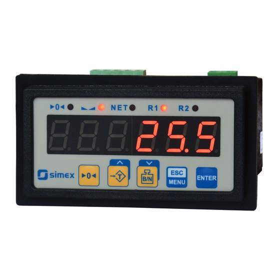
User manual - WEIGHT METER SWI-94 5. FRONT PANEL DESCRIPTION stable measurement nett value LED indicator (NET) LED indicator (><) Thresholds exceeding LED indicators (R) zero value LED indicator (>0<-) programming display pushbuttons ENTER MENU Symbols and functions of push-buttons:... -
Page 22: Principle Of Operation
User manual - WEIGHT METER SWI-94 6. PRINCIPLE OF OPERATION After turning the power supply on, device ID and software version are showed on the display, next the controller goes to the measurement mode. 6.1. MEASUREMENT MODE While device is in measurement mode LED display shows gross or net weight. Net weight presentation mode is signalized by LED marked „... -
Page 23: Detection Of The Peak Values
User manual - WEIGHT METER SWI-94 6.2. DETECTION OF THE PEAK VALUES The SWI-94 weight meter is equipped with peaks detection function. It can detect a peaks of the input signal and display their values. Presets connected with this function are placed in ”HOLd”... -
Page 24: Control Of The Relay Outputs
User manual - WEIGHT METER SWI-94 6.3. CONTROL OF THE RELAY OUTPUTS The control of the object (measured signal) is done due to gross or nett value “SourCE” (depending on parameter), and is realized via relay outputs. Front panel LEDs named „R”... -
Page 25: One Threshold Mode
User manual - WEIGHT METER SWI-94 6.3.1. One threshold mode Figure 6.4 presents the principle of relay outputs operation for one threshold mode, and an example values of other parameters. measured “SEt P” parameter displayed value signal (expected signal value) zone A “HYSt”... -
Page 26: Two Thresholds Mode
User manual - WEIGHT METER SWI-94 If t or t (when input signal stay in zone A or zone B) are lower than parameters “t on” or “t oFF” , the relay will not change his state (see points A and C, graph: a, d, e). -
Page 27: Device Programming
User manual - WEIGHT METER SWI-94 Figure 6.5 presents the principle of relay outputs operation for two thresholds mode, and an example values of other parameters. In this mode parameter “SEt P2” is accessible in common with “SEt P2” , this parameter describes a second threshold of the relay output. The parameters “HYSt”, “modE”, “t on”, “t oFF”, “unit”... -
Page 28: Parameters Edition
User manual - WEIGHT METER SWI-94 Functions of the buttons while sub-menu and parameters choice: Selection of sub-menu or parameter for editing. Name of selected item (sub- menu or parameter) is displayed. Operation of [ENTER] button depend on present menu position: ENTER •... -
Page 29: Switch Parameters ("List" Type)
User manual - WEIGHT METER SWI-94 7.2.3. Switch parameters (“LIST” type) Switch parameters can be described as a sets of values (a lists) out of which only one of the options available on the list can be selected for the given parameter. Options of switching parameter are selected using keys. - Page 30 User manual - WEIGHT METER SWI-94 “SourCE” - parameter defining kind of result using to control state of this relay. It can be set to one of two values: “GroSS” - relay is controlled due to gross value of weight, “...
- Page 31 User manual - WEIGHT METER SWI-94 Mode: Relay switches on when: Relay switches off when: w Pr, for h=0 w < Pr, for h=0 „on” for h ≠ 0 w Pr - h, for h ≠ 0 w Pr + h, w <...
-
Page 32: Beeper" Menu
User manual - WEIGHT METER SWI-94 “ALArmS” - this parameter defines the relay reaction when some critical situations occurs: “noCHAn” - relay do not change his state, “on” - relay will be turned on, “oFF” - relay will be turned off. - Page 33 User manual - WEIGHT METER SWI-94 ”C tYPE” - calibration type. Possible values: “dAtA” - theoretical calibration („Data Sheet” type calibration) according to data sheet of load cell transducers (strain bridges), “rEAL” - dead weight calibration (entry of values for certain known loads).
-
Page 34: Output" Menu
User manual - WEIGHT METER SWI-94 changes of input signal (weight) high value of „ FiLtEr ” can cause degradation of measurement precision. ”S tESt” - this function allows to view transducer signal value expressed in mV/V. Procedure of theoretical calibration Set parameter „C tYPE”... - Page 35 User manual - WEIGHT METER SWI-94 For active voltage output: ”oFF” - voltage output disabled, ”0-5” - voltage output enabled with 0 ÷ 5V mode, ”1-5” - voltage output enabled with 1 ÷ 5V mode, ”0-10” - voltage output enabled with 0 ÷ 10V mode, “2-10”...
-
Page 36: Button" Menu
User manual - WEIGHT METER SWI-94 In example on page 42 the procedure of the analogue outputs determining is presented in details. “ AL ” - this parameter determines the behaviour of analogue output if any critical situation occurs. According to version of the device, this parameter can be set: For active current output: “noCH”... -
Page 37: Pr Inp" Parameter
User manual - WEIGHT METER SWI-94 ”b nett” - enable of presentation mode switching ( gross/net) - button[ B/N ]: “oFF” - disabled, “on” - enabled. 7.3.6. ” Pr inP ” parameter This parameter allows enabling of function realised by programmable input. -
Page 38: Secur" Menu
User manual - WEIGHT METER SWI-94 7.3.9. ”SECUr” menu This menu contains presets connected with availability of other parameters: ”SEtCod” - user password (4-digits number). If this parameter is set at value “0000” , user password is turned off. If the user do not remember his password, the access to the menu is possible by the “one-use password”. -
Page 39: Edit T" Parameter
User manual - WEIGHT METER SWI-94 ”Std” - answer as quick as possible, no additional delay ” 10c” ” 20c” - answer delayed of 10, 20, 50, 100 of 200 chars respectively, where ” 50c” one character time depends on selected baud rate ”100c”... -
Page 40: Menu Structure
User manual - WEIGHT METER SWI-94 7.4. MENU STRUCTURE Measurement mode Press and hold at least 2 seconds MENU MENU 4-digit user password entering (if it is different from „0000”) 0 _ _ _ ENTER ENTER ENTER Parameter MENU SourCE... - Page 41 User manual - WEIGHT METER SWI-94 See previous page ENTER Parameter MENU Pr inP edition ENTER MENU ENTER ENTER Parameter MENU HOLd modE edition ENTER MENU ENTER Parameter MENU briGHt edition ENTER timE MENU MENU ENTER ENTER Parameter H disP...
-
Page 42: Output Value Calculation
User manual - WEIGHT METER SWI-94 8. OUTPUT VALUE CALCULATION Lets assume that we have active current output and its parameters are: “modE” = “on”, “OUt LO” = 100, “OUt HI” = 200, “Lo r” = 5.0, “Hi r” = 5.0 Parameters “Lo r”... -
Page 43: The Modbus Protocol Handling
User manual - WEIGHT METER SWI-94 10. THE MODBUS PRO TOCOL HANDLING Transmission parameters: 1 start bit, 8 data bits, 1 or 2 stop bit (2 bits are send, 1 and 2 bits are accepted when receive), no parity control... - Page 44 User manual - WEIGHT METER SWI-94 Register Write Range Register description -99999 ÷ Gross measurement value (no decimal point) 999999 -99999 ÷ Nett measurement value (no decimal point). Writing a „0” value 999999 causes the execution of the tare function.
- Page 45 User manual - WEIGHT METER SWI-94 Register Write Range Register description 0 ÷ 1 “r1” parameter in “bEEP” menu: 0 - off; 1 - on 0 ÷ 1 “r2” parameter in “bEEP” menu: 0 - off; 1 - on “briGHt” parameter (display brightness);...
- Page 46 User manual - WEIGHT METER SWI-94 Register Write Range Register description “ALArmS” parameter in “rELAy2” menu: 0 ÷ 2 0 - no changes; 1 - on; 2 - off -99999 ÷ “SEt P2” parameter in “rELAy2” menu, no decimal point included 999999 “SourCE”...
- Page 47 User manual - WEIGHT METER SWI-94 Register Write Range Register description “Omod” parameter in “OUtP” menu (passive current output mode) 0 ÷ 2 current output disabled; 1 - current output enabled with 4÷20mA mode; 2 - current output controlled via RS-485 interface “Omod”...
-
Page 48: Transmission Errors Description
User manual - WEIGHT METER SWI-94 10.2. TRANSMISSION ERRORS DESCRIPTION If an error occurs while write or read of single register, then the device sends an error code (according to Modbus RTU specifications). Error codes: 01h - illegal function (only functions 03h, 06h and 10h are available),... - Page 49 User manual - WEIGHT METER SWI-94 b) The answer (if an error occur): ADDR FUNC ERROR CRC L,H ERROR - error code = 40h, bottom border of the measurement range is exceeded 2. Read of device ID code ADDR FUNC...
- Page 50 User manual - WEIGHT METER SWI-94 5. Try to write improper data to register (register 04h): ADDR FUNC REG H,L DATA H,L CRC L,H DATA H, L written value (10h = 16) out of allowable range (0 ÷ 2) Device response ( with exception code 03h):...
-
Page 51: Default And User's Settings List
User manual - WEIGHT METER SWI-94 11. DEFAULT AND USER'S SETTINGS LIST Desc. Parameter Description Default value User's value page Parameters of relay R1 operation (“rELAy1” menu) SourCE Kind of value controlled relay state GroSS SEt P Relay first threshold 20.0... - Page 52 User manual - WEIGHT METER SWI-94 Desc. Parameter Description Default value User's value page Z oFFS Zero Offset parameter FiLtEr Measurements filtration rate Active current output configuration (“OUtP” menu) Omod Active current output mode 0-20 (mA) OUtL Display value for 0 mA or 4 mA current output...
- Page 53 User manual - WEIGHT METER SWI-94 Desc. Parameter Description Default value User's value page Maximum time of peak displaying timE 0.0 (sec.) H diSP The type of displayed value rEAL H rEL1 Source of relay R1, and LED R1 control...
- Page 54 User manual - WEIGHT METER SWI-94...
- Page 55 User manual - WEIGHT METER SWI-94...
- Page 56 SIMEX Sp. z o.o. ul. Wielopole 11 80-556 Gdańsk Poland tel.: (+48 58) 762-07-77 fax: (+48 58) 762-07-70 http://www.simex.pl e-mail: info@simex.pl...
Need help?
Do you have a question about the SWI-94 and is the answer not in the manual?
Questions and answers