Table of Contents
Advertisement
Quick Links
Firmware: v.1.01 or higher
•
Input type: universal
•
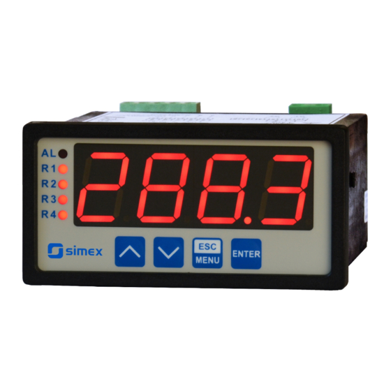
4 x 20 mm display
•
Read the user's manual carefully before starting to use the unit or software.
Producer reserves the right to implement changes without prior notice.
2013.12.09
User manual
METER
SUR-94
Assisting the automation
industry since 1986
SUR-94_INSSXEN_v.1.04.001
Advertisement
Table of Contents

Related Manuals for Simex SUR-94


Summary of Contents for Simex SUR-94
- Page 1 Assisting the automation industry since 1986 User manual METER SUR-94 Firmware: v.1.01 or higher • Input type: universal • 4 x 20 mm display • Read the user's manual carefully before starting to use the unit or software. Producer reserves the right to implement changes without prior notice.
-
Page 2: Table Of Contents
User manual - METER SUR-94 CONTENTS 1. BASIC REQUIREMENTS AND USER SAFETY..................3 2. GENERAL CHARACTERISTICS........................4 3. TECHNICAL DATA............................4 4. DEVICE INSTALLATION..........................7 4.1. UNPACKING............................7 4.2. ASSEMBLY............................8 4.3. CONNECTION METHOD.........................10 4.4. MAINTENANCE..........................18 5. FRONT PANEL DESCRIPTION........................18 6. PRINCIPLE OF OPERATION........................19 6.1. MEASUREMENT MODE........................19... -
Page 3: Basic Requirements And User Safety
User manual - METER SUR-94 Explanation of symbols used in the manual: - This symbol denotes especially important guidelines concerning the installation and operation of the device. Not complying with the guidelines denoted by this symbol may cause an accident, damage or equipment destruction. -
Page 4: General Characteristics
94 with two relays (or OC type) outputs can be equipped with active current output, passive isolated current output or active voltage output. Device SUR-94 is equipped with RS-485 / Modbus RTU communication interface and sensor supply output. The meter can be ordered in two power supply versions. - Page 5 User manual - METER SUR-94 0÷5 V, 1÷5 V, 0÷10 V, 2÷10 V Voltage input (10V range) Voltage measurement accuracy ± 0.1% @ 25°C; ± one digit (for 0÷10 V range) Voltage input resistance > 100 kW (while maintaining correct...
- Page 6 User manual - METER SUR-94 range max. 0 ÷ 24 mA Active current output (optional, for two relays or two OC-type output version only) Load resistance max. 700 Ω range max. 2.8 ÷ 24 mA Passive isolated current output (optional, for two relays or two...
-
Page 7: Device Installation
User manual - METER SUR-94 Humidity 5 to 90% no condensation Altitude up to 2000 meters above sea level Screws tightening max. torque 0,5 Nm Max. connection leads cross section 2,5 mm Safety requirements according to: PN-EN 61010-1 installation category: II... -
Page 8: Assembly
User manual - METER SUR-94 4.2. ASSEMBLY - The unit is designed for mounting inside housings (control panel, switchboard) insuring appropriate protection against surges and interference. Metal housings must be connected to ground in a way that complies with the governing regulations. - Page 9 User manual - METER SUR-94 92 mm max. 5 mm Figure 4.2. Allowable mounting hole dimensions 92 mm 5 mm 12 mm 10 mm Figure 4.3. Installing of brackets, and dimensions of connectors. 115 mm Figure 4.4. Minimum distances when assembly of a number of units...
-
Page 10: Connection Method
User manual - METER SUR-94 4.3. CONNECTION METHOD Caution - Installation should be conducted by qualified personnel . During installation all available safety requirements should be considered. The fitter is responsible for executing the installation according to this manual, local safety and EMC regulations. - Page 11 User manual - METER SUR-94 Use of screened signal cables is recommended. Signal cable screens should be – connected to the earthing only at one of the ends of the screened cable. In the case of magnetically induced interference the use of twisted pair of signal cables is –...
- Page 12 User manual - METER SUR-94 RS - 485 Power +24V +5%, -10% supply max = 100mA DATA+ (optional) DATA- (depending on version) 5 6 7 8 9 10 11 12 13 14 15 31 32 33 34 35 (optional) (optional) (optional) OC1 ÷...
- Page 13 User manual - METER SUR-94 Passive, isolated RS - 485 Power Current output +24V +5%, -10% supply 4÷20mA max = 100mA DATA+ (optional) DATA- (depending on version) 5 6 7 8 9 10 11 12 13 14 15 31 32 33 34 35 n.c.
- Page 14 User manual - METER SUR-94 Power RS - 485 ACTIVE +24V +5%, -10% supply voltage output max = 100mA DATA+ (optional) DATA- (depending on version) 5 6 7 8 9 10 11 12 13 14 15 31 32 33 34 35 n.c.
- Page 15 User manual - METER SUR-94 internally connected 24V DC 31 32 33 34 35 31 32 33 34 35 Figure 4.16. Connection of voltage converters Temperature sensor can be connected to the device in typical 4-wire circuit (Figure 4.17a) or 3-wire circuit ( Figure 4.17b ).
- Page 16 User manual - METER SUR-94 10 11 12 13 14 15 FUSE FUSE Depending on version: 85...230...260V AC/DC or 19...24...50V DC; 16...24...35V AC Figure 4.18. Connection of power supply and relays Contacts of relay outputs are not equipped with spark suppressors. While use the relay outputs for switching of inductive loads (coils, contactors, power relays, electromagnets, motors etc.) it is required...
- Page 17 User manual - METER SUR-94 10 11 10 11 Logic controller LED 10 mA voltage input 24 V Figure 4.20. Example of OC-type outputs connection ACTIVE current output Logic controller current input 0-20 mA Figure 4.21. Example of active current outputs connection...
-
Page 18: Maintenance
User manual - METER SUR-94 ACTIVE voltage output Logic controller voltage input 0 - 10V Figure 4.23. Example of active voltage outputs connection (for device with active voltage output only) 4.4. MAINTENANCE The unit does not have any internal replaceable or adjustable components available to the user. -
Page 19: Principle Of Operation
User manual - METER SUR-94 Symbols and functions of push-buttons: Symbol used in the manual: [ESC/MENU] Functions: MENU • Enter to main menu ( press and hold by at least 2 sec.) • Exit the current level and Enter to previous menu (or measure mode) •... - Page 20 User manual - METER SUR-94 description of “Lo r” and “Hi r” parameters, paragraph ”inPt” menu). The warning can be effect of measurement circuit malfunction. In that case “-Lo-” means shortcut and “-Hi-” means break of measurement circuit. If sensor failure will be detected (e.g. broken wires), then ”S.Err”...
-
Page 21: Detection Of The Peak Values
User manual - METER SUR-94 6.2. DETECTION OF THE PEAK VALUES The SUR-94 controller is equipped with peaks detection function. It can detect a peaks of the input signal and display their values. Presets connected with this function are placed in ”HOLd”... - Page 22 User manual - METER SUR-94 state of relay/LED ”SEtP” parameter zone B zone A measure ”HYSt” parameter Figure 6.5. One threshold control of the relay/LED outputs state of relay/LED ”SEtP” or ”SEt2” parameter zone B zone A zone B measure ”HYSt”...
-
Page 23: One Threshold Mode
User manual - METER SUR-94 6.3.1. One threshold mode Figure 6.7 presents the principle of relay outputs operation for one threshold mode, and an example values of other parameters. measured “SEtP” parameter displayed value signal (expected signal value) zone A “HYSt”... -
Page 24: Two Thresholds Mode
User manual - METER SUR-94 tA ,tB ,tC or tD (when input signal stay in zone A or zone B) are lower than parameters “t on” or “toFF”, the relay will not change his state (see points A and C, Figure 6.7 a, d, e). -
Page 25: Device Programming
User manual - METER SUR-94 Figure 6.8 presents the principle of relay outputs operation for two thresholds mode, and an example values of other parameters. In this mode parameter “SEt2” is accessible in common with “SEtP” , this parameter describes a second threshold of the relay output. The parameters “HYSt”, “modE”, “t on”, “toFF”, “unit”... -
Page 26: Parameters Edition
User manual - METER SUR-94 Functions of the buttons while sub-menu and parameters choice: Selection of sub-menu or parameter for editing. Name of selected item (sub- menu or parameter) is displayed. Operation of [ENTER] button depend on present menu position: ENTER •... -
Page 27: Switch Parameters ("List" Type)
User manual - METER SUR-94 Press [ENTER] at least 2 seconds to accept the changes, after that question ”Set?” is displayed, and user must to confirm (or cancel) the changes. To conform changes (and story it in EEPROM) press [ENTER] button shortly after ”SEt?” is displayed. To cancel the changes press [ESC] button shortly after ”SEt?”... -
Page 28: Rel1" Menu
User manual - METER SUR-94 7.3.1. “rEL1” menu This menu allows to configure the operation mode of relays and LEDs marked „ R ” (e.g. „ R1 ”). If there are few relay outputs available, then every output has its own configuration menu (e.g. - Page 29 User manual - METER SUR-94 - two threshold mode, relay is turned ON when the input value is bigger “out” than “bigger threshold + HYSt” and lower than “lower threshold – HYSt” , and turned on when the input signal is contained in the second zone.
-
Page 30: Beep" Menu
User manual - METER SUR-94 If option “ noCH ” is selected for “AL” parameter, behaviour of the relay may • depend on “FiLt” parameter in some cases. If “FiLt” is set to big value and the input signal drops, result value of the measure will change slow, causes of turning on or off relay due to thresholds values. -
Page 31: Inpt" Menu (Parameters Of Temperature Inputs)
User manual - METER SUR-94 For current and voltage inputs displayed values are defined by parameters “Lo C” , ”Hi C” (or by user defined characteristic points) and parameter ”Pnt” . ”FiLt” - option allows to change the filtration time constant. Expressed in seconds. - Page 32 User manual - METER SUR-94 If user defined characteristic is selected (parameter “CHAr” = ”USEr”) the parameters „ Lo C ” and „ Hi C ” are not available for modification, due to their values are calculated from defined characteristic.
-
Page 33: Outp" Menu
User manual - METER SUR-94 ”Lo r” = 75,0% (3 mA) ”Hi r” = 5,0 % (1 mA) nominal measurement range (4-20mA) [mA] permissible measurement range measurement result is displayed display display regardless on nominal range exceeding message ”-Lo-” message ”-Hi-”... - Page 34 User manual - METER SUR-94 For passive current output: ”oFF” - current output disabled, “4-20” - current output enabled with 4 ÷ 20 mA mode, ”modb” - current output controlled via RS-485 interface. For active voltage output: ”oFF” - voltage output disabled, ”0-5”...
-
Page 35: Bri" Parameter
User manual - METER SUR-94 In example on page 45 of the DISPLAY VALUES CALCULATION paragraph the procedure of the analogue outputs determining is presented in details. “AL” - this parameter determines the behaviour of analogue output if any critical situation occurs. -
Page 36: Secu" Menu
User manual - METER SUR-94 “HdiS” - type of displayed values: ”rEAL” - current value is displayed, ”HOLd” - peak (drop) value is displayed, “H r1” ÷ “H r4” - relay/LED outputs ( R1÷R4) operation mode: ”rEAL” - relay/LED operates depend on the current value, ”HOLd”... -
Page 37: Edit" Parameter
User manual - METER SUR-94 The access to registers no 04h i 05h cant be denied by ”mbAc” parameter (see: LIST OF REGISTERS). ”mbtO” - this parameter defines maximal time (sec) between following frames received by the device. If the delay will be greater than the value of ”mbtO” parameter, the relays and analogue outputs which are controlled via RS-485 interface, will set to alert state (see "OUtP"... -
Page 38: Menu Structure
User manual - METER SUR-94 7.4. MENU STRUCTURE Measurement mode Press and hold at least 2 seconds MENU MENU 4-digit user password entering (if it is different from „0000”) 0 _ _ _ ENTER ENTER ENTER Parameter MENU rEL1 SEtP... - Page 39 User manual - METER SUR-94 See previous page ENTER ENTER Parameter MENU modE HOLd edition ENTER MENU timE Hdis MENU H r1 H r2 H r3 H r4 HOUt ENTER ENTER Parameter MENU SECu Scod edition ENTER MENU A r1...
-
Page 40: The Alarm Led
User manual - METER SUR-94 8. THE ALARM LED Alarm LED (AL) lights in cases: • exceeding of permissible measurement range • detection of sensor malfunction (shortcut or break of measurement circuit) 9. OVER-CURRENT PROTECTION The current input of the device is equipped with over-current protection circuit. This circuit protects the standard resistor to damage. -
Page 41: Linear Characteristic
User manual - METER SUR-94 10.1.1. Linear characteristic The normalized result is converted by fixed coefficients determined by “Lo C” and “Hi C” parameters (when the normalized results is equal 0, then value “Lo C” is displayed, and when the normalized results is equal 1, then value “Hi C” is displayed). Expression presented below... -
Page 42: Square Root Characteristic
User manual - METER SUR-94 10.1.3. Square root characteristic The normalized result is rooted and further conversion is done as for linear characteristic. Conversion is made accordingly with the expression: × "Hi C" −"Lo C" "Lo C" , where W means the displayed value. -
Page 43: Examples Of Calculations
User manual - METER SUR-94 Normalized measurement I (for 0-20 mA range) 0,35 5-elements characteristic X (PH) = „70.0.” Y (PH) X = „35.0.” Y (PL) X (PL) = „50.0.” X = „20.0.” Prąd wejściowy [mA] X = „90.0.” X = „100.0.”... - Page 44 User manual - METER SUR-94 a) I =10 mA and I = 0,375 Accordingly to expression on page 41 for linear characteristic: 0,375 × [1200 -(- 300)] ≅ 562 and next, the “Lo C” value is added to the result , so the displayed value: W ≅...
- Page 45 User manual - METER SUR-94 Example 6: The user defined characteristic Let the input mode = 4-20 mA, and the user selected the 10 segment characteristic. To do this it is necessary to enter X and Y coordinates of 11 points (see Menu ”inPt”).
-
Page 46: The Modbus Protocol Handling
User manual - METER SUR-94 Calculated I do not exceeds the output working range (3.8 - 21 mA). b) D = „20.5” According to formula from page 34: = (20.5-10.0) / (20.0-10.0) × 16 mA + 4 mA = 1.05 ·16 + 4 = 20.08 mA Calculated I do not exceeds the output working range (3.8 - 21 mA). - Page 47 User manual - METER SUR-94 Register Write Range Register description State of passive current output, expressed in 1/256 mA units – it 2CCh÷1800h means that high byte express integer part, and low byte fractional part of desired output current. State of active voltage output, expressed in 1/512 V units – it means 0h ÷...
- Page 48 User manual - METER SUR-94 Register Write Range Register description “rESP” parameter in “rS” menu (additional response delay); 0 ÷ 5 0 - no additional delay; 1 - ”10c” option; 2 - ”20c” option; 3 - ”50c” option; 4 - ”100c” option; 5 - ”200c” option;...
- Page 49 User manual - METER SUR-94 Register Write Range Register description -999 ÷ 9999 “SEt2” parameter in “rEL2” menu, no decimal point included -999 ÷ 9999 “SEtP” parameter in “rEL3” menu, no decimal point included -999 ÷ 999 “HySt” parameter in “rEL3” menu, no decimal point included “modE”...
- Page 50 User manual - METER SUR-94 Register Write Range Register description “H r3” parameter in “HOLd” menu: 0 ÷ 1 0 - “rEAL” mode ; 1 - “HOLd” mode “H r4” parameter in “HOLd” menu: 0 ÷ 1 0 - “rEAL” mode ; 1 - “HOLd” mode “HOUt”...
-
Page 51: Transmission Errors Description
Data byte count in answer frame DATA H,L Data byte (Hi and Lo byte) CRC L,H CRC error check (Hi and Lo byte) 1. Read of the displayed value (measurement), SUR-94 device address = 01h: ADDR FUNC REG H,L COUNT H,L... - Page 52 User manual - METER SUR-94 a) The answer (we assume that the measure result is not out of range): ADDR FUNC BYTE C DATA H,L CRC L,H DATA H, L - displayed value = 255, no decimal point. Decimal point position can be read from reg. 03h.
- Page 53 User manual - METER SUR-94 4. Change of baud rate of all devices connected to the net (BROADCAST message). ADDR FUNC REG H,L COUNT H,L CRC L,H DATA H - 0 DATA L - 4, new baud rate 19200 baud Device do not reply to BROADCAST-type messages.
-
Page 54: Default And User's Settings List
User manual - METER SUR-94 12. DEFAULT AND USER'S SETTINGS LIST Desc. Parameter Description Default value User's value page Parameters of relay R1 operation (“rEL1” menu) SEtP Relay R1 threshold 20.0 SEt2 Relay R1 second threshold 40.0 HYSt Hysteresis of relay R1... - Page 55 User manual - METER SUR-94 Desc. Parameter Description Default value User's value page t on Turn on delay of relay R4 toFF Turn off delay of relay R4 unit Unit of “t on”, “toFF” parameters of relay R4 Reaction for critical situation of relay R4 Activation of acoustic signal (menu “bEEP”)
- Page 56 User manual - METER SUR-94 Desc. Parameter Description Default value User's value page Lo r Extension of the bottom of the nominal output 5.0 (%) range Hi r Extension of the top of the nominal output range 5.0 (%) Current output value on critical exception 22.1 (mA)
- Page 57 User manual - METER SUR-94 Desc. Parameter Description Default value User's value page mbAc Permission to changes of configuration registers mbtO Maximum delay between received messages rESP Additional delay of answer transmission Configuration of numerical parameters edition Edit Numerical parameters edit mode...
- Page 58 User manual - METER SUR-94...
- Page 59 User manual - METER SUR-94...
- Page 60 SIMEX Sp. z o.o. ul. Wielopole 11 80-556 Gdańsk Poland tel.: (+48 58) 762-07-77 fax: (+48 58) 762-07-70 http://www.simex.pl e-mail: info@simex.pl...
Need help?
Do you have a question about the SUR-94 and is the answer not in the manual?
Questions and answers