Table of Contents
Advertisement
Quick Links
π
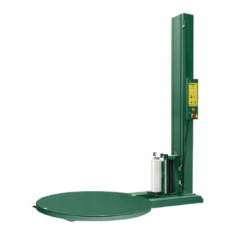
H-1675
110" AutomAtic
stretcH wrAp
dispenser
MACHINE DIMENSIONS
Length
Width
Height
Turntable Diameter
Turntable Height from Floor
Wrapping Height
Operation Space
Maximum Load Size
Approximate Shipping Weight
ELECTRICAL SPECIFICATIONS
115 VAC, 60 Hz, Single-phase, 15 AMP
TURNTABLE SYSTEM
20 loads per hour (spiral)
12 RPM turntable maximum speed
4,000 lbs turntable maximum load capacity
FILM CARRIAGE / ELEVATOR SYSTEM
Adjustable raise and lower speeds
Automatic height detection photoelectric
sensor
FILM DELIVERY SYSTEM
Infinite / Manual Stretch Adjustment
10" Diameter Roll Capacity
20" Roll Width Capacity
PAGE 1 OF 11
1-800-295-5510
uline.com
SYSTem SpecificaTionS
99"
60"
129"
59"
3"
110"
99 x 60 x 129"
52 x 52 x 110"
1,250 lbs
caUTion! motor control equipment and
electronic controllers are connected to
hazardous line voltages. When servicing
drive and controllers, there may be exposed
components with housings or protrusions at or
above line potential. extreme care should be
taken to protect against shock.
The user is responsible for conforming to all
applicable code requirements with respect to
grounding requirements. Do noT use extension
cords to operate the equipment.
Disconnect ac input power before checking
components, performing maintenance,
cleaning up, and when the machine is not in
use. Do noT connect or disconnect wires and
connectors while power is applied to circuit.
Wiring work should be performed only by
qualified personnel. There is a danger of
electric shock or fire.
WaRninG! Loose clothing must noT be worn
while the machine is in operation. Stay clear
of moving parts while the machine is running.
0813 IH-1675
Advertisement
Table of Contents

Related Manuals for U-Line H-1675


Summary of Contents for U-Line H-1675
- Page 1 π H-1675 1-800-295-5510 uline.com 110" AutomAtic stretcH wrAp dispenser SYSTem SpecificaTionS MACHINE DIMENSIONS caUTion! motor control equipment and electronic controllers are connected to Length 99" hazardous line voltages. When servicing drive and controllers, there may be exposed Width 60" components with housings or protrusions at or Height 129"...
-
Page 2: System Description
SYSTem DeScRipTion Control Box Tower Stretch Handle Tension Adjustment Knob Film Carriage Foot Safety Bar Motor Box Seat Turntable PAGE 2 OF 11 0813 IH-1675... -
Page 3: System Setup
SYSTem SeT-Up MACHINE PLACEMENT MACHINE SET-UP Place the Automatic Stretch Wrap Machine close to 1. Place skidded machine close to the designated an area where you will be wrapping your pallet loads. wrap area. Remove all shipping fasteners holding Make sure that there is sufficient room to load/unload the machine to the pallet. - Page 4 The H-1675 will arrive with similar crating to what is shown to the right. Please remove the protective packaging and prepare the unit to stand up. (See Figure 2) Figure 2 2. Once the machine has been successfully uncrated, the next step is to begin erecting the tower.
- Page 5 aSSembLY inSTRUcTionS conTinUeD 5. Loosen the top 2 bolts to hang the carriage in place. (See Figure 6) Figure 6 6. Align the top two bolts with slotted bolt holes at the top of the carriage and hang in place. (See Figure 7) Figure 7 7.
-
Page 6: Control Box
conTRoL boX INFO WRAP TURNTABLE MODES WRAPS SYSTEM BOTTOM CARRAIGE RESET WRAPS START BANDING TURNTABLE CARRIAGE SPEED SPEED PAGE 6 OF 11 0813 IH-1675... -
Page 7: Led Display
conTRoL boX conTinUeD LeD DiSpLaY Emergency Stop Condition System is normal Mode A Selected Mode B Selected Continue operation by pushing START button System is in Manual bUTTonS WRAPPING MODE A - WRAP UP AND DOWN The LED on the button’s upper left is on. In Mode A, the bottom wrap is applied first, and then the top wrap follows. - Page 8 conTRoL boX conTinUeD Push the BOTTOM WRAPS button to select the number of bottom wraps desired (0 - 9). Turn the CARRIAGE SPEED adjustment knob clockwise to increase, and counterclockwise to decrease the carriage speed. This allows you to adjust the overlap of your film. Turn the TURNTABLE SPEED adjustment knob clockwise to increase, and counterclockwise to decrease the turntable speed.
-
Page 9: Machine Operation
macHine opeRaTion FILM LOADING Stretch Handle (Off Position) caUTion! be sure emeRGencY STop is pushed in before threading the film and pulled out Stretch Tension Adjustment Knob when the film is threaded. 1. Place the film on the film mandrel. 2. -
Page 10: Self-Test Procedure
SeLf-TeST pRoceDURe An operator may check the status of the machine DiSpLaY poSSibLe pRobLem LocaTion(S) by running a self-test. If the procedure is carried out Film carriage Safety Bar properly, the INFO screen will display the location of the problem(s). EMERGENCY STOP button Electrical enclosure safety switch To run the self-test, follow the procedure below:... -
Page 11: Troubleshooting
TRoUbLeSHooTinG WaRninG! make sure that only qualified caUTion! Disconnect all power, including personnel perform inspection, troubleshooting external control power that may be present, and part replacement. before servicing the frequency drive controllers. WaiT for three (3) minutes for the Dc bus capacitors to discharge. The frequency drive controller’s display and/or LeDs are not accurate indicators of the absence of Dc bus voltage.
Need help?
Do you have a question about the H-1675 and is the answer not in the manual?
Questions and answers