Table of Contents
Advertisement
Available languages
Available languages
Quick Links
Advertisement
Table of Contents

Subscribe to Our Youtube Channel
Related Manuals for U-Line H-1119


Summary of Contents for U-Line H-1119
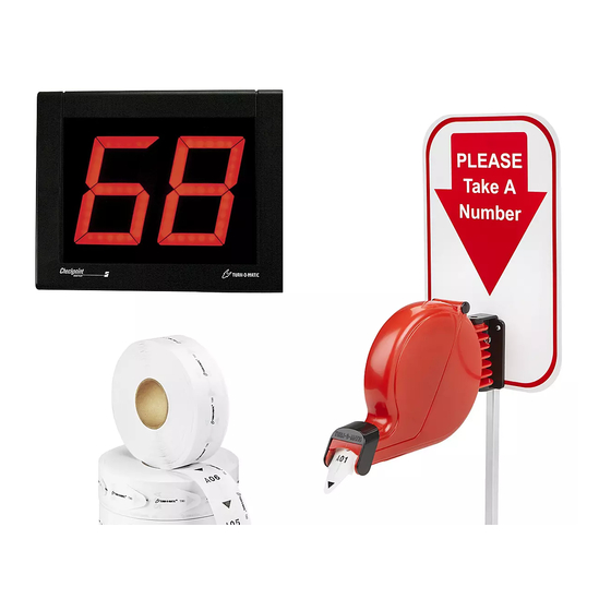
- Page 1 Para Español, vea páginas 7-12. Pour le français, consulter les pages 13-18. H-1119 1-800-295-5510 uline.com TAKE-A-NUMBER SYSTEM TOOLS NEEDED Large Flathead Screwdriver Mini Flathead Screwdriver Phillips Screwdriver Wire Cutter PAGE 1 OF 18 0421 IH-1119...
-
Page 2: Parts List
PARTS LIST COUNT PIECES BEFORE ASSEMBLING CONTENTS OF SMALL BOX INSIDE THE DISPENSER (Dispenser) Large Slotted Screw x 3 Large Slotted Bolt x 2 Dispenser Mounting Bracket x 1 Nut x 2 Dispenser x 1 CONTENTS OF LARGE RECLOSABLE BAG (Stand and Wiring) Allen Wrench x 1 (used to disconnect... -
Page 3: Operation
OPERATION AND USE OF DISPENSER OPERATION NOTE: For permanent mounting, use the base of stand as a template, mark and drill four 1. Customer takes a number from the dispenser and holes and secure base of stand to surface with waits until the number appears on the display. -
Page 4: Electronic Display
DISPLAY – MOUNTING AND INSTALLATION ELECTRONIC DISPLAY 4. Secure push buttons to surface using the two included slotted screws. (Optional) MOUNTING BRACKET TO WALL 5. Repeat steps 1–3 with the two remaining push 1. Determine where to place the display so it is easily buttons. - Page 5 DISPLAY – MOUNTING AND INSTALLATION CONTINUED PLUGGING DATA CONNECTOR INTO DISPLAY 3. Plug the power connector into either of the two power receptacles located on the back of the (CONTINUED) display. (See Figure 15) 3. Mark which push button is plugged into the (+) and 4.
- Page 6 DISPLAY – MOUNTING AND INSTALLATION CONTINUED DISPLAY START-UP Delay Time (seconds) The display shows a number of messages on start-up once it is plugged in. Display shows: Range: 00–29 • Program version: "P-", then number • TOM-Net address: 'ad", then 51 or 21 Sleep Time (seconds) •...
-
Page 7: Herramientas Necesarias
H-1119 800-295-5510 uline.mx SISTEMA TOMATURNOS HERRAMIENTAS NECESARIAS Desarmador Grande de Cabeza Plana Minidesarmador de Cabeza Plana Desarmador de Cruz Cortacables PAGE 7 OF 18 0421 IH-1119... -
Page 8: Lista De Partes
LISTA DE PARTES CUENTE LAS PIEZAS ANTES DE ENSAMBLAR CONTENIDO DE LA CAJA PEQUEÑA DENTRO DEL DESPACHADOR (Despachador) 3 Tornillos Ranurados Grandes 2 Pernos Ranurados Grandes 1 Soporte de Montaje 2 Tuercas del Despachador 1 Despachador 1 Llave Allen (para desconectar la placa inferior del poste CONTENIDO DE LA BOLSA GRANDE de la base) - Page 9 FUNCIONAMIENTO Y USO DEL DESPACHADOR FUNCIONAMIENTO NOTA: Para un montaje permanente utilice la placa como plantilla, marque y taladre cuatro 1. El cliente toma un número del despachador y espera orificios y asegure la placa de la base a la a que el número aparezca en la pantalla.
- Page 10 PANTALLA - MONTAJE E INSTALACIÓN PANTALLA ELECTRÓNICA 4. Fije los botones pulsadores a la superficie usando los dos tornillos ranurados incluidos. (Opcional) MONTAJE DEL SOPORTE EN LA PARED 5. Repita los pasos 1–3 con los dos botones pulsadores 1. Decida el lugar para colocar la pantalla de forma restantes.
- Page 11 CONTINUACIÓN DE PANTALLA - MONTAJE E INSTALACIÓN CONTUNUACIÓN DE ENCHUFAR 3. Enchufe el conector de electricidad en cualquiera de los dos orificios de corriente ubicados en la EL CABLE DE DATOS A LA PANTALLA parte posterior de la pantalla. (Vea Diagrama 15) 3.
- Page 12 CONTINUACIÓN DE PANTALLA - MONTAJE E INSTALACIÓN ENCENDER LA PANTALLA Tiempo de Retraso (segundos) La pantalla muestra una serie de mensajes mientras se enciende una vez enchufada. La pantalla muestra: Rango: 00 a 29 • Versión del Programa: "P-", luego el número •...
-
Page 13: Outils Requis
H-1119 1-800-295-5510 uline.com SYSTÈME « PRENEZ UN NUMÉRO » OUTILS REQUIS Grand tournevis à tête plate Mini tournevis à tête plate Tournevis cruciforme Coupe-fils PAGE 13 OF 18 0421 IH-1119... - Page 14 PIÈCES COMPTEZ LES PIÈCES AVANT D'ASSEMBLER ARRÊT ARRÊT CONTENU DE LA PETITE BOÎTE INTÉRIEUR DU DISTRIBUTEUR : (distributeur) Longues vis fendues x 3 Longs boulons à encoches x 2 Support de fixation du distributeur x 1 Écrous x 2 Distributeur x 1 Clé Allen x 1 (utilisée pour séparer la base inférieure CONTENU DU GRAND SAC REFERMABLE...
-
Page 15: Fixation Murale
FONCTIONNEMENT ET UTILISATION DU DISTRIBUTEUR FONCTIONNEMENT REMARQUE : Pour installer le pied de façon permanente, marquez et percez quatre trous 1. Le client saisit un billet du distributeur et attend que en utilisant la base du pied comme guide, son numéro s'affiche sur l'indicateur. puis fixez et sécurisez la base du pied à... - Page 16 INDICATEUR – MONTAGE ET INSTALLATION INDICATEUR ÉLECTRONIQUE 4. Fixez les boutons-poussoirs à la surface à l'aide des deux vis fendues fournies. (facultatif) FIXER LE SUPPORT AU MUR 5. Répétez les étapes 1 à 3 avec les deux autres 1. Déterminez où installer l'indicateur afin qu'il puisse boutons-poussoirs restants.
- Page 17 INDICATEUR – MONTAGE ET INSTALLATION SUITE BRANCHEMENT DU CONNECTEUR 3. Branchez le câble d'alimentation dans l'une des deux prises d'alimentation situées à l'endos de DE DONNÉES À L'INDICATEUR SUITE l'indicateur. (Voir Figure 15) 3. Marquez le bouton-poussoir branché dans la prise (+) 4.
- Page 18 INDICATEUR – MONTAGE ET INSTALLATION SUITE DÉMARRAGE DE L'INDICATEUR Délai (en secondes) Au démarrage, l'indicateur affiche un certain nombre de messages lorsqu'il est branché. L'indicateur affiche : • Version du programme : « P- », puis le numéro • Adresse TOM-Net : « Ad », puis 51 ou 21 Mise en veille (en secondes) •...
Need help?
Do you have a question about the H-1119 and is the answer not in the manual?
Questions and answers