Table of Contents
Advertisement
Quick Links
QUESTIONS?
Ask the experts at POSMicro.com.
1.800.241.6264
Live Chat Now
support@POSMicro.com
Monday - Friday 6 AM to 5 PM Pacific Time
1.800.241.6264
Datalogic PowerScan
D8300 Manual
More information available at
BULk DISCOUNTS
FREE SHIPPING*
*Free ground shipping to the continental USa on orders over $100.
For Help Call
POSMicro.com
SE HaBLa
ESpañOL
Advertisement
Table of Contents

Related Manuals for Datalogic PowerScan D8300


Summary of Contents for Datalogic PowerScan D8300
- Page 1 For Help Call 1.800.241.6264 Datalogic PowerScan D8300 Manual More information available at POSMicro.com QUESTIONS? BULk DISCOUNTS SE HaBLa Ask the experts at POSMicro.com. ESpañOL FREE SHIPPING* 1.800.241.6264 Live Chat Now support@POSMicro.com Monday - Friday 6 AM to 5 PM Pacific Time...
- Page 2 ® PowerScan D8330/M8300/M8300-DK Reference Manual...
- Page 3 An Unpublished Work - All rights reserved. No part of the contents of this docu- mentation or the procedures described therein may be reproduced or transmit- ted in any form or by any means without prior written permission of Datalogic Scanning, Inc. or its subsidiaries or affiliates ("Datalogic" or “Datalogic Scan- ning”).
-
Page 4: Table Of Contents
Master BC-8060 Network Troubleshooting ..........23 CONFIGURATION ..................24 Configuration Methods ................24 4.1.1 Reading Configuration Barcodes ..............24 4.1.2 Using Datalogic Aladdin™ ................24 4.1.3 Copy Command ..................24 4.1.4 Sending Configuration Strings from Host ............ 25 Setup Procedures ..................25 ®... - Page 5 ® POWERSCAN D8330/M8300/M8300-DK ® PowerScan M8300/STAR-System™ Setup ..........31 BC-8060 STAR-System™ Network Setup ..........33 Interface Selection ..................35 USB Reader Configuration ................38 4.10 Changing Default Settings ................40 RS-232 Parameters ..................41 USB Parameters ..................46 Wedge Parameters ..................52 Pen Emulation .....................
- Page 6 5.5.2 Enter Sleep Timeout ................. 177 Reading Parameters ................. 177 5.6.1 Trigger Signal .................... 177 5.6.2 Trigger Click ....................177 5.6.3 Trigger-Off Timeout ................... 177 5.6.4 Reads per Cycle ..................177 5.6.5 Safety Time ....................178 Decoding Parameters ................178 5.7.1 Ink-Spread ....................
- Page 7 ® POWERSCAN D8330/M8300/M8300-DK 6.3.5 Setting RTC ....................200 Messages from SCANNER Command Keys ..........201 6.4.1 PowerScan M8300 keypad ............... 201 6.4.2 PowerScan M8300-DK 16-key keypad ............. 202 TECHNICAL FEATURES ................. 203 ® PowerScan D8330 .................. 203 ® PowerScan M8300 .................. 204 ®...
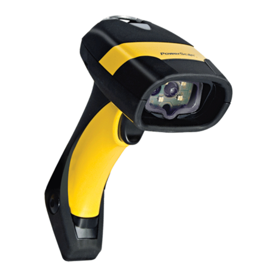
- Page 8 GENERAL VIEW GENERAL VIEW ® POWERSCAN D8330/M8300 READERS LEDs ® POWERSCAN D8330 Cable Connector ® POWERSCAN M8300 Battery Cover Laser Output Window Trigger ® Figure A – PowerScan D8330/M8300 Series Readers Laser Output Window Display Keypad LEDs ® Figure B – PowerScan M8300 Series Readers with Display...
- Page 9 ® POWERSCAN D8330/M8300/M8300-DK BC-80X0 / C-8000 CRADLES Scan Finder Button LEDs Figure C – BC-8000 The label on the cradle contains LED indicators and a scan finder button. When the button is pressed, the cradle transmits a “broadcast” message. All properly configured scanners (Radio RX Timeout set to keep the radio “awake”) linked to that base (through a bind or a join sequence) and within radio range coverage will emit a beep sequence once every 2 seconds for 30 seconds.
-
Page 10: Introduction
INTRODUCTION INTRODUCTION ® Datalogic renews its range of industrial laser scanners introducing the PowerScan ® ® family: PowerScan D8330 and PowerScan M8300. Robustness and ergonomics remain unsurpassed: clearly audible beeper and bright "good read" LEDs for areas where noise levels are normally high; the aim mode, which helps point to the right ®... -
Page 11: Installation
® POWERSCAN D8330/M8300/M8300-DK INSTALLATION Connections should always be made with power OFF! CAUTION ® POWERSCAN D8330 INTERFACE CABLE CONNECTIONS ® The PowerScan D8330 reader incorporates a multi-standard interface, which can be connected to a Host by plugging the correct interface cable into the connector and closing the cable cover. - Page 12 INSTALLATION Follow the given procedure for correct cable insertion: Align Notch Arrow Slip the cover over the cable. Push the plastic boot into the rubber gasket. Take care that the tab on the plastic boot is aligned with the notch in the rubber gasket. ...
-
Page 13: Bc-80X0 Interface Cable Connections
® POWERSCAN D8330/M8300/M8300-DK BC-80X0 INTERFACE CABLE CONNECTIONS Power Interface Cable BC-80X0 Connectors The BC-80X0 incorporates a multi-standard interface, which can be connected to a Host by simply plugging the correct interface cable into the Host connector, placed on the base of the cradle. In addition the cradle must be connected to an external power supply. -
Page 14: Connection
INSTALLATION RS-232 CONNECTION (if required) -
Page 15: Ibm Usb Pos
® POWERSCAN D8330/M8300/M8300-DK IBM USB POS (if required) -
Page 16: Wedge Connection
INSTALLATION WEDGE CONNECTION PEN EMULATION CONNECTION... -
Page 17: Network Connections
RS-232, USB, Wedge, (BC-8060only) PEN Emulation All cradles are connected together within the bus system through the Datalogic RS-485 splitter cable (CAB-428, part number 90A051950), which must be inserted in the RS-485 cradle connector. Obviously cable length is to be kept to a minimum as with all bus systems. -
Page 18: Network Cabling
INSTALLATION 2.8.2 Network Cabling The Multidrop line is made using RJ45 connectors and a cable having the following specifications: • twisted pair AWG 24 wires • 120 Ω impedance • maximum network cable length 1200 meters Function Multidrop Cables RS-485 + Pin 1 Data RS-485 -... -
Page 19: Network Termination
® POWERSCAN D8330/M8300/M8300-DK 2.8.3 Network Termination The first and last cradles of the chain (the two ends of the bus) must be properly terminated. The cradle has an internal terminator that can be selected via jumper. For this selection you must open the device. No Termination Static Dynamic... -
Page 20: Powerscan M8300 Battery Maintenance
INSTALLATION ® POWERSCAN M8300 BATTERY MAINTENANCE 2.9.1 Battery Charging ® Once the system is connected and powered, you can place the PowerScan M8300 into the cradle to charge the battery. When the reader is correctly inserted in the cradle, the "Reader" red LED on the cradle goes on to indicate that the battery is charging. -
Page 21: 2.10 Mounting The Bc-80X0 / C-8000 Cradle
® POWERSCAN D8330/M8300/M8300-DK 2.10 MOUNTING THE BC-80X0 / C-8000 CRADLE The cradle package contains the following items: BC-80X0 / C-8000 Cradle BC-80X0 Quick Reference / C-8000 Quick Reference BC-8000 Antenna 2 wall-mounting lock hinges 2 adhesive strips 4 rubber feet 1 horizontal base 1 inclined base The cradle (either BC-80X0 or C-8000) can be mounted for portable or fixed desktop... -
Page 22: Desktop Mounting
INSTALLATION 2.10.1 Desktop Mounting For desktop usage, you can mount the cradle either on the horizontal base, for reduced overall dimensions, or on the inclined base for a more ergonomic taking out and insertion of the reader onto the cradle. Horizontal base Rubber Foot Mounting... - Page 23 ® POWERSCAN D8330/M8300/M8300-DK Portable Desktop Use Correctly position the BC-80X0/C-8000 onto the base by sliding it along the mounting tabs until aligned. Carefully clean the rubber foot seats of the base to remove any impurities that could reduce adhesion. Remove the protective plastic from the rubber feet and stick them onto the bottom surface of the base.
- Page 24 INSTALLATION Position the cables to be connected to the BC-80X0/C-8000 cradle along the dedicated channels, as shown in the figures below: Horizontal Base Inclined Base Remove the plastic from the other side of the strips and affix the base to the table.
-
Page 25: Wall Mounting
® POWERSCAN D8330/M8300/M8300-DK 2.10.2 Wall Mounting Remove the yellow caps and insert the two wall mounting lock hinges provided with your cradle. Position the cables to be connected to the BC-80X0/C-8000 cradle along the dedicated channels (see figures at page 14). - Page 26 INSTALLATION If using the adhesive strips: If using the mounting screws: Carefully clean the adhesive strip Using the mounting holes on the seats of the base to remove any base as a pattern, mark the wall impurities that could reduce where you desire to mount the BC- adhesion.
-
Page 27: Powerscan M8300 System And Network Layouts
® POWERSCAN D8330/M8300/M8300-DK ® POWERSCAN M8300 SYSTEM AND NETWORK LAYOUTS There are two basic system layouts that can be employed: Stand-alone systems (including Point-to-Point layouts) and Multidrop STAR-System™ Networks. STAND-ALONE LAYOUTS 3.1.1 Point-to-Point Reader Layout 3.1.2 Stand-Alone Layout with Multiple Readers In stand-alone systems, each cradle is connected to a single Host. -
Page 28: Multiple Stand-Alone Layouts
® POWERSCAN M8300 SYSTEM AND NETWORK LAYOUTS 3.1.3 Multiple Stand-Alone Layouts Many stand-alone connections can operate in the same physical area without interference, provided all readers and cradles in the system have different addresses. JOIN ® PowerScan M8300 ® PowerScan JOIN M8300 Host... -
Page 29: C-Box Layout
® POWERSCAN D8330/M8300/M8300-DK 3.1.4 C-BOX Layout ® PowerScan M8300 JOIN Scanner BIND C-Box BC-80X0 System cables to Host In this layout the BC-80X0 cradle is connected by a dedicated cable using the RS-232 interface to a C-BOX connection box as part of a fixed scanner network. This allows the flexibility of a hand-held reading station integrated into a variety of fixed scanning applications so that all readers (both fixed and hand-held), in the system provide communications to the Host. -
Page 30: Multidrop Star-System™ Network Layouts
The Slaves at the ends of the network must be terminated (see the STARGATE™ and STAR-Box™ Installation Manuals and par. 2.8.3 See par. 4.6 and 4.7 or the Datalogic Aladdin™ Help On-Line for system configuration specifications. -
Page 31: Bc-8060 Master Layout
STARGATE™ base stations can also be used as slaves in this network. The devices at the ends of the network must be terminated (see par. 2.8.3 See pars. 4.6 and 4.7 or the Datalogic Aladdin™ Help On-Line for system configuration specifications. -
Page 32: Master Bc-8060 Network Troubleshooting
® POWERSCAN M8300 SYSTEM AND NETWORK LAYOUTS 3.2.3 Master BC-8060 Network Troubleshooting Two diagnostic strings can be sent via RS-232 from the Host to the Master cradle in order to have feedback about the network itself. #+LSlave Returns a list of all the Slaves recognized at boot up. Example: In a network where the Master cradle has address 0188 and one Slave cradle with address 0001, the response is:... -
Page 33: Configuration
Using Datalogic Aladdin™ Datalogic Aladdin™ is a multi-platform utility program providing a quick and user- friendly configuration method via the RS-232/USB-COM interface. It also allows upgrading the software of the connected device (see the Datalogic Aladdin™ Help On-Line for more details). 4.1.3... -
Page 34: Sending Configuration Strings From Host
CONFIGURATION 4.1.4 Sending Configuration Strings from Host An alternative configuration method is provided in Appendix A using the RS-232 interface. This method is particularly useful when many devices need to be configured with the same settings. Batch files containing the desired parameter settings can be prepared to configure devices quickly and easily. -
Page 35: Powerscan ® D8330 Setup
® POWERSCAN D8330/M8300/M8300-DK ® POWERSCAN D8330 SETUP Read the restore default parameters code below. ® Restore PowerScan D8330 Default Ì$+$*oÎ After reading the above code, go to par. 4.8 Interface Selection . ® POWERSCAN M8300/BC-80X0 POINT-TO-POINT SETUP A rapid configuration procedure has been devised for point-to-point applications where a single reader is associated exclusively with its own BC-80x0 base station and where it is not necessary to set the Date and Time parameters. - Page 36 CONFIGURATION ® POWERSCAN M8300/BC-80X0 STAND-ALONE SETUP Read the restore default parameters code below. ® Restore PowerScan M8300 Default Ì$+$*oÎ ® Follow the procedure below to set the radio address and bind PowerScan M8300 to the BC-80X0 cradle. Enter Configuration Ì$+;Î Set Date ÌIA%Î...
- Page 37 ® POWERSCAN D8330/M8300/M8300-DK Set Radio Address ÌRA0RFHÎ ® four digits for the PowerScan M8300 Address (from 0000 to 1999). All readers used in the same area must have different addresses. Exit and Save Configuration Ì$-?Î ® Read the Bind code to pair the PowerScan M8300 to the BC-80X0 cradle.
-
Page 38: Using Multiple M-Series Readers With Same Cradle
CONFIGURATION Read the BC-80X0 restore default code: Restore BC-80X0 Default Ì$+RX0$-qÎ Go to par. 4.8 Interface Selection . 4.5.1 Using Multiple M-Series Readers with Same Cradle If you want to use several M-Series readers with the same BC-80X0 cradle, you must first Bind the cradle with one of the readers (see previously described configuration procedure). -
Page 39: Powerscan ® M8300/Star-Modem™ In Stand-Alone Mode
® POWERSCAN D8330/M8300/M8300-DK ® 4.5.2 PowerScan M8300/STAR-Modem™ in Stand-Alone Mode ® To configure a PowerScan M8300 reader to communicate with STAR-Modem™ in Stand-alone Mode, follow the procedure in par. 4.5 substituting steps 6 and 7 with those below: STAR-Modem™ Address ÌRSRÎ... -
Page 40: Powerscan M8300/Star-System™ Setup
CONFIGURATION ® POWERSCAN M8300/STAR-SYSTEM™ SETUP ® The following procedure allows configuring a PowerScan M8300 reader to communicate with various STAR-System™ devices such as STARGATE™ RF base stations. ® Restore PowerScan M8300 Default Ì$+$*oÎ Enter Configuration Ì$+;Î Set Date ÌIA%Î six digits for Day, Month and Year (DDMMYY) Set Time ÌIB'Î... - Page 41 ® POWERSCAN D8330/M8300/M8300-DK Set Radio Address ÌRF8Î four digits from the Numeric Table in the range 0000-1999. All readers must have different addresses. First STAR-System™ Address ÌRSRÎ Read the code above and the four-digit address of the First STAR-System™ device in the system. Set Last STAR-System™...
-
Page 42: Bc-8060 Star-System™ Network Setup
CONFIGURATION BC-8060 STAR-SYSTEM™ NETWORK SETUP When the BC-8060 cradle model is used in an RS-485 network, it must be initially configured. To do this using configuration barcodes, follow the procedure below ® using any PowerScan M8300 reader. Set BC-8060 Address Ì$+RF4Î... - Page 43 For BC-8060 Master Network Layouts (see par. 3.2), The network configuration parameters can be changed either through the Datalogic Aladdin™ configuration software running on the PC or by reading the barcode selections in the Network section of this manual starting on page 64. If using configuration barcodes, it is ®...
-
Page 44: Interface Selection
CONFIGURATION INTERFACE SELECTION Read the interface selection code for your application. RS-232 Standard Ì$+CP0$-$Î POS TERMINALS Nixdorf Mode A Ì$+CM2EC0$->Î Fujitsu Ì$+CM1$-ÈÎ ICL Mode Ì$+CM0$-ÃÎ For POS terminal default settings refer to par. 5.15. Ì$+CP6$-BÎ... - Page 45 ® POWERSCAN D8330/M8300/M8300-DK WEDGE IBM AT or PS/2 PCs Ì$+CP500$-aÎ IBM XT Ì$+CP503$-vÎ PC Notebook Ì$+CP505$-ÈÎ IBM SURE1 Ì$+CP506$-$Î IBM Terminal 3153 Ì$+CP504$-}Î IBM Terminals 31xx, 32xx, 34xx, 37xx: To select the interface for these IBM Terminals, read the correct KEY TRANSMISSION code. Select the KEYBOARD TYPE if necessary (default = advanced keyboard).
- Page 46 CONFIGURATION WEDGE (CONTINUED) ALT MODE The ALT-mode selection allows barcodes sent to the PC to be interpreted correctly independently from the Keyboard Nationality used. You do not need to make a Keyboard Nationality selection. (default = Num Lock Unchanged). Make sure the Num Lock key on your keyboard is ON.
-
Page 47: Usb Reader Configuration
Load drivers from the O.S. (if requested). When configuring the USB-COM interface, the relevant files and drivers must be installed from the USB Device Installation software, which can be downloaded from the web page http://www.scanning.datalogic.com . The device is ready. Successive start-ups will automatically recognize the previously loaded drivers. - Page 48 USB-KBD Ì$+UA03$-:Î USB-KBD-ALT-MODE Ì$+UA04$-@Î USB-KBD-APPLE Ì$+UA05$-FÎ USB-COM* Ì$+UA02$-4Î USB-IBM-Table Top Ì$+UA00$-(Î USB-IBM-Hand Held Ì$+UA01$-.Î When configuring USB-COM, the relevant files and drivers must be installed from the USB Device Installation software, which can be downloaded from the web site http://www.scanning.datalogic.com.
-
Page 49: Changing Default Settings
® POWERSCAN D8330/M8300 4.10 CHANGING DEFAULT SETTINGS Once your reader is setup, you can change the default parameters to meet your application needs. Refer to the preceding paragraphs for initial configuration in order to set the default values and select the interface for your application. In this manual, the configuration parameters are divided into logical groups making it easy to find the desired function based on its reference group. -
Page 50: Rs-232 Parameters
RS-232 PARAMETERS ® All PowerScan D8330 Series readers ® PowerScan M8300/BC-80X0 configurations only ARITY ANDSHAKING ROTOCOL NTER CHARACTER ELAY IMEOUT ERIAL RIGGER Read the Enter Configuration code ONCE , available at the top of each page. - Page 51 Enter Configuration Exit and Save Configuration Ì$+;Î Ì$-?Î RS-232 BAUD RATE 300 baud ÌCD1XÎ 600 baud ÌCD2[Î 1200 baud ÌCD3^Î 2400 baud ÌCD4aÎ 4800 baud ÌCD5dÎ 9600 baud ÌCD6gÎ 19200 baud ÌCD7jÎ 38400 baud ÌCD8mÎ PARITY none ÌCC0SÎ even parity ÌCC1VÎ...
- Page 52 Enter Configuration Exit and Save Configuration Ì$+;Î Ì$-?Î RS-232 DATA BITS 7 bits ÌCA0OÎ 8 bits ÌCA1RÎ 9 bits ÌCA2UÎ STOP BITS 1 stop bit ÌCB0QÎ 2 stop bits ÌCB1TÎ HANDSHAKING disable ÌCE0WÎ hardware (RTS/CTS) ÌCE1ZÎ software (XON/XOFF) ÌCE2]Î...
- Page 53 Enter Configuration Exit and Save Configuration Ì$+;Î Ì$-?Î RS-232 ACK/NACK PROTOCOL disable ÌER0sÎ enable ÌER1vÎ ® See par. 5.1.2 for details, particularly on implementing this parameter with PowerScan M8300. FIFO disable ÌEC0UÎ enable ÌEC1XÎ See par. 5.1.3 for details. INTER-CHARACTER DELAY ...
- Page 54 Enter Configuration Exit and Save Configuration Ì$+;Î Ì$-?Î RS-232 RX TIMEOUT timeout control in reception from Host ÌCL5Î Read 2 numbers from the table where: 00 = TIMEOUT disabled 01-99 = TIMEOUT from .1 to 9.9 seconds rx timeout 5 seconds See par.
-
Page 55: Usb Parameters
USB PARAMETERS USB-COM Handshaking, Ack/Nack protocol, FIFO, Inter-character delay, Rx timeout, Serial trigger lock USB-KBD Keyboard nationality, FIFO, Inter-character delay, Inter-code delay, USB keyboard speed USB-IBM No parameter selection required. Read the Enter Configuration code ONCE , available at the top of each page. Read configuration codes from the desired groups. - Page 56 Enter Configuration Exit and Save Configuration Ì$+;Î Ì$-?Î USB-COM HANDSHAKING disable ÌCE0WÎ hardware (RTS/CTS) ÌCE1ZÎ software (XON/XOFF) ÌCE2]Î RTS always ON ÌCE3`Î See par. 5.1.1 for details. ACK/NACK PROTOCOL disable ÌER0sÎ enable ÌER1vÎ ® See par. 5.1.2 for details, particularly on implementing this parameter with PowerScan M8300.
- Page 57 Enter Configuration Exit and Save Configuration Ì$+;Î Ì$-?Î USB-COM INTER-CHARACTER DELAY delay between characters transmitted to Host ÌCK3Î Read 2 numbers from the table where: 00 = DELAY disabled 01-99 = DELAY from 1 to 99 milliseconds delay disabled RX TIMEOUT ...
- Page 58 Enter Configuratio Exit and Save Configuration Ì$+;Î Ì$-?Î USB-KBD KEYBOARD NATIONALITY Not Available for USB-KBD-ALT-MODE Interface This parameter default value is restored through the Interface Selection code and not Restore Default. Belgian ÌFJ7yÎ English (UK) ÌFJ4pÎ French ÌFJ2jÎ German ÌFJ3mÎ Italian ÌFJ1gÎ...
- Page 59 Enter Configuration Exit and Save Configuration Ì$+;Î Ì$-?Î USB-KBD The Japanese and Eastern Block Keyboard Nationality selections are valid only for IBM AT compatible PCs. Japanese ÌFJ8|Î Russian (Latin) ÌFJ9ÃÎ Russian (Cyrillic) ÌFJA0Î Hungarian ÌFJB3Î Slovenian, Croatian, Serbian (Latin) ÌFJC6Î Romanian ÌFJD9Î...
- Page 60 Enter Configuratio Exit and Save Configuration Ì$+;Î Ì$-?Î USB-KBD INTER-CHARACTER DELAY delay between characters transmitted to Host ÌCK3Î Read 2 numbers from the table where: 00 = DELAY disabled 01-99 = DELAY from 1 to 99 milliseconds delay disabled INTER-CODE DELAY ...
-
Page 61: Wedge Parameters
WEDGE PARAMETERS ® All PowerScan D8330 Series readers ® PowerScan M8300/BC-80X0 configurations only EYBOARD ATIONALITY RECOGNITION NTER CHARACTER ELAY NTER CODE ELAY EYBOARD ETTING EDGE ONTROL HARACTER ... - Page 62 Enter Configuration Exit and Save Configuration Ì$+;Î Ì$-?Î WEDGE KEYBOARD NATIONALITY Belgian ÌFJ7yÎ English (UK) ÌFJ4pÎ French ÌFJ2jÎ German ÌFJ3mÎ Italian ÌFJ1gÎ Spanish ÌFJ6vÎ Swedish ÌFJ5sÎ USA ÌFJ0dÎ...
- Page 63 Enter Configuration Exit and Save Configuration Ì$+;Î Ì$-?Î WEDGE The Japanese and Eastern Block Keyboard Nationality selections are valid only for IBM AT compatible PCs. Japanese ÌFJ8|Î Russian (Latin) ÌFJ9ÃÎ Russian (Cyrillic) ÌFJA0Î Hungarian ÌFJB3Î Slovenian, Croatian, Serbian (Latin) ÌFJC6Î Romanian ÌFJD9Î...
- Page 64 Enter Configuration Exit and Save Configuration Ì$+;Î Ì$-?Î WEDGE CAPS LOCK AUTO-RECOGNITION (IBM AT COMPATIBLE ONLY) disable ÌFP0pÎ enable ÌFP1sÎ NUM LOCK toggle num lock ÌFL1kÎ num lock unchanged ÌFL0hÎ This selection is used together with the Alt Mode interface selection for AT or Notebook PCs. It changes the way the Alt Mode procedure is executed;...
- Page 65 Enter Configuration Exit and Save Configuration Ì$+;Î Ì$-?Î WEDGE INTER-CODE DELAY delay between codes transmitted to Host ÌFG.Î Read 2 numbers from the table where: 00 = DELAY disabled 01-99 = DELAY from 1 to 99 seconds delay disabled KEYBOARD SETTING ALPHANUMERIC KEYBOARD SETTING The device (reader or cradle) can be used with terminals or PCs with various keyboard types...
- Page 66 WEDGE Some ASCII characters may be missing as this depends on the type of keyboard: these are generally particular characters relative to the various national symbologies. In this case: • The first 4 characters (Shift, Alt, Ctrl, and Backspace) can only be substituted with keys not used, or substituted with each other.
- Page 67 Enter Configuration Exit and Save Configuration Ì$+;Î Ì$-?Î WEDGE CONTROL CHARACTER EMULATION Ctrl + Shift + Key ÌFO0nÎ Ctrl + Key ÌFO1qÎ...
-
Page 68: Pen Emulation
PEN EMULATION ® All PowerScan D8330 Series readers ® PowerScan M8300/BC-80X0 configurations only PERATING INIMUM UTPUT ULSE ONVERSION TO VERFLOW UTPUT EVEL EVEL NTER LOCK ELAY Read the Enter Configuration code ONCE , available at the top of each page. - Page 69 PEN EMULATION The operating mode parameters are complete commands and do not require reading the Enter and Exit configuration codes. OPERATING MODE interpret mode Ì$]8Î Interprets commands without sending them to the decoder. transparent mode Ì$[4Î Sends commands to the decoder without interpreting them.
- Page 70 Enter Configuration Exit and Save Configuration Ì$+;Î Ì$-?Î PEN EMULATION MINIMUM OUTPUT PULSE high resolution code emulation 200 µs ÌDG0\Î 400 µs ÌDG1_Î 600 µs ÌDG2bÎ 800 µs ÌDG3eÎ 1 ms ÌDG4hÎ 1.2 ms ÌDG5kÎ low resolution code emulation See par.
- Page 71 Enter Configuration Exit and Save Configuration Ì$+;Î Ì$-?Î PEN EMULATION CONVERSION TO CODE 39 (D8330 SERIES ONLY) disable conversion to Code 39 ÌDA0PÎ Transmits codes in their original enable conversion to Code 39 format. ÌDA1SÎ Converts codes read into Code 39 format.
- Page 72 Enter Configuration Exit and Save Configuration Ì$+;Î Ì$-?Î PEN EMULATION OUTPUT LEVEL normal ÌDD0VÎ (white = logic level 0) inverted ÌDD1YÎ (white = logic level 1) See par. 5.2.4 for details. IDLE LEVEL normal ÌDE0XÎ (black level) inverted ÌDE1[Î...
-
Page 73: Network Parameters
NETWORK PARAMETERS BC-8060 model configurations only RS-485 N ETWORK ETWORK LAVE DDRESS ANGE ETWORK ARNING ESSAGE ECEPTION ARNING ESSAGE ASTER RADLE EADER ASTER RADLE ERMINATOR Read the Enter Configuration code ONCE , available at the top of each page. Read configuration codes from the desired groups. - Page 74 Enter Configuration Exit and Save Configuration Ì$+;Î Ì$-?Î NETWORK PARAMETERS RS-485 NETWORK disable RS-485 network ÌRZ0)Î enable RS-485 slave ÌRZ1,Î enable RS-485 master ÌRZ2/Î See par. 3.2 for details. If a BC-8060 cradle is errantly configured as a Slave but not connected to a network, it may not be able to receive further commands from the reader.
- Page 75 Enter Configuration Exit and Save Configuration Ì$+;Î Ì$-?Î NETWORK PARAMETERS SLAVE ADDRESS RANGE First Address ÌJB(Î Read the code above and the four-digit address of the First Slave device in the system. Last Address ÌJC*Î system. Read the code above and the four-digit address of the Last Slave device in the See par.
- Page 76 Enter Configuration Exit and Save Configuration Ì$+;Î Ì$-?Î NETWORK PARAMETERS MASTER CRADLE HEADER no header ÌJA00/Î one character header ÌJA013Î two character header ÌJA027Î three character header ÌJA03;Î four character header ÌJA04?Î five character header ÌJA05CÎ...
- Page 77 Enter Configuration Exit and Save Configuration Ì$+;Î Ì$-?Î NETWORK PARAMETERS MASTER CRADLE TERMINATOR no terminator ÌJA102Î one character terminator ÌJA116Î two character terminator ÌJA12:Î three character terminator ÌJA13>Î four character terminator ÌJA14BÎ five character terminator ÌJA15FÎ...
-
Page 78: Data Format
DATA FORMAT NOT FOR PEN INTERFACES DENTIFIER USTOM DENTIFIER EADER ERMINATOR PECIAL IELD DJUSTMENT IELD HARACTER ENGTH HARACTER EPLACEMENT DDRESS TAMPING ... - Page 79 (check digit tested or not, check digit tx or not, etc.). • When customizing the Datalogic Standard code identifiers, 1 or 2 identifier characters can be defined for each code type. If only 1 identifier character is required, the second character must be selected as FF (disabled).
- Page 80 define custom code identifier(s) ÌEH/Î Read the above code. (Code Identifiers default to Datalogic standard, see table on previous page). Select the code type from the code table in Appendix for the identifier you want to change.
- Page 81 Enter Configuration Exit and Save Configuration Ì$+;Î Ì$-?Î DATA FORMAT HEADER no header ÌEA00*Î one character header ÌEA01.Î two character header ÌEA022Î three character header ÌEA036Î four character header ÌEA04:Î five character header ÌEA05>Î six character header ÌEA06BÎ...
- Page 82 Enter Configuration Exit and Save Configuration Ì$+;Î Ì$-?Î DATA FORMAT TERMINATOR no terminator ÌEA10-Î one character terminator ÌEA111Î two character terminator ÌEA125Î three character terminator ÌEA139Î four character terminator ÌEA14=Î five character terminator ÌEA15AÎ six character terminator ÌEA16EÎ...
- Page 83 Enter Configuration Exit and Save Configuration Ì$+;Î Ì$-?Î DATA FORMAT SPECIAL KEYS Available only for Wedge IBM AT-PS/2 and USB-KBD Interfaces It is necessary to define each Special Key by following the procedure given in par. 5.4.2. NOTE Select one or more of the following Special Keys according to your needs. Special Key 1 Ì9CÄÎ...
- Page 84 Enter Configuration Exit and Save Configuration Ì$+;Î Ì$-?Î DATA FORMAT FIELD ADJUSTMENT disable field adjustment ÌEF0[Î Field adjustment allows a number of characters n, to be added to or subtracted from the barcode read. The adjustment can be different for each enabled code type. To define the field adjustment: ...
- Page 85 Enter Configuration Exit and Save Configuration Ì$+;Î Ì$-?Î DATA FORMAT FIELD ADJUSTMENT CHARACTER Read the field adjustment character code: field adjustment character ÌEG-Î Read the hexadecimal value corresponding to the character you want to use for field adjustment.
- Page 86 Enter Configuration Exit and Save Configuration Ì$+;Î Ì$-?Î DATA FORMAT CHARACTER REPLACEMENT disable character replacement ÌEO0mÎ This parameter allows up to three characters to be replaced from the barcode read. These substitutions are stored in memory. To define each character replacement: ...
- Page 87 Enter Configuration Exit and Save Configuration Ì$+;Î Ì$-?Î DATA FORMAT Example : The following strings define: First Character Replacement: substitution in Code 39 barcodes of all occurrences of the 0 character with the 1 character. Second Character Replacement: substitution in Code 39 barcodes of all occurrences of the A character with the B character.
- Page 88 Enter Configuration Exit and Save Configuration Ì$+;Î Ì$-?Î DATA FORMAT ADDRESS STAMPING (M8300 SERIES ONLY) disable reader address stamping ÌRU0ÊÎ disable cradle address stamping ÌRW0#Î enable reader address stamping ÌRU1"Î enable cradle address stamping ÌRW1&Î See par. 5.4.3 for details. ADDRESS DELIMITER (M8300 SERIES ONLY) ...
- Page 89 Enter Configuration Exit and Save Configuration Ì$+;Î Ì$-?Î DATA FORMAT TIME STAMPING (M8300 SERIES ONLY) disable ÌIL0kÎ hour/minutes/seconds month/day/year ÌIL1nÎ hour/minutes/seconds day/month/year hour/minutes/seconds ÌIL3tÎ month/day/year ÌIL4wÎ day/month/year ÌIL5zÎ See par. 5.4.5 for details. TIME STAMPING DELIMITER (M8300 SERIES ONLY) enable ...
-
Page 90: Power Save
POWER SAVE LEEP TATE NTER LEEP IMEOUT Read the Enter Configuration code ONCE , available at the top of each page. Read configuration codes from the desired groups. = Read the code and follow the procedure given ... - Page 91 Enter Configuration Exit and Save Configuration Ì$+;Î Ì$-?Î POWER SAVE SLEEP STATE disable ÌBQ0nÎ enable ÌBQ1qÎ See par. 5.5.1 for details. For M8300 series readers, sleep state is entered immediately after reading a code and is not configurable. ENTER SLEEP TIMEOUT ...
-
Page 92: Reading Parameters
READING PARAMETERS RIGGER RIGGER IGNAL RIGGER LICK RIGGER IMEOUT LASH EADS PER YCLE AFETY EEPER NTENSITY EEPER EEPER EEPER ENGTH ... - Page 93 Enter Configuration Exit and Save Configuration Ì$+;Î Ì$-?Î READING PARAMETERS TRIGGER TYPE hardware trigger ÌBK1eÎ Restores TRIGGER MODE software trigger ÌBK0bÎ Enables FLASH MODE always on ÌBK3kÎ TRIGGER SIGNAL trigger active level ÌBA0NÎ trigger active pulse ÌBA1QÎ See par. 5.6.1 for details. TRIGGER CLICK ...
- Page 94 Enter Configuration Exit and Save Configuration Ì$+;Î Ì$-?Î READING PARAMETERS TRIGGER-OFF TIMEOUT trigger-off timeout ÌBD$Î Read 2 numbers in the range 00-99: 00 = disables the trigger-off timeout 01-99 = corresponds to a max. 99-sec. delay after the trigger press to allow the reader to turn off automatically.
- Page 95 Enter Configuration Exit and Save Configuration Ì$+;Î Ì$-?Î READING PARAMETERS SAFETY TIME safety time ÌBE&Î Limits same code consecutive reading. Read 2 numbers in the range 00-99: 00 = no same code consecutive reading until reader is removed (no decoding) for at least 400 ms. 01-99 = timeout from .1 to 9.9 seconds before a consecutive read on same code.
- Page 96 Enter Configuration Exit and Save Configuration Ì$+;Î Ì$-?Î READING PARAMETERS BEEPER TONE tone 1 ÌBH0\Î tone 2 ÌBH1_Î tone 3 ÌBH2bÎ tone 4 ÌBH3eÎ BEEPER TYPE monotone ÌBJ0`Î bitonal ÌBJ1cÎ BEEPER LENGTH long ÌBI0^Î short ÌBI1aÎ...
- Page 97 Enter Configuration Exit and Save Configuration Ì$+;Î Ì$-?Î READING PARAMETERS GOOD READ SPOT DURATION disable ÌBV0xÎ short ÌBV1{Î medium ÌBV2~Î long ÌBV3ÅÎ AIMING SYSTEM disabled ÌBj09Î enabled ÌBj1<Î CRADLE BEEPER INTENSITY disable ÌJI0fÎ low intensity ÌJI1iÎ medium intensity ÌJI2lÎ...
-
Page 98: Decoding Parameters
DECODING PARAMETERS PREAD VERFLOW ONTROL NTERDIGIT ONTROL ECODING AFETY ™ UZZLE OLVER Before changing these parameter values read the descriptions in par. 5.7. CAUTION Read the Enter Configuration code ONCE , available at the top of each page. Read configuration codes from the desired groups. - Page 99 Enter Configuration Exit and Save Configuration Ì$+;Î Ì$-?Î DECODING PARAMETERS INK SPREAD disable ÌAX0{Î enable ÌAX1~Î See par. 5.7.1 for details. OVERFLOW CONTROL disable ÌAW1|Î enable ÌAW0yÎ See par. 5.7.2 for details. INTERDIGIT CONTROL disable ÌAV0wÎ enable ÌAV1zÎ...
- Page 100 Enter Configuration Exit and Save Configuration Ì$+;Î Ì$-?Î DECODING PARAMETERS DECODING SAFETY one read ÌED0WÎ (decoding safety disabled) two reads ÌED1ZÎ three reads ÌED2]Î four reads ÌED3`Î Required number of good reads before accepting code. PUZZLE SOLVER™ disable ÌAU0uÎ...
-
Page 101: Code Selection
CODE SELECTION CONFIGURATION EAN/UPC F AMILY 2/5 F AMILY 39 F AMILY 128 F AMILY ODABAR AMILY ... - Page 102 Code selections may be performed according to two different procedures: Auto-configuration, allowing an automatic recognition and selection of the code families to be read; Manual configuration, requiring configuration and selection of each code family to be read. AUTO-CONFIGURATION The following codes do not require reading the Enter and Exit configuration codes. In auto-configuration mode the reader enters a particular state, during which it reads, recognizes and saves all information received from the decoding of an existing code (with the exception of MSI, Code 49 and Code 16k code types).
- Page 103 Enter Configuration Exit and Save Configuration Ì$+;Î Ì$-?Î CODE SELECTION DISABLE ALL CODE FAMILIES ÌAZ0ÃÎ The reader allows up to 10 code selections. This does not limit the number of CODES enabled to 10, as it depends on the code family. NOTE SINGLE •...
- Page 104 Enter Configuration Exit and Save Configuration Ì$+;Î Ì$-?Î CODE SELECTION EAN/UPC FAMILY disable the family ÌAA0MÎ Read the desired family code NOTE: Since the EAN/UPC without ADD ON code selection is enabled by default, to correctly enable another selection, first disable the family. EAN 8/EAN 13/UPC A/UPC E with and without ADD ON ÌAA8eÎ...
- Page 105 Enter Configuration Exit and Save Configuration Ì$+;Î Ì$-?Î CODE SELECTION WITH ADD ON 2 ONLY EAN 8/EAN 13 ÌAAK7Î UPC A/UPC E ÌAAM=Î WITH ADD ON 5 ONLY EAN 8/EAN 13 ÌAAL:Î UPC A/UPC E ÌAAN@Î WITH AND WITHOUT ADD ON ...
- Page 106 Enter Configuration Exit and Save Configuration Ì$+;Î Ì$-?Î CODE SELECTION SELECT EAN/UPC PREFIXES When scanning the following codes, barcodes starting with the selected prefixes will be read and transmitted only if the ADD ON is present . If no ADD ON is found, the barcode will not be read.
- Page 107 Enter Configuration Exit and Save Configuration Ì$+;Î Ì$-?Î CODE SELECTION Example : The following string allows reading and transmitting with ADD ON all EAN/UPC starting with the 434/439, 977 and 978 prefixes: EAN/UPC Autodiscrimination ADD ON by Prefix. 434/439: enables reading and transmission with ADD ON of all EAN/UPC barcodes starting with 434/439 prefixes.
- Page 108 Enter Configuration Exit and Save Configuration Ì$+;Î Ì$-?Î CODE SELECTION EAN/UPC CHECK DIGIT TX SELECTIONS For each code type in this family you can choose to transmit the check digit or not CHECK DIGIT TRANSMISSION NO CHECK DIGIT TRANSMISSION EAN 8 ÌAAG1oÎ...
- Page 109 Enter Configuration Exit and Save Configuration Ì$+;Î Ì$-?Î CODE SELECTION CONVERSION OPTIONS UPC E to UPC A conversion ÌAAAÄÎ UPC E to EAN 13 conversion ÌAABÇÎ UPC A to EAN 13 conversion ÌAACÊÎ EAN 8 to EAN 13 conversion ÌAAD"Î Enable only ISBN conversion ÌAP1nÎ...
- Page 110 Enter Configuration Exit and Save Configuration Ì$+;Î Ì$-?Î CODE SELECTION 2/5 FAMILY disable the family ÌAC0QÎ Read the desired family code Read a check digit selection Interleaved 2/5 ÌAC1TÎ CHECK DIGIT TABLE no check digit control Ì12Î...
- Page 111 Enter Configuration Exit and Save Configuration Ì$+;Î Ì$-?Î CODE SELECTION CODE 39 FAMILY disables the family ÌAB0OÎ Read the desired family code Read a check digit selection CHECK DIGIT TABLE Standard Code 39 no check digit control ÌAB1RÎ...
- Page 112 Enter Configuration Exit and Save Configuration Ì$+;Î Ì$-?Î CODE SELECTION CODE 128 FAMILY disable the family ÌAI0]Î Read the desired family code Code 128 ÌAI11=Î control without transmission of ISBT 128 check digit ÌAI31CÎ enabling ISBT 128 automatically EAN 128 disables Puzzle Solver™.
- Page 113 Enter Configuration Exit and Save Configuration Ì$+;Î Ì$-?Î CODE SELECTION CODE 93 disable the code ÌAK0aÎ Code 93 ÌAK1dÎ control without transmission of check digit CODABAR FAMILY disable the family ÌAD0SÎ Read the desired equality control code Read a start/stop transmission selection START/STOP CHARACTER...
- Page 114 Enter Configuration Exit and Save Configuration Ì$+;Î Ì$-?Î CODE SELECTION The Codabar ABC code below uses a fixed start/stop character transmission selection. Codabar ABC ÌAD212)Î no start/stop character equality control but transmission. Codabar ABC Forced Concatenation enable Codabar ABC with forced concatenation ÌAD2321Î...
- Page 115 Enter Configuration Exit and Save Configuration Ì$+;Î Ì$-?Î CODE SELECTION disable the family ÌAE0UÎ Enable the code by selecting one of the check digit selections. no check digit control ÌAE1XÎ MOD10 check digit control no check digit transmission ÌAE2[Î MOD10 check digit control check digit transmission ÌAE3^Î...
- Page 116 Enter Configuration Exit and Save Configuration Ì$+;Î Ì$-?Î CODE SELECTION CODE 11 disable the family ÌAG0YÎ Enable the code by selecting one of the check digit selections. no check digit control ÌAG1\Î Type C check digit control check digit transmitted ÌAG21<Î...
- Page 117 Enter Configuration Exit and Save Configuration Ì$+;Î Ì$-?Î CODE SELECTION CODE 16K disable the code ÌAJ0_Î Code 16K ÌAJ1bÎ To read stacked codes, simply move the reader over the code so that each line of the code is scanned. During this process a series of brief “ticks” indicates that reading is proceeding correctly.
- Page 118 Enter Configuration Exit and Save Configuration Ì$+;Î Ì$-?Î CODE SELECTION GS1 DATABAR™ CODES disable the family ÌAQ0mÎ DISABLE CODE ENABLE CODE disable GS1 DataBar Expanded Linear and Stacked ÌAQ10IÎ enable GS1 DataBar Expanded Linear and Stacked ÌAQ11MÎ disable GS1 DataBar Limited ÌAQ20LÎ...
-
Page 119: Advanced Formatting
ADVANCED FORMATTING NOT FOR PEN INTERFACES ONCATENATION DVANCED ORMATTING Please follow the setup procedure carefully for these parameters. NOTE The Advanced Formatting parameters may not be compatible with the IBM USB POS interface selection. NOTE Read the Enter Configuration code ONCE , available at the top of page. Read configuration codes precisely following the numbered procedure given. - Page 120 Enter Configuration Exit and Save Configuration Ì$+;Î Ì$-?Î ADVANCED FORMATTING CONCATENATION disable ÌEI0aÎ enable ÌEI1dÎ Permits the concatenation of two codes defined by code type and length. It is possible to set a timeout for the second code reading and to define code transmission if the timeout expires. The order of transmission is CODE 1-CODE 2.
- Page 121 Since you can concatenate codes from different families, you must select the Code ID character of the resulting code. The Code ID character will be sent in the output message only if it is enabled according to the Code Identifier selection (Datalogic, AIM, or Custom). Concatenation Timeout timeout ÌEJ3Î...
- Page 122 Exit and Save Configuration Ì$-?Î ADVANCED FORMATTING Transmission after Timeout no code transmitted after timeout ÌEM0iÎ only code 1 transmitted (if read) after timeout ÌEM1lÎ only code 2 transmitted (if read) after timeout ÌEM2oÎ either code 1 or code 2 transmitted after timeout ÌEM3rÎ...
- Page 123 ADVANCED FORMATTING ADVANCED FORMATTING Advanced formatting has been designed to offer you complete flexibility in changing the format of barcode data before transmitting it to the host system. This formatting will be performed when the barcode data meets certain criteria, which you will define in the following procedure. Up to 4 advanced code management formats can be defined and saved in memory.
- Page 124 Enter Configuration Exit and Save Configuration Ì$+;Î Ì$-?Î ADVANCED FORMATTING Begin Format Definition begin Format 1 definition ÌHA0TÎ begin Format 2 definition ÌHA1WÎ begin Format 3 definition ÌHA2ZÎ begin Format 4 definition ÌHA3]Î Match Code Type match code type ÌHB&Î...
- Page 125 Exit and Save Configuration Ì$-?Î ADVANCED FORMATTING Match with Predefined Characters no match ÌHD0HE00ÄÎ match with 1 character ÌHD1]Î match with a 2-character string ÌHD2`Î match with a 3-character string ÌHD3cÎ match with a 4-character string ÌHD4fÎ ...
- Page 126 Exit and Save Configuration Ì$-?Î ADVANCED FORMATTING Divide Code into Fields divide code into fields ÌHF.Î Read one number in the range 1 to 5 to divide the code into fields. Define Code Fields define code fields Each code field length can be set by either: a) defining a field separator character to be found in the code itself .
- Page 127 Exit and Save Configuration Ì$-?Î ADVANCED FORMATTING DEFINE FIELD 1 BY: EITHER field separator ÌHG0`Î Read the field separator character from the HEX table. Range of characters = 00-FE. discard separator include separator Ì01Î Ì12Î match character ÌHG3iÎ Read the match character from the HEX table.
- Page 128 Exit and Save Configuration Ì$-?Î ADVANCED FORMATTING DEFINE FIELD 2 BY: EITHER field separator ÌHG0`Î Read the field separator character from the HEX table. Range of characters = 00-FE. discard separator include separator Ì01Î Ì12Î match character ÌHG3iÎ Read the match character from the HEX table.
- Page 129 Exit and Save Configuration Ì$-?Î ADVANCED FORMATTING DEFINE FIELD 3 BY: EITHER field separator ÌHG0`Î Read the field separator character from the HEX table. Range of characters = 00-FE. discard separator include separator Ì01Î Ì12Î match character ÌHG3iÎ Read the match character from the HEX table.
- Page 130 Exit and Save Configuration Ì$-?Î ADVANCED FORMATTING DEFINE FIELD 4 BY: EITHER field separator ÌHG0`Î Read the field separator character from the HEX table. Range of characters = 00-FE. discard separator include separator Ì01Î Ì12Î match character ÌHG3iÎ Read the match character from the HEX table.
- Page 131 Exit and Save Configuration Ì$-?Î ADVANCED FORMATTING DEFINE FIELD 5 BY: EITHER field separator ÌHG0`Î Read the field separator character from the HEX table. Range of characters = 00-FE. discard separator include separator Ì01Î Ì12Î match character ÌHG3iÎ Read the match character from the HEX table.
- Page 132 Exit and Save Configuration Ì$-?Î ADVANCED FORMATTING First Additional Fixed Field no fixed field ÌHI0dÎ 1 character fixed field ÌHI1gÎ 2 character fixed field ÌHI2jÎ 3 character fixed field ÌHI3mÎ 4 character fixed field ÌHI4pÎ 5 character fixed field ÌHI5sÎ...
- Page 133 Exit and Save Configuration Ì$-?Î ADVANCED FORMATTING Second Additional Fixed Field no fixed field ÌHJ0fÎ 1 character fixed field ÌHJ1iÎ 2 character fixed field ÌHJ2lÎ 3 character fixed field ÌHJ3oÎ 4 character fixed field ÌHJ4rÎ 5 character fixed field ÌHJ5uÎ...
- Page 134 Exit and Save Configuration Ì$-?Î ADVANCED FORMATTING Field Transmission number of fields to transmit ÌHK8Î Read one number in the range 1 to 7 for the number of fields to transmit. Include only fields to be transmitted. Field Order Transmission Read the codes corresponding to the fields to transmit in the order in which they are to be transmitted.
- Page 135 Exit and Save Configuration Ì$-?Î ADVANCED FORMATTING Standard Formatting do not apply standard formatting ÌHL0jÎ apply standard formatting ÌHL1mÎ ® POWERSCAN D8330: After performing Advanced Formatting on the barcode read, Standard Formatting (Headers, Code Length, Code ID, Terminators) can be applied to the message to be transmitted.
- Page 136 Enter Configuration Exit and Save Configuration Ì$+;Î Ì$-?Î ADVANCED FORMATTING Enable Advanced Format no Advanced Formats enabled ÌHN0nÎ Advanced Format 1 enable ÌHN11NÎ disable ÌHN10JÎ Advanced Format 2 enable ÌHN21QÎ disable ÌHN20MÎ Advanced Format 3 enable ÌHN31TÎ disable ÌHN30PÎ Advanced Format 4 enable ÌHN41WÎ...
- Page 137 Enter Configuration Exit and Save Configuration Ì$+;Î Ì$-?Î ADVANCED FORMATTING No Match Result clear data - no transmission ÌHO0pÎ transmit data using standard format ÌHO1sÎ This selection determines the action to be taken when codes read do not conform to the advanced format requisites (no match).
-
Page 138: Radio Parameters
RADIO PARAMETERS ® PowerScan M8300 Series readers only ADIO ROTOCOL IMEOUT RX T ADIO IMEOUT OWER IMEOUT RANSMISSION EEPER ONTROL FOR ADIO ESPONSE INGLE TORE ATCH ... - Page 139 Enter Configuration Exit and Save Configuration Ì$+;Î Ì$-?Î RADIO PARAMETERS RADIO PROTOCOL TIMEOUT radio protocol timeout ÌRH<Î Read a number from the table where: 02-19 = timeout from 2 to 19 seconds 2 seconds See par. 5.9.1 for details. RADIO RX TIMEOUT radio RX timeout ...
- Page 140 Enter Configuration Exit and Save Configuration Ì$+;Î Ì$-?Î RADIO PARAMETERS POWER-OFF TIMEOUT power-off timeout ÌRPLÎ Read 2 numbers in the range 00-99: 00 = Power-off disabled; reader always ready 01-99 = corresponds to a max. 99 hour delay before power-off. ...
- Page 141 Enter Configuration Exit and Save Configuration Ì$+;Î Ì$-?Î RADIO PARAMETERS BEEPER CONTROL FOR RADIO RESPONSE normal ÌBF0XÎ only good decode ÌBF1[Î only good reception ÌBF2^Î ÌBF3aÎ See par. 5.9.5 for details.
- Page 142 Enter Configuration Exit and Save Configuration Ì$+;Î Ì$-?Î RADIO PARAMETERS SINGLE STORE disable ÌRO0zÎ one attempt ÌRO1}Î two attempts ÌRO2ÄÎ three attempts ÌRO3ÇÎ four attempts ÌRO4ÊÎ five attempts ÌRO5"Î six attempts ÌRO6%Î seven attempts ÌRO7(Î eight attempts ÌRO8+Î nine attempts ÌRO9.Î...
- Page 143 Enter Configuration Exit and Save Configuration Ì$+;Î Ì$-?Î RADIO PARAMETERS BATCH MODE disable batch ÌBZ0ÄÎ enable normal batch ÌBZ1ÇÎ enable automatic batch ÌBZ2ÊÎ See par. 5.9.7 for details. The following batch management parameters are complete commands and do not require reading the Enter and Exit configuration codes.
-
Page 144: Display And Keypad Parameters (3-Key Model)
DISPLAY and KEYPAD PARAMETERS (3-Key Model) ® PowerScan M8300 Series Display and 3-Key readers only ATE AND ONTRAST ACKLIGHT ISPLAY IMEOUT ISPLAY EYPAD Read the Enter Configuration code ONCE , available at the top of each page. Read configuration codes from the desired groups. - Page 145 Enter Configuration Exit and Save Configuration Ì$+;Î Ì$-?Î 3-KEY MODEL PARAMETERS DISPLAY PARAMETERS DATE AND TIME set date ÌIA%Î set time ÌIB'Î Read 6 numbers for DDMMYY Read 4 numbers for HHMM CONTRAST lighter ÌIC0YÎ darker ÌIC1\Î Read the code until the desired contrast is reached. FONT SIZE ...
- Page 146 Enter Configuration Exit and Save Configuration Ì$+;Î Ì$-?Î 3-KEY MODEL PARAMETERS DISPLAY-OFF TIMEOUT timeout ÌIF/Î Read 2 numbers in the range 00-99: 00 = disables display timeout (always on) 01 to 99 = timeout from 1 to 99 seconds. display-off after 8 seconds. ...
- Page 147 Enter Configuration Exit and Save Configuration Ì$+;Î Ì$-?Î 3-KEY MODEL PARAMETERS KEYPAD PARAMETERS KEYPAD disable 3-key keypad ÌIK0iÎ enable 3-key keypad and select characters ÌIK1lÎ Read 3 HEX characters in the range 00-FE, corresponding to the left, center and right keys respectively.
-
Page 148: Display And Keypad Parameters (16-Key Model)
DISPLAY and KEYPAD PARAMETERS (16-Key Model) ® PowerScan M8300-DK 16-Key readers only EYPAD ARAMETERS ISPLAY ARAMETERS ORMAT PERATIVE Read the Enter Configuration code ONCE , available at the top of each page. Read configuration codes from the desired groups. - Page 149 Enter Configuration Exit and Save Configuration Ì$+;Î Ì$-?Î 16-KEY DK MODEL PARAMETERS KEYPAD PARAMETERS 16-KEY KEYPAD ENABLE The software has the capability to disable or enable the 16-key keyboard. 16-key Keypad Disabled 16-Key Keypad Enabled INTERKEY TIMEOUT The 16-key keypad is organized like a cell phone, with multi-tap access to alpha characters on numeric keys.
- Page 150 Enter Configuration Exit and Save Configuration Ì$+;Î Ì$-?Î 16-KEY DK MODEL PARAMETERS KEY PRESS SOUND Enable/disable the KEY press sound (‘click’). Key Press Sound Disabled Key Press Sound Enabled FUNCTION KEY PROGRAMMING ↑), There are four function keys, F1, F2, F3, F4, plus the SHIFT key ( which can be defined as Function 5.
- Page 151 Select the desired string length by scanning a barcode (0 – A) from the hex numeric table. Define the label string by scanning characters or numerals from the hex numeric table. Example : To define String 1 = DATALOGIC Define string String #...
- Page 152 Enter Configuration Exit and Save Configuration Ì$+;Î Ì$-?Î 16-KEY DK MODEL PARAMETERS FUNCTION KEY LABEL This item allows the user to change the default mnemonic label associated to each individual function key (F1 – F4). This is done by programming a short acronym string or symbol to be shown in the bottom of the display.
- Page 153 Enter Configuration Exit and Save Configuration Ì$+;Î Ì$-?Î 16-KEY DK MODEL PARAMETERS SHIFT KEY PROGRAMMING The SHIFT key (↑) can be programmed to perform a function different than its standard (which is to toggle from numeric to alpha mode). After the Shift Key has been defined as Function 5, refer to the “Function Key Programming”...
- Page 154 Enter Configuration Exit and Save Configuration Ì$+;Î Ì$-?Î 16-KEY DK MODEL PARAMETERS DISPLAY PARAMETERS DATE AND TIME set date ÌIA%Î set time ÌIB'Î Read 6 numbers for DDMMYY Read 4 numbers for HHMM CONTRAST lighter ÌIC0YÎ darker ÌIC1\Î Read the code until the desired contrast is reached.
- Page 155 Enter Configuration Exit and Save Configuration Ì$+;Î Ì$-?Î 16-KEY DK MODEL PARAMETERS LAST CODE SHOWN TIMEOUT After the CODE transmission, the last code read will be shown on the display for a configurable timeout (LAST CODE SHOWN TOUT). NOTE: Just as in the settings for the standard Powerscan, the display has an active timeout before going in OFF state.
- Page 156 Enter Configuration Exit and Save Configuration Ì$+;Î Ì$-?Î 16-KEY DK MODEL PARAMETERS BACKLIGHT This feature defines the behavior of the 16-key scanner Backlight (both for display and keyboard). All backlighting disabled Display enabled, keyboard disabled Display disabled, keyboard enabled (rarely used) Display enabled, keyboard enabled...
- Page 157 Enter Configuration Exit and Save Configuration Ì$+;Î Ì$-?Î 16-KEY DK MODEL PARAMETERS DATA FORMAT Keypad Specific Formatting KEYBOARD DATA FORMAT ENABLE/DISABLE This feature allows you to enable/disable specific formatting for data entered by keyboard and barcode labels read by the scan engine. Use this command only if you require differentiation in formatting between scanned barcodes and data that is input from the keyboard.
- Page 158 Enter Configuration Exit and Save Configuration Ì$+;Î Ì$-?Î 16-KEY DK MODEL PARAMETERS SCANNER DATA HEADER/TERMINATOR Scanner Data Header/Terminator creates an optional Header and Terminator data format added to a barcode read from the device. NOTE: Keyboard data format enable/disable (on previous page) must be used to enable the Header and Terminator setup, so the two parameters should be combined to get the desired result.
- Page 159 Enter Configuration Exit and Save Configuration Ì$+;Î Ì$-?Î 16-KEY DK MODEL PARAMETERS TERMINATOR no terminator one character terminator two character terminator three character terminator four character terminator five character terminator six character terminator seven character terminator ...
- Page 160 Enter Configuration Exit and Save Configuration Ì$+;Î Ì$-?Î 16-KEY DK MODEL PARAMETERS KEYPAD DATA HEADER/TERMINATOR Keypad Data Header/Terminator creates an optional Header and Terminator data format added to data typed on the keypad. NOTE: Keyboard data format enable/disable must be used to enable the Header and Terminator setup, so the two parameters should be combined to get the desired result.
- Page 161 Enter Configuration Exit and Save Configuration Ì$+;Î Ì$-?Î 16-KEY DK MODEL PARAMETERS TERMINATOR no terminator one character terminator two character terminator three character terminator four character terminator five character terminator six character terminator seven character terminator ...
- Page 162 This parameter forces the scanner to insert a code identifier. This feature acts similarly to the standard Code Identifier starting on page 70, but is specific to the DK model. disable Datalogic standard AIM standard custom For more information on this feature see par. 5.17.2. See also “Message Formatting” in par. 6.1 and par.
- Page 163 Enter Configuration Exit and Save Configuration Ì$+;Î Ì$-?Î 16-KEY DK MODEL PARAMETERS OPERATIVE MODE MODE SELECTION This feature allows the PowerScan PM8300-DK to operate in one of two basic operative modes: • SDIM (Simple Data Input Mode) — data entered, either on the keypad or read via barcode, is transmitted the host once the enter key is pressed, following the formatting rules described in the previous paragraph.
- Page 164 Enter Configuration Exit and Save Configuration Ì$+;Î Ì$-?Î 16-KEY DK MODEL PARAMETERS QTY/CODE MODE When the scanner is in Quantity-Code Mode, the operator is prompted with two data fields named QTY= and CODE= . The normal position of the cursor is in the QTY field; the operator is required to type the quantity on the keypad, then press the "enter key"...
- Page 165 Enter Configuration Exit and Save Configuration Ì$+;Î Ì$-?Î 16-KEY DK MODEL PARAMETERS QTY/CODE SEND MODE This feature defines the rules that will be used to send a QTY/CODE pair: code is transmitted with QTY field (and its predefined format) preceding CODE field (and its predefined format) code is transmitted with CODE field (and its predefined format) preceding QTY field (and its predefined format)
- Page 166 Enter Configuration Exit and Save Configuration Ì$+;Î Ì$-?Î 16-KEY DK MODEL PARAMETERS REPEAT TIMEOUT Repeat Timeout allows the user to program an optional intercode delay (in msec.) between two codes in a set of codes to be transmitted from scanner to host via Radio interface, when the scanner is in quantity mode.
- Page 167 Enter Configuration Exit and Save Configuration Ì$+;Î Ì$-?Î 16-KEY DK MODEL PARAMETERS QTY/CODE SEPARATOR This feature allows the insertion of a separator between QTY/CODE pairs. Disable – no separator define QTY/CODE separator Read the above code. Select the length of the separator you want to insert by scanning a barcode (1 –...
- Page 168 Enter Configuration Exit and Save Configuration Ì$+;Î Ì$-?Î 16-KEY DK MODEL PARAMETERS APPEND CODE This function defines how a scanned barcode interacts with a pre-edited CODE field, or with a string entered by a pre-programmed FUNC KEY. Options are: Barcode data overwrites what is written in the CODE field by keyboard and the code is transmitted;...
-
Page 169: References
® POWERSCAN D8330/M8300/M8300-DK REFERENCES RS-232 PARAMETERS 5.1.1 Handshaking Hardware handshaking: (RTS/CTS) The RTS line is activated by the decoder before transmitting a character. Transmission is possible only if the CTS line (controlled by the Host) is active. RTS/CTS handshaking Software handshaking: (XON/XOFF) During transmission, if the Host sends the XOFF character (13 Hex), the decoder interrupts the transmission with a maximum delay of one character and only resumes when the XON character (11 Hex) is received. -
Page 170: Ack/Nack Protocol
REFERENCES 5.1.2 ACK/NACK Protocol ® PowerScan D8330 Readers This parameter sets a transmission protocol in which the Host responds to the reader after every code transmitted. The Host sends an ACK character (06 HEX) in the case of good reception or the NACK character (15 HEX) requesting re-transmission, in the case of bad reception. -
Page 171: Fifo
® POWERSCAN D8330/M8300/M8300-DK Transmission Mode = Two-Ways data data cable ® PowerScan BC-80X0 Host NACK M8300 good RX data beep ACK/NACK enabled When ACK/NACK is enabled (in Two-Way tx mode), the Host sends an ACK character (06 HEX) in the case of good reception or the NACK character (15 HEX) requesting re-transmission, in the case of bad reception. -
Page 172: Rx Timeout
REFERENCES 5.1.4 RX Timeout When the RS-232 interface is selected, the Host can be used to configure the device by sending it command strings (see Appendix A). This parameter can be used to automatically end data reception from the Host after the specified period of time. -
Page 173: Overflow
® POWERSCAN D8330/M8300/M8300-DK 5.2.3 Overflow This parameter generates a white space before the first bar and after the last bar of the code. The selections are as follows: narrow = space 10 times the minimum output pulse. medium = space 20 times the minimum output pulse. wide = space 30 times the minimum output pulse. -
Page 174: Inter-Block Delay
REFERENCES 5.2.5 Inter-Block Delay For the PEN Emulation interface, data are sent to the Host in fixed size blocks of 20 characters each. The inter-block delay parameter allows setting a delay between each block sent to the Host. NETWORK PARAMETERS 5.3.1 Slave Address Range First/Last These parameters define the valid addresses for the Slave cradles on the network. -
Page 175: Reception Warning Message
® POWERSCAN D8330/M8300/M8300-DK The message is sent in the following format: "Message" CR LF 5.3.3 Reception Warning Message The Master cradle can transmit warning messages to the Host regarding wrong reception of data. Example: /*Two-Ways Out of Sequence!(..)*/ This message is transmitted to the Host by the Master cradle when the Master cradle receives a closing string from the Host for a Two-way tx communication, but this was either not open or already closed, therefore the data will be lost. - Page 176 REFERENCES These default values are always restored through the reading of RS-232 or WEDGE interface selection code, see chapter . For the WEDGE interface, the following extended keyboard values can also be configured: EXTENDED KEYBOARD TO HEX CONVERSION TABLE IBM AT IBM XT IBM 31xx, 32xx, Wyse...
-
Page 177: Define Special Key Sequence
Enter Configuration Exit and Save Configuration Ì$+;Î Ì$-?Î 5.4.2 Define Special Key Sequence The Special Key(s) for Wedge IBM AT-PS/2 and USB-KBD interface users can be associated with a sequence of keyboard keys that otherwise could not be selected, i.e. ALT + F6, SHIFT + F1. These Special Keys can be used for: Headers/Terminators Character Replacement Field Adjustment... - Page 178 REFERENCES Read only one code to be associated with the special key sequence: SHIFT Ì12Î CTRL Ì23Î Ì45Î CTRL + SHIFT Ì34Î ALT + SHIFT Ì56Î CTRL + ALT Ì67Î...
- Page 179 POWERSCAN® D8330/M8300/M8300-DK Select the character to be associated with the Special Key sequence by reading the codes corresponding to the 3 character values from Appendix C. Then, read the Exit and Save Configuration code above to complete the Special Key sequence. The character values having the symbols require SHIFT or ALT keys or key combinations in step 2, in particular:...
- Page 180 REFERENCES KEYB CHAR < > ’ (accent)
- Page 181 POWERSCAN® D8330/M8300/M8300-DK KEYB CHAR To use upper case letters, it is necessary to read one of the SHIFT commands from step 2 before the value corresponding to the lower case letters. NOTE The following key values are common to all the keyboard nationalities. KEYB ENTER Home...
- Page 182 REFERENCES KEYB CHAR Up arrow 275 Down arrow Left arrow Right arrow Ctrl right € SPACE If Caps Lock Auto-Recognition is disabled, it is necessary to verify that the keyboard caps lock status matches the reader one. NOTE EXAMPLES - Defining Special Key Sequences - the following example allows defining Special Key 1 as SHIFT + F5: enter configuration define Special Key 1...
- Page 183 POWERSCAN® D8330/M8300/M8300-DK the following example allows defining Special Key 2 as CTRL + S (upper case): enter configuration define Special Key 2 CTRL + SHIFT Ì$+;Î ÌFQ9D2BÎ Ì34Î Read codes from Appendix C corresponding to exit & save configuration the character value for s (lower case) Ì$-?Î...
-
Page 184: Address Stamping
REFERENCES the following example allows setting Special Key 2 (defined in example 2 above) as header: enter configuration one character header special key 2 exit & save configuration Ì$+;Î ÌEA01.Î Ì9DÆÎ Ì$-?Î Read the following example allows setting Special Key 3 (defined in example 3 above) as header: enter configuration one character header... -
Page 185: Time Stamping Format
POWERSCAN® D8330/M8300/M8300-DK 5.4.5 Time Stamping Format The Time Stamping parameter sets the format for hour and date information. It consists of 1 or 2 groups of numbers, each one made up of 6 decimal digits. For example, setting the Hour/Minutes/Seconds/Month/Day/Year format, the information 17:03:16 on June 12, 2002 will be formatted as 170316061202 . -
Page 186: Enter Sleep Timeout
REFERENCES 5.5.2 Enter Sleep Timeout For readers that have the Sleep state enabled, this timeout determines when the reader will enter this state. READING PARAMETERS 5.6.1 Trigger Signal This mode determines how the reading phase is controlled when the hardware trigger operating mode is selected: •... -
Page 187: Safety Time
POWERSCAN® D8330/M8300/M8300-DK When one read per cycle is selected, the device decodes only one code during the ON period and immediately turns the reader OFF . It is only possible to read another code when the next ON time occurs. In multiple reads per cycle, the ON period is extended so that the device can continue decoding codes until an OFF event occurs. -
Page 188: Interdigit Control
REFERENCES 5.7.3 Interdigit Control The interdigit control parameter verifies the interdigit spacing for code families Code 39 and Codabar. ADVANCED FORMATTING 5.8.1 Match Conditions Selecting an Advanced Formatting and specifying a Match restriction (Code Type, Code Length, Predefined Characters) the code will be transmitted according to the order of the defined formats. -
Page 189: Radio Rx Timeout
POWERSCAN® D8330/M8300/M8300-DK 5.9.2 Radio RX Timeout When the scanner is used in a standalone layout (point-to-point or with multiple readers) it can be configured to receive “asynchronous” messages from the host at any time. There are two modes which can enable the scanner to receive messages from the host: Enable “2 way”... -
Page 190: Transmission Mode
REFERENCES 5.9.4 Transmission Mode This parameter determines whether the reader receives responses or messages from the Host or not. In One-Way tx mode, neither Host nor cradle responds to the reader. In Two-Way tx mode, the reader must receive a response from either the cradle or the Host. -
Page 191: Single Store
POWERSCAN® D8330/M8300/M8300-DK 5.9.6 Single Store ® When single store mode is enabled, if the PowerScan M8300 fails to transmit a code to the cradle, it enters a special operating mode that prevents the user from reading barcodes. When such operating mode is entered, the trigger no longer enables barcode reading but is used to retry transmission itself for the number of attempts selected in configuration. - Page 192 REFERENCES reader returns in range, transmission of the codes to the base station resumes automatically, according to the selected communication protocol, upon simply pressing and releasing the trigger or by successfully reading a new code. In batch mode, the selected Transmission Mode determines the behavior of the reader at the time the list of codes is transmitted.
-
Page 193: Find Me (Powerscan ® M8300 Only)
POWERSCAN® D8330/M8300/M8300-DK 16-KEY DK MODEL If the ‘Enable Normal Batch’ barcode is read (see page 134), the FUNCTION KEY1 (F1) is automatically re-configured to toggle between the two different operative modes described in the following paragraphs. The mnemonic label associated to the F1 is Bat (abbreviation of batch). -
Page 194: Display Parameters (Some M8300 Models Only)
REFERENCES 5.10 DISPLAY PARAMETERS (SOME M8300 MODELS ONLY) 5.10.1 Display Mode The user can control the reader display behavior according to the following selections: Normal mode: When a barcode is read with the reader: • The code is sent to the Host. •... -
Page 195: 5.11 Configuration Editing Commands
POWERSCAN® D8330/M8300/M8300-DK 5.11 CONFIGURATION EDITING COMMANDS The following commands carry out their specific function and then exit the configuration environment. Command Description ® Ì$+$*oÎ Restore PowerScan reader default configuration (see the relative Quick Reference Guide for default settings) Ì$+$!KÎ ® Transmit PowerScan D8330... -
Page 196: 5.12 Custom Default Configuration
REFERENCES 5.12 CUSTOM DEFAULT CONFIGURATION Read the following code to set the reader user-defined configuration as custom default configuration: Save User-defined Configuration as Custom Default Ì$+$0ÂÎ Read the following code whenever you need to restore the custom default configuration: Restore Custom Default Configuration Ì$+$1$Î... -
Page 197: 5.14 Configuration Copying Commands
Connect the master (correctly configured reader) and the slave (reader to be configured) together through two RS-232 serial interface cables and external power supply. Accessory cables and power supply are available from your Datalogic distributor to provide this connection. RS-232 Cables: CAB471 & CAB472 Power Supply: ... -
Page 198: Copy Powerscan M8300 Series
REFERENCES 5.14.2 Copy PowerScan M8300 Series Procedure Using the slave reader and its BC-80X0 cradle, follow the initialization procedure in chapter 4 of this manual or from the Quick Reference Guide. With the master PowerScan M8300 (correctly configured reader), read the Copy Configuration barcode below. -
Page 199: Copy Bc-80X0
Connect the master BC-80X0 and the slave BC-80X0 (cradle to be configured) together through two RS-232 serial interface cables and external power supply. Accessory cables and power supply are available from your Datalogic distributor to provide this connection. RS-232 Cables: CAB471 &... -
Page 200: 5.15 Default Parameters For Pos Terminals
REFERENCES 5.15 DEFAULT PARAMETERS FOR POS TERMINALS The default values of the RS-232 and Data Format parameters for POS terminals are listed in the following table: NIXDORF Mode A FUJITSU ICL Mode RS-232 Group Baud Rate 9600 9600 9600 Parity None Even Data Bits... -
Page 201: 5.16 Firmware Upgrade
5.16 FIRMWARE UPGRADE Device firmware upgrades can be performed from your PC through either a USB or serial connection (RS-232). Download the free configuration software tool Aladdin from the Datalogic web site: http://www.scanning.datalogic.com and install it by clicking on the setup file. -
Page 202: 16-Key Powerscan M8300-Dk Display And Keypad Parameters
MESSAGE FORMATTING 5.17 16-KEY POWERSCAN M8300-DK DISPLAY AND KEYPAD PARAMETERS 5.17.1 16-key Keyboard Data Format Enable/Disable The default Data Format is configured in the scanner system, and valid for all PowerScan models. They will be applied to the read barcode by the scanner. This is the typical method of configuration for all M8300 models, including the M8300-DK. -
Page 203: Scanner Code Id
Scanner Code ID = Disable The settings from the standard Code ID on page 71 will be used (if programmed). Scanner Code ID = any different value from Disable (option 1,2,3 – Datalogic standard, AIM standard, or custom) Use the specific DK Scanner Code ID instead of the standard Code ID. DK Scanner Code ID will be applied and will take priority over any standard Code ID settings, even if programmed. -
Page 204: Message Formatting
MESSAGE FORMATTING MESSAGE FORMATTING STANDARD MESSAGE FORMATTING The system always provides scanner to host data communication using the following message formatting: ® ® Output Message from PowerScan D8330 or standard PowerScan M8300 Stand- alone Towards Host [Header] [Scanner_Addr] [Scanner_Addr_delimiter] ] [Cradle_Addr] [Cradle_Addr_delimiter] [Time stamp] [Ts_delimiter] [Code ID] [Code Length] CODE [Terminator] [Items in square brackets are optional.] ®... -
Page 205: 16-Key Dk Message Formatting
® POWERSCAN D8330/M8300/M8300-DK 16-KEY DK MESSAGE FORMATTING The general Data Format shown remains valid for the Powerscan M8300 DK with display and 16-key keypad. In addition, it also offers an extended message formatting. The table below describes conventions and definitions used in the examples on the following page. - Page 206 MESSAGE FORMATTING [Code len] The optional Code len formatting. It can be programmed: • from General Data Format, represented in the following [C len] • from specific Data Format Display and Keypad Parameters, represented in the following as [S len] [C Header] [Scanner_Addr] [Scanner_Addr delimiter] [Cradle_Addr] [Cradle_Addr_ delimiter] [Time Stamp ][Time Stamp Delimiter] [ S Header]...
-
Page 207: Messages From Host To Reader
® POWERSCAN D8330/M8300/M8300-DK MESSAGES FROM HOST TO READER The general format to enable the Scanner for a 2 way communication is: MESSAGE [Scanner_Addr] [Scanner_Addr_delimiter] [CR] NOTE: • If you have enabled the Scanner Address Stamping or the Scanner Address Delimiter, you must specify them in every message. The format for other asynchronous messages is: MESSAGE [Scanner_Addr] [Scanner_Addr_delimiter] [DC2]... -
Page 208: Cursor Control
MESSAGE FORMATTING 6.3.1 Cursor Control ESC [ n A Up n rows, no scroll ESC [ n B Down n rows, no scroll ESC [ n C Right n columns ESC [ n D Left n columns ESC [ G ESC [ r ;... -
Page 209: Led And Beeper Control
® POWERSCAN D8330/M8300/M8300-DK 6.3.4 LED and Beeper Control ESC [ 0 q Emit short High tone + short delay ESC [ 1 q Emit short Low tone + short delay ESC [ 2 q Emit long Low tone + short delay ESC [ 3 q Emit good read tone ESC [ 4 q... -
Page 210: Messages From Scanner Command Keys
MESSAGE FORMATTING MESSAGES FROM SCANNER COMMAND KEYS 6.4.1 PowerScan M8300 keypad ® The PowerScan M8300 series scanners with display have 3 command keys that can each be associated with a character to send to the host. By pressing the keys on the scanner, the associated character with its relative message formatting is sent to the Host. -
Page 211: Powerscan M8300-Dk 16-Key Keypad
® POWERSCAN D8330/M8300/M8300-DK 6.4.2 PowerScan M8300-DK 16-key keypad The 16-key keypad contains 4 programmable functions keys (see Function Key Programming on page 141 for more information). In addition, there is a Shift key which is used to access the alphabetic part of the keyboard, and an Enter key used to confirm “manually”... -
Page 212: Technical Features
Power (max) in mW 0.9 mW 1.3 mW 13.5° ± 0.7 Scan Angle 42° PCS minimum (Datalogic Test Chart) Maximum Resolution 0.076 mm (3 mils) 0.19 mm (7.5 mils) Reading Field Width see reading diagrams (par. 7.7) Laser Safety Class... -
Page 213: Powerscan M8300
Power (max) in mW 0.9 mW 1.3 mW 13.5° ± 0.7 Scan Angle 42° PCS minimum (Datalogic Test Chart) Maximum Resolution 0.076 mm (3 mils) 0.19 mm (7.5 mils) Reading Field Width see reading diagrams (par. 7.7) Laser Safety Class... -
Page 214: M8300-Dk 16-Key Model
35 ± 5 scans/sec Reading Field Width (typical) see reading tables Max. Resolution 0.076 mm (3 mils) 0.19 mm (7.5 mils) PCS minimum (Datalogic Test Chart) Scan Angle 42° 13.5° Laser Safety Class 2 (EN 60825-1 / CDRH) European Models... - Page 215 ® POWERSCAN D8330/M8300/M8300-DK Environmental Features Working Temperature -20° to +50° C / -4 to +122° F Storage Temperature -20° to +70° C / -4 to +158° F Humidity 90% non condensing Drop resistance (on concrete) Protection Class IP64 Mechanical Features Weight (with batteries) about 400 g (14.10 oz) Dimensions...
-
Page 216: Bc-80X0 / C-8000
TECHNICAL FEATURES BC-80X0 / C-8000 BC-80X0 C-8000 Electrical and General Features Supply Voltage External Power 10 to 30 VDC Host Power 5 VDC ±10% Power Consumption External Power max. 10 W (charging)* Host Power max. 500 mA (charging) Ext. Power /Data yellow LED Indicators Host Power/Data yellow LED Reader batt. -
Page 217: System And Radio Features
® POWERSCAN D8330/M8300/M8300-DK SYSTEM AND RADIO FEATURES European Models USA Models Radio Features Radio Frequency 433.92 MHz 910 MHz Bit Rate 19200 36800 Range (in open air) 50 m 30 m System Configurations BC-8000 model only STARGATE™ Maximum number of devices per base station Maximum number of devices in the 2000... - Page 218 TECHNICAL FEATURES ® POWERSCAN D8330/M8300 READER DATA ENTRY Good Read Spot Meaning ¹ Beeper one beep² Correct read of a code in normal mode H L long TX buffer full (when FIFO is enabled) or ® TX error between PowerScan M8300 and BC-8000 H long...
- Page 219 ® POWERSCAN D8330/M8300/M8300-DK BC-80X0/C-8000 POWER/COMMUNICATION Aux LED Host LED Meaning Yellow Yellow Device off Power applied through an external power supply Power applied through the Host Flashing Flashing Transmission over the Host port BC-80X0/C-8000 CHARGE STATUS Reader LED Meaning Green Beeper No reader battery inserted Reader battery in charge...
-
Page 220: Reading Tables
TECHNICAL FEATURES READING TABLES ® POWERSCAN D8330/M8300/DK Typical reading distance with good quality codes 2.1 - 13.3 cm / 0.8 - 5.2 in 3.5 - 24.2 cm / 1.4 - 9.5 in 2.9 - 42.8 cm / 1.1 - 16.8 in 2.3 - 55.1 cm / 0.9 - 21.7 in 6.3 - 78.5 cm / 2.5 - 30.9 in 2.5 - 97.8 cm / 1.0 - 38.5 in... - Page 221 ® POWERSCAN D8330/M8300/M8300-DK HOST CONFIGURATION STRINGS In this section we provide a description of how to modify the device configuration using serial strings sent from the Host. This method requires the RS-232 interface. The device configuration can be changed by receiving commands from the Host through the serial interface.
- Page 222 HOST CONFIGURATION STRINGS SERIAL CONFIGURATION STRINGS SPECIAL CONFIGURATION COMMANDS DESCRIPTION STRING Enter Configuration Exit and Save Configuration Restore Default $+$* Transmit Software Release (not for PEN emulation) $+$! Transmit Device Configuration in ASCII (not for PEN emulation) $+$& Set Custom Default $+$0 Restore Custom Default $+$1...
- Page 223 ® POWERSCAN D8330/M8300/M8300-DK RS-232 DESCRIPTION STRING Baud Rate 1200 2400 4800 9600 19200 38400 Parity none even Data Bits Stop Bits Handshaking disable RTS/CTS XON/XOFF RTS always On ACK/NACK Protocol disable enable FIFO disable enable Inter-character Delay (ms) CK00 - CK99 RX Timeout (100 ms) CL00 - CL99 Serial Trigger Lock...
- Page 224 HOST CONFIGURATION STRINGS DESCRIPTION STRING USB-COM Handshaking disable RTS/CTS XON/XOFF RTS always ON ACK/NACK Protocol disable enable FIFO disable enable Inter-character Delay (ms) CK00 - CK99 RX Timeout (100 ms) CL00 - CL99 Serial Trigger Lock disable enable CR1ab USB-KBD Keyboard Nationality Belgian (not for USB-KBD-ALT-MODE)
- Page 225 ® POWERSCAN D8330/M8300/M8300-DK WEDGE DESCRIPTION STRING Keyboard Nationality Belgian English (UK) French German Italian Spanish Swedish Keyboard Nationality Japanese (IBM AT compatible only) Russian (Latin) Russian (Cyrillic) Hungarian Slovenian, Croatian, Serbian (Latin) Romanian Czech Republic Caps Lock caps Lock ON caps Lock OFF Caps Lock Auto-Recognition disable...
- Page 226 HOST CONFIGURATION STRINGS PEN (continued) DESCRIPTION STRING Idle Level normal inverted Overflow narrow overflow medium overflow wide overflow Inter-block Delay (100 ms) CK00-CK99 NETWORK DESCRIPTION STRING RS-485 Network Disable Network Enable RS-485 Slave Enable RS-485 Master Slave Address Range Minimum Address JB0000-1999 Maximum Address JC0000-1999...
- Page 227 = HEX values representing an ASCII character. a = ASCII character of the DATALOGIC STANDARD Code Identifier from the table on page 70. b = Hex value of the first Custom Code Identifier character from 00 to FD;...
- Page 228 = a number from the Hex/Numeric Table e, f, g, h = HEX values representing an ASCII character a = ASCII character of the DATALOGIC STANDARD Code Identifier from the table on page 70. d = a number in the range 01-32 from the Hex/Numeric Table...
- Page 229 ® POWERSCAN D8330/M8300/M8300-DK POWER SAVE DESCRIPTION STRING Sleep State disable (only for D8330 series) enable Enter Sleep Timeout (100 ms) BR00-BR99 READING PARAMETERS DESCRIPTION STRING Trigger Type software trigger hardware trigger always on Trigger Signal trigger active level trigger active pulse Trigger Click disable enable...
- Page 230 HOST CONFIGURATION STRINGS DECODING PARAMETERS DESCRIPTION STRING Ink-spread disable enable Overflow Control disable enable Interdigit Control disable enable Puzzle Solver disable enable Decoding Safety one read two reads three reads four reads CODE SELECTION DESCRIPTION STRING DISABLE ALL FAMILY CODES EAN/UPC disable EAN/UPC family EAN 8/EAN 13/UPC A/UPC E without ADD ON...
- Page 231 ® POWERSCAN D8330/M8300/M8300-DK CODE SELECTION (continued) DESCRIPTION STRING AAI0 UPC A check digit transmission disable enable AAI1 AAJ0 UPC E check digit transmission disable enable AAJ1 conversions UPC E to UPC A UPC E to EAN 13 UPC A to EAN 13 EAN 8 to EAN 13 ISBN Conversion codes enable ISBN...
- Page 232 HOST CONFIGURATION STRINGS CODE SELECTION (continued) DESCRIPTION STRING Codabar disable Codabar family AD111 Standard no start/stop character equality control nor transmission no start/stop character equality control AD112 but transmission start/stop character equality control AD121 but no transmission start/stop character equality control AD122 and transmission AD212...
- Page 233 ® POWERSCAN D8330/M8300/M8300-DK CODE SELECTION (continued) DESCRIPTION STRING Code 11 disable the family no check AG21 Type C with tx Type C no tx AG22 Type K with tx AG31 Type K no tx AG32 Type C and K with tx AG41 Type C and K no tx AG42...
- Page 234 HOST CONFIGURATION STRINGS DISPLAY PARAMETERS DESCRIPTION STRING IAddmmyy Date IBhhmm Time Contrast lighter darker Font Size small medium large Backlight Display-Off Timeout Display Mode normal local echo clear display after decode Keypad disabled keys enable and select KeyID characters IK1bbb ddmmyy = numbers from the Hex/Numeric Table representing day, month, year hhmm =...
- Page 235 ® POWERSCAN D8330/M8300/M8300-DK DISPLAY PARAMETERS 16-Keys DESCRIPTION STRING Keypad Enable Keypad Disabled Keypad Enabled Interkey Timeout 0.5 sec. 1 sec. 1.5 sec. 2 sec. Key Press Sound Disabled Enabled Function Key Programming INcx String Table no terminator IPc0 one character IPc1b two characters Ipc2bb...
- Page 236 HOST CONFIGURATION STRINGS DISPLAY PARAMETERS 16-Keys (Continued) Scanner Data Header no header EU00 EU01b one character two characters EU02bb EU03bbb three characters four characters EU04bbbb EU05bbbbb five characters six characters EU06bbbbbb seven characters EU07bbbbbbb EU08bbbbbbbb eight characters Scanner Data Terminator no terminator EU10 one character...
- Page 237 ® POWERSCAN D8330/M8300/M8300-DK DISPLAY PARAMETERS 16-Keys (Continued) QTY Field Transmit code with dafault QTY Transmit code alone Discard barcode, generate error beep QTY/CODE send mode QTY precedes CODE CODE precedes QTY Code sent out RepeatTimeout Bitt QTY/CODE separator no terminator one character EW1b two characters...
- Page 238 CODE IDENTIFIER TABLE 2/5 Interleaved ÌNOÎ 2/5 Industrial ÌPQÎ 2/5 normal 5 bars ÌOPÎ 2/5 matrix 3 bars ÌQRÎ EAN 8 ÌABÎ EAN 13 ÌBCÎ UPC A ÌCDÎ UPC E ÌDEÎ EAN 8 with 2 ADD ON ÌJKÎ EAN 8 with 5 ADD ON ÌKLÎ...
- Page 239 ® POWERSCAN D8330/M8300/M8300-DK UPC A with 5 ADD ON ÌGHÎ UPC E with 2 ADD ON ÌHIÎ UPC E with 5 ADD ON ÌIJÎ Code 39 ÌVWÎ Code 39 Full ASCII ÌWXÎ CODABAR ÌRSÎ ABC CODABAR ÌSTÎ Code 128 ÌTUÎ EAN 128 ÌklÎ...
- Page 240 ÌZ[Î Code 16K ÌpqÎ Code 11 ÌbcÎ Code 49 ÌqrÎ GS1 DATABAR Expanded Linear and Stacked ÌtuÎ GS1 DATABAR Limited ÌvwÎ GS1 DATABAR 14 Linear and Stacked ÌuvÎ...
- Page 241 ® POWERSCAN D8330/M8300/M8300-DK HEX AND NUMERIC TABLE CHARACTER TO HEX CONVERSION TABLE char char char < > SPACE " &...
- Page 242 HEX AND NUMERIC TABLE CHARACTER TO HEX CONVERSION TABLE char char char € ª Õ « Ö ‚ ¬ × ENTER Ø ® Ù ¯ Ú ° Û ± Ü ² Ý ³ Þ ´ ß µ à ¶ á ·...
- Page 243 HEX / NUMERIC TABLE Ì01Î Ì12Î Ì23Î Ì34Î Ì45Î Ì56Î Ì67Î Ì78Î Ì89Î Ì9:Î ÌABÎ ÌBCÎ ÌCDÎ ÌDEÎ ÌEFÎ ÌFGÎ Backspace Ì$%/Î Cancels an incomplete configuration sequence...
- Page 245 Telephone: 49 (0) 61 51/93 58-0 Telephone: (65) 6435-1311 germany.scanning@datalogic.com singapore.scanning@datalogic.com India Iberia Datalogic Scanning India Datalogic Scanning SAS Sucursal en España Telephone: 91- 22 - 64504739 Telephone: 34 91 746 28 60 india.scanning@datalogic.com spain.scanning@datalogic.com Italy United Kingdom Datalogic Scanning SpA Datalogic Scanning LTD Telephone: [39] (0) 39/62903.1...
Need help?
Do you have a question about the PowerScan D8300 and is the answer not in the manual?
Questions and answers