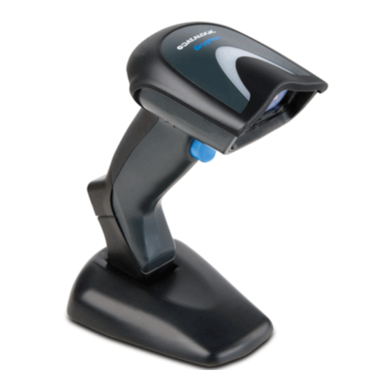
Datalogic GRYPHON Series Reference Manual
Hide thumbs
Also See for GRYPHON Series:
- Quick reference manual (33 pages) ,
- Product reference manual (364 pages) ,
- Product reference manual (333 pages)
Table of Contents
Advertisement
Quick Links
Advertisement
Table of Contents

Subscribe to Our Youtube Channel
Summary of Contents for Datalogic GRYPHON Series
- Page 1 GRYPHON™ Reference Manual...
- Page 3 GRYPHON™ REFERENCE MANUAL...
- Page 4 ALL RIGHTS RESERVED Datalogic reserves the right to make modifications and improvements without prior notification. Datalogic shall not be liable for technical or editorial errors or omissions contained herein, nor for incidental or consequential damages resulting from the use of this material.
-
Page 5: Table Of Contents
CONTENTS GENERAL VIEW ..................viii INTRODUCTION................... 1 INSTALLATION.................... 2 GRYPHON™ D Interface Cable Connections ..........2 OM-GRYPHON™ Interface Cable Connections ........... 3 RS232 Connection..................4 USB....................... 4 IBM USB POS....................5 WEDGE Connection ..................5 PEN Emulation Connection ................6 GRYPHON™... - Page 6 Parity......................31 Data Bits ..................... 31 Stop Bits ..................... 32 Handshaking....................32 ACK/NACK Protocol ................... 33 FIFO......................33 Inter-Character Delay.................. 34 Rx Timeout....................34 Serial Trigger Lock (D Series Only) ............35 USB PARAMETERS .................. 36 Handshaking....................37 Ack/Nack Protocol ..................37 Fifo......................
- Page 7 Field Adjustment Character ................ 65 Code Length Tx ..................65 Character Replacement ................66 Address Stamping (M Series Only)............. 68 Address Delimiter (M Series Only).............. 68 POWER SAVE.................... 69 Scan Rate ....................70 Sleep State ....................70 Enter Sleep Timeout ................... 71 Standby.......................
- Page 8 Code 16K ....................102 Code 49 ....................102 PDF417..................... 103 RSS Codes ....................104 ADVANCED FORMATTING ..............105 Concatenation................... 106 Advanced Formatting................109 RADIO PARAMETERS................124 Radio Protocol Timeout ................125 Power-Off Timeout..................125 Beeper Control for Radio Response ............126 Battery Type....................
- Page 9 Radio Parameters (M Series Only) ............140 5.7.1 Radio Protocol Timeout ................140 5.7.2 Power-Off Timeout..................141 5.7.3 Beeper Control for Radio Response ............141 5.7.4 Single Store ....................141 Configuration Editing Commands ............. 142 Configuration Copying Commands ............143 5.9.1 Copy GRYPHON...
-
Page 10: General View
GENERAL VIEW GRYPHON™ D/M READERS Gryphon™ D Cable Connector Gryphon™ M Battery Cover Trigger Reading Window Figure A – Gryphon™ D and M Series Readers Battery Reconditioning Button LEDs Figure B – OM-GRYPHON™ and C-GRYPHON™ viii... -
Page 11: Introduction
INTRODUCTION INTRODUCTION Datalogic has moved a step ahead in the concept of “instinctive reading. ”The new Gryphon™ reader series has been developed to provide optimised reading performance through excellent ergonomic design, a natural instinctive reading approach and innovative good reading feedback. -
Page 12: Installation
GRYPHON™ INSTALLATION Connections should always be made with power OFF! CAUTION GRYPHON™ D INTERFACE CABLE CONNECTIONS The GRYPHON™ D reader incorporates a multi-standard interface which can be connected to a Host by plugging an RS232, Wedge or Pen emulation cable into the connector as shown below. -
Page 13: Om-Gryphon™ Interface Cable Connections
INSTALLATION OM-GRYPHON™ INTERFACE CABLE CONNECTIONS Multi-standard Interface RS232, WEDGE and PEN Emulation Power OM-GRYPHON™ Connectors The OM-GRYPHON™ incorporates a multi-standard interface which can be connected to a Host by simply plugging an RS232, Wedge or Pen emulation cable into the Host connector, placed on the base of the cradle. -
Page 14: Rs232 Connection
GRYPHON™ RS232 CONNECTION (if required) -
Page 15: Ibm Usb Pos
INSTALLATION IBM USB POS WEDGE CONNECTION... -
Page 16: Pen Emulation Connection
GRYPHON™ PEN EMULATION CONNECTION GRYPHON™ M BATTERY MAINTENANCE 2.8.1 Battery Type You can install NiMh, NiCd or Alkaline AA batteries in the GRYPHON™ M. -
Page 17: Battery Charging
INSTALLATION 2.8.2 Battery Charging Once the system is connected and powered, you can place the GRYPHON™ M into the cradle to charge the battery. When the scanner is correctly inserted in the cradle, the red LED on the cradle goes on to indicate that the battery is charging. - Page 18 GRYPHON™ Open the battery cover. Battery Cover Replace the old batteries with new ones, then screw the battery cover back into place. NiMh, NiCd, or Alkaline AA Batteries Dispose of used batteries properly. Do not disassemble, modify, heat or throw batteries into fire. This could cause leakage of liquid, generation of heat or, in extreme cases, explosion.
-
Page 19: Gryphon™ M System And Network Layouts
GRYPHON™ M SYSTEM AND NETWORK LAYOUTS GRYPHON™ M SYSTEM AND NETWORK LAYOUTS There are two basic system layouts that can be employed: Stand Alone systems and Multidrop STAR-System™ Networks. STAND ALONE LAYOUTS 3.1.1 Single Reader Layout 3.1.2 Multiple Reader Layout In stand alone systems, each cradle is connected to a single Host. -
Page 20: Multiple Stand Alone Layouts
GRYPHON™ 3.1.3 Multiple Stand Alone Layouts Many stand alone connections can operate in the same physical area without interference, provided all readers and cradles in the system have different addresses. Multiple Stand Alone Systems in the Same Area Since the cradles can communicate to multiple GRYPHON™ M scanners, you might find it useful to employ one or more C-GRYPHON™...


Need help?
Do you have a question about the GRYPHON Series and is the answer not in the manual?
Questions and answers