Table of Contents
Advertisement
Quick Links
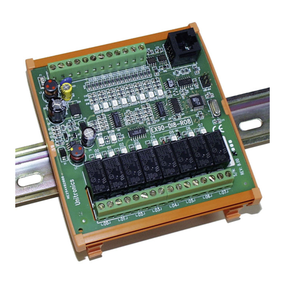
EX90-DI8-RO8
The EX90-DI8-RO8 is an I/O expansion
module that can be used in conjunction
with specific Unitronics OPLC controllers.
The module offers 8 digital inputs, type
pnp (source), and 8 relay outputs.
The EX90-DI8-RO8 is snap-mounted on a
DIN rail.
Component identification
1
Power supply
2
Input connection points
3
OPLC-module communication port
4
Input status indicators
5
Status indicators
6
Output status indicators
7
Output connection points
User safety and equipment protection guidelines
This document is intended to aid trained and competent personnel in the installation of this equipment as defined by
the European directives for machinery, low voltage and EMC. Only a technician or engineer trained in the local and
national electrical standards should perform tasks associated with the electrical wiring of this device.
•
Under no circumstances will Unitronics be liable or responsible for any consequential damage that may arise
as a result of installation or use of this equipment, and is not responsible for problems resulting from improper
or irresponsible use of this device.
•
All examples and diagrams shown in the manual are intended to aid understanding. They do not guarantee
operation.
•
Unitronics accepts no responsibility for actual use of this product based on these examples.
•
Only qualified service personnel should open this device or carry out repairs.
•
Please dispose of this product in accordance with local and national standards and regulations.
•
Check the user program before running it.
•
Do not attempt to use this device with voltage exceeding permissible levels.
•
Install an external circuit breaker and take all appropriate safety measures against short-circuiting in
external wiring.
Unitronics Industrial Automation Systems
I/O Expansion Module
1
24V
0V
00
00
8 Inputs, 8 Outputs
2
I0
I1
I2
I3
I4
I5
I6
I7
I0
I1
I2
I3
I4
I5
I6
I7
5
PWR
RUN
EX90-DI8-RO8
01
02
03
04
05
01
02
03
04
05
7
3
4
06
07
6
06
07
1
Advertisement
Table of Contents

Related Manuals for Unitronics EX90-DI8-RO8


Summary of Contents for Unitronics EX90-DI8-RO8
- Page 1 • Under no circumstances will Unitronics be liable or responsible for any consequential damage that may arise as a result of installation or use of this equipment, and is not responsible for problems resulting from improper or irresponsible use of this device.
- Page 2 Connecting the OPLC to the EX90-DI8-RO8 An OPLC, such as the M90 micro-OPLC, is connected to the EX90-DI8-RO8 as shown below, via a category 5 shielded twisted pair cable (CAT 5, STP), terminated by RJ45 connectors. The cable provided with the EX90-DI8- RO8 is one meter long;...
-
Page 3: Wiring Considerations
4 Tighten enough to keep the wire from pulling free. To avoid damaging the wire, do not exceed a maximum torque of 0.5 N·m (5 kgf·m). • Do not touch live wires. • Double-check all the wiring before turning on the power supply. Unitronics Industrial Automation Systems... - Page 4 High-speed Counter Wiring Outputs The EX90-DI8-RO8 has 8 relay outputs. To increase the life span of these contacts and protect the EX90-DI8-RO8 from potential damage by reverse EMF, connect: • a clamping diode in parallel with each inductive DC load, •...
- Page 5 EX90-DI 8-RO 8 0 8 / 0 0 I / O E x p a n s i o n M o d u l e EX90-DI8-RO8 Technical Specifications Power Supply See Note 1. Input voltage 24VDC Permissible range 20.4 to 28.8VDC Max.
- Page 6 0 8 / 0 0 Notes: Note that both the OPLC and the EX90-DI8-RO8 must be connected to the same power supply. The EX90- DI8-RO8 and the OPLC must be turned on and off simultaneuosly. Input #7 can function either as a high-speed counter, a frequency measurer, or as a normal digital input.
- Page 7 Output #4, located on expansion module #3 in the system, will be addressed as O 84, 84 = 32 + 3 • 16 + 4. EX90-DI8-RO8 is a stand-alone I/O module. Even if it is the only module in the configuration, the EX90-DI8-RO8 is always assigned the number 7.
- Page 8 To order the expansion module that best fits your system, contact your local distributor. For a list of Unitronics distributors, check our website: http://www.unitronic.com/contact.htm...
-
Page 9: Component Identification
All examples and diagrams shown herein are intended to aid understanding, and do not guarantee operation. Unitronics accepts no responsibility for actual use of this product based on these examples. Please dispose of this product in accordance with local and national standards and regulations. -
Page 10: Environmental Considerations
Do not place in water or let water leak onto the unit. Do not allow debris to fall inside the unit during installation. Mounting the Module DIN-rail mounting Snap the device onto the DIN rail as shown below; the module will be squarely situated on the DIN rail. 80mm (3.15") Unitronics... -
Page 11: Screw-Mounting
I / O E x p a n s i o n M o d u l e Screw-Mounting The figure below is not drawn to scale. It may be used as a guide for screw-mounting the module. Mounting screw type: either M3 or NC6-32. 80mm (3.15") 5.8mm 68.4mm (0.228") (2.693") (0.16") 4mm (x2) (0.16") Unitronics... -
Page 12: Connecting Expansion Modules
To avoid damaging the wire, do not exceed a maximum torque of 0.5 N·m (5 kgf·cm). Do not use tin, solder, or any other substance on stripped wire that might cause the wire strand to break. Install at maximum distance from high-voltage cables and power equipment. Unitronics... - Page 13 Allow for voltage drop and noise interference with input lines used over an extended distance. Use wire that is properly sized for the load. Digital Inputs Input wiring Input wiring (top group of inputs) (bottom group of inputs) 110/220 VAC 110/220 VAC Unitronics...
- Page 14 Dimensions (WxHxD) 80mm x 93mm x 60mm (3.15” x 3.66” x 2.362”) Weight 161g (5.7oz.) Mounting Either onto a 35mm DIN-rail or screw- mounted. Notes: The inputs' LEDs light up only when communication link is established between module and OPLC. Unitronics...
- Page 15 Output #4, located on expansion module #3 in the system, will be addressed as O 84, 84 = 32 + 3 • 16 + 4. The maximum number of I/Os varies according to the types of I/O modules linked to the PLC. Unitronics...
- Page 16 Unitronics products referred to herein in any manner deviating from the recommendations made in this document. Unitronics assumes no responsibility for the use of any parts, components, or other ancillary appliances including circuitry other than as recommended hereunder or other than that embodied in the Unitronics product.
- Page 17 All examples and diagrams shown herein are intended to aid understanding, and do not guarantee operation. Unitronics accepts no responsibility for actual use of this product based on these examples. Please dispose of this product in accordance with local and national standards and regulations.
- Page 18 Snap the device onto the DIN rail as shown below; the module will be squarely situated on the DIN rail. 80mm (3.15") Screw-Mounting The figure on the next page is drawn to scale. It may be used as a guide for screw-mounting the module. Mounting screw type: either M3 or NC6-32. Unitronics Industrial Automation...
- Page 19 I O - D I 8 - R O 4 , I O - D I 8 - R O 4 - L I / O E x p a n s i o n M o d u l e s 80mm (3.15") 5.8mm 68.4mm (0.228") (2.693") (0.16") 4mm (x2) (0.16") Unitronics Industrial Automation...
- Page 20 Allow for voltage drop and noise interference with input/output lines used over an extended distance. Use wire that is properly sized for the load. The adapter, input signals, and outputs' power supply must be connected to the same 0V signal. Unitronics Industrial Automation...
- Page 21 110/220VAC to the device’s Circuit Protection Device 0V pin. In the event of voltage fluctuations or Load non-conformity to voltage power supply specifications, connect the device to a Output's regulated power supply. power supply L1, L2, L3 (115/230VAC) +V (12/24VDC) Unitronics Industrial Automation...
- Page 22 Response time 10mSec typical Input #7 The specifications below apply when this input is wired for use as a high-speed counter input/frequency measurer. See Notes 2 and 3. Resolution 16-bit Frequency 5kHz maximum Minimum pulse width 80µs Unitronics Industrial Automation...
- Page 23 When Input #7 is used as a normal digital input, normal input specifications apply. Input #6 can function either as the counter’s reset, or as a normal digital input; in either case, its specifications are those of a normal digital input. Unitronics Industrial Automation...
- Page 24 Unitronics products referred to herein in any manner deviating from the recommendations made in this document. Unitronics assumes no responsibility for the use of any parts, components, or other ancillary appliances including circuitry other than as recommended hereunder or other than that embodied in the Unitronics product.
- Page 25 All examples and diagrams shown herein are intended to aid understanding, and do not guarantee operation. Unitronics accepts no responsibility for actual use of this product based on these examples. Please dispose of this product in accordance with local and national standards and regulations.
- Page 26 Do not place in water or let water leak onto the unit. Do not allow debris to fall inside the unit during installation. Mounting the Module DIN-rail mounting Snap the device onto the DIN rail as shown below; the module will be squarely situated on the DIN rail. 80mm (3.15") Unitronics...
- Page 27 I / O E x p a n s i o n M o d u l e s Screw-Mounting The figure below is not drawn to scale. It may be used as a guide for screw-mounting the module. Mounting screw type: either M3 or NC6-32. 80mm (3.15") 5.8mm 68.4mm (0.228") (2.693") (0.16") 4mm (x2) (0.16") Unitronics...
- Page 28 Input or output cables should not be run through the same multi-core cable or share the same wire. Allow for voltage drop and noise interference with input/output lines used over an extended distance. Use wire that is properly sized for the load. The adapter and I/O signals must be connected to the same 0V signal. Unitronics...
- Page 29 Inputs may be wired as either pnp (source) or npn (sink) inputs. npn (sink) inputs pnp (source) inputs Circuit Protection Device npn (sink) pnp (source ) high-speed counter/frequency measurer high-speed counter/frequency measurer Circuit Protection Device High-speed Counter High-speed Counter High-speed Reset Reset High-speed Counter Counter Unitronics...
- Page 30 Both modules have 8 relay outputs. To increase the life span of these contacts and protect the module from potential damage by reverse EMF, connect: a clamping diode in parallel with each inductive DC load, an RC snubber circuit in parallel with each inductive load. (24VDC) L1, L2, L3 (115/230VAC) Unitronics...
- Page 31 Status Indicators (OUT) Red LEDs—Lit when the corresponding output is active. Contact protection External precautions required (see above: Increasing Contact Life Span) Outputs’ power supply: IO-DI8-RO8 Nominal operating voltage 24VDC Operating voltage 20.4 to 28.8VDC Maximum current consumption 70mA@24VDC Unitronics...
- Page 32 Input #3, located on expansion module #2 in the system, will be addressed as I 67, 67 = 32 + 2 • 16 + 3 Output #4, located on expansion module #3 in the system, will be addressed as O 84, 84 = 32 + 3 • 16 + 4. 5408-0260-7 Unitronics...
- Page 33 All examples and diagrams shown herein are intended to aid understanding, and do not guarantee operation. Unitronics accepts no responsibility for actual use of this product based on these examples. Please dispose of this product in accordance with local and national standards and regulations.
- Page 34 Snap the device onto the DIN rail as shown below; the module will be squarely situated on the DIN rail. 80mm (3.15") Screw-Mounting The figure on the next page is drawn to scale. It may be used as a guide for screw-mounting the module. Mounting screw type: either M3 or NC6-32. Unitronics...
- Page 35 IO - DI8- T O 8, IO - DI8- T O 8- L I / O E x p a n s i o n M o d u l e s 80mm (3.15") 5.8mm 68.4mm (0.228") (2.693") (0.16") 4mm (x2) (0.16") Unitronics...
- Page 36 Input or output cables should not be run through the same multi-core cable or share the same wire. Allow for voltage drop and noise interference with input/output lines used over an extended distance. Use wire that is properly sized for the load. The adapter and I/O signals must be connected to the same 0V signal. Unitronics...
- Page 37 Do not connect the ‘Neutral or ‘Line’ signal of the 110/220VAC to the device’s 0V pin. In the event of voltage fluctuations or non-conformity to voltage power supply specifications, connect the device to a regulated power supply. Unitronics...
- Page 38 Storage temperature -20° to 60° C (-4° to 140°F) Relative Humidity (RH) 5% to 95% (non-condensing) Dimensions (WxHxD) 80mm x 93mm x 60mm (3.15” x 3.66” x 2.362”) Weight 141g (4.9oz.) Mounting Either onto a 35mm DIN-rail or screw- mounted. Unitronics...
- Page 39 Output #4, located on expansion module #3 in the system, will be addressed as O 84, 84 = 32 + 3 • 16 + 4. EX90-DI8-RO8 is a stand-alone I/O module. Even if it is the only module in the configuration, the EX90-DI8-RO8 is always assigned the number 7.
- Page 40 Unitronics website at http://www.unitronics.com/. The information in this document reflects products at the date of printing. Unitronics reserves the right, subject to all applicable laws, at any time, at its sole discretion, and without notice, to discontinue or change the features, designs, materials and other specifications of its products, and to either permanently or temporarily withdraw any of the forgoing from the market.
-
Page 41: I/O Expansion Modules
All examples and diagrams shown herein are intended to aid understanding, and do not guarantee operation. Unitronics accepts no responsibility for actual use of this product based on these examples. Please dispose of this product in accordance with local and national standards and regulations. -
Page 42: Mounting The Module
Snap the device onto the DIN rail as shown below; the module will be squarely situated on the DIN rail. 80mm (3.15") Screw-Mounting The figure on the next page is drawn to scale. It may be used as a guide for screw-mounting the module. Mounting screw type: either M3 or NC6-32. Unitronics Industrial Automation... - Page 43 I O - D I 1 6 , I O - D I 1 6 - L I / O E x p a n s i o n M o d u l e s 80mm (3.15") 5.8mm 68.4mm (0.228") (2.693") (0.16") 4mm (x2) (0.16") Unitronics Industrial Automation...
-
Page 44: Connecting Expansion Modules
Allow for voltage drop and noise interference with input lines used over an extended distance. Use wire that is properly sized for the load. The adapter and input signals must be connected to the same 0V signal. Unitronics Industrial Automation... - Page 45 10 1 1 12 13 1 4 1 5 I9 I10 I11 I12 I13 I14 I15 pnp (source) High-speed Reset Counter I10 I11 I12 I13 I14 I15 High-speed Counter pnp (source) input wiring (shown in bottom group of inputs) Unitronics Industrial Automation...
- Page 46 When Input #15 is used as a normal digital input, normal input specifications apply. Input #14 can function either as the counter’s reset, or as a normal digital input; in either case, its specifications are those of a normal digital input. Unitronics Industrial Automation...
- Page 47 Output #4, located on expansion module #3 in the system, will be addressed as O 84, 84 = 32 + 3 • 16 + 4. EX90-DI8-RO8 is a stand-alone I/O module. Even if it is the only module in the configuration, the EX90-DI8- RO8 is always assigned the number 7.
- Page 48 Unitronics products referred to herein in any manner deviating from the recommendations made in this document. Unitronics assumes no responsibility for the use of any parts, components, or other ancillary appliances including circuitry other than as recommended hereunder or other than that embodied in the Unitronics product.
-
Page 49: Relay Outputs
All examples and diagrams shown herein are intended to aid understanding, and do not guarantee operation. Unitronics accepts no responsibility for actual use of this product based on these examples. Please dispose of this product in accordance with local and national standards and regulations. - Page 50 Snap the device onto the DIN rail as shown below; the module will be squarely situated on the DIN rail. 80mm (3.15") Screw-Mounting The figure on the next page is drawn to scale. It may be used as a guide for screw-mounting the module. Mounting screw type: either M3 or NC6-32. Unitronics Industrial Automation...
- Page 51 I O - R O 8 , I O - R O 8 L I / O E x p a n s i o n M o d u l e 80mm (3.15") 5.8mm 68.4mm (0.228") (2.693") (0.16") 4mm (x2) (0.16") Unitronics Industrial Automation...
- Page 52 Allow for voltage drop and noise interference with input/output lines used over an extended distance. Use wire that is properly sized for the load. The adapter and module’s power supply must be connected to the same 0V signal. Unitronics Industrial Automation...
- Page 53 EMF, connect: a clamping diode in parallel with each inductive DC load, an RC snubber circuit in parallel with each inductive load. L1, L2, L3 (12/24VDC) (115/230VAC) Unitronics Industrial Automation...
- Page 54 -20° to 60° C (-4 to 140°F) Relative Humidity (RH) 5% to 95% (non-condensing) Dimensions (WxHxD) 80mm x 93mm x 60mm (3.15” x 3.66” x 2.362”) Weight 183g (6.45 oz.) Mounting Either onto a 35mm DIN-rail or screw- mounted. Unitronics Industrial Automation...
- Page 55 Output #4, located on expansion module #3 in the system, will be addressed as O 84, 84 = 32 + 3 • 16 + 4. EX90-DI8-RO8 is a stand-alone I/O module. Even if it is the only module in the configuration, the EX90-DI8- RO8 is always assigned the number 7.
- Page 56 Unitronics products referred to herein in any manner deviating from the recommendations made in this document. Unitronics assumes no responsibility for the use of any parts, components, or other ancillary appliances including circuitry other than as recommended hereunder or other than that embodied in the Unitronics product.
- Page 57 All examples and diagrams shown herein are intended to aid understanding, and do not guarantee operation. Unitronics accepts no responsibility for actual use of this product based on these examples. Please dispose of this product in accordance with local and national standards and regulations.
- Page 58 Snap the device onto the DIN rail as shown below; the module will be squarely situated on the DIN rail. 80mm (3.15") Screw-Mounting The figure on the next page is drawn to scale. It may be used as a guide for screw-mounting the module. Mounting screw type: either M3 or NC6-32. Unitronics Industrial Automation...
- Page 59 5/03 IO - RO 16, IO -RO 16-L I / O E x p a n s i o n M o d u l e s 80mm (3.15") 5.8mm 68.4mm (0.228") (2.693") (0.16") 4mm (x2) (0.16") Unitronics Industrial Automation...
- Page 60 To avoid damaging the wire, do not exceed a maximum torque of 0.5 N·m (5 kgf·m). Do not use tin, solder, or any other substance on stripped wire that might cause the wire strand to break. Install at maximum distance from high-voltage cables and power equipment. Unitronics Industrial Automation...
- Page 61 DC load, as shown in the left-hand figure below. an RC snubber circuit in parallel with each inductive load, as shown in the right-hand figure below.. (12/24VDC) L1, L2, L3 115/230VAC Unitronics Industrial Automation...
- Page 62 -20° to 60° C (-4° to 140°F) Relative Humidity (RH) 5% to 95% (non-condensing) Dimensions (WxHxD) 80mm x 93mm x 60mm (3.15” x 3.66” x 2.362”) 125g (4.25 oz.) Weight Mounting Either onto a 35mm DIN-rail or screw- mounted. Unitronics Industrial Automation...
- Page 63 Output #4, located on expansion module #3 in the system, will be addressed as O 84, 84 = 32 + 3 • 16 + 4. EX90-DI8-RO8 is a stand-alone I/O module. Even if it is the only module in the configuration, the EX90-DI8- RO8 is always assigned the number 7.
- Page 64 Unitronics products referred to herein in any manner deviating from the recommendations made in this document. Unitronics assumes no responsibility for the use of any parts, components, or other ancillary appliances including circuitry other than as recommended hereunder or other than that embodied in the Unitronics product.
-
Page 65: Transistor Outputs
Under no circumstances will Unitronics be liable or responsible for any consequential damage that may arise as a result of installation or use of this equipment, and is not responsible for problems resulting from improper or irresponsible use of this device. -
Page 66: Mounting Considerations
Snap the device onto the DIN rail as shown below; the module will be squarely situated on the DIN rail. 80mm Screw-Mounting The figure on the next page is drawn to scale. It may be used as a guide for screw-mounting the module. Mounting screw type: either M3 or NC6-32. Unitronics Industrial Automation Systems... - Page 67 IO -T O 16 1 1 / 0 0 I / O E x p a n s i o n M o d u l e 80mm 68.4mm 5.8mm 4mm (x2) Unitronics Industrial Automation Systems...
- Page 68 Input or output cables should not be run through the same multi-core cable or share the same wire. Allow for voltage drop and noise interference with output lines used over an extended distance. Use wire that is properly sized for the load. Unitronics Industrial Automation Systems...
- Page 69 In the event of voltage fluctuations or non-conformity to voltage power supply specifications, connect the device to a regulated power supply. 24VDC power supply for 1st group of outputs Circuit Load Protection Device Circuit Protection Load Device 24VDC power supply for 2nd group of outputs Unitronics Industrial Automation Systems...
- Page 70 Within the M90 OPLC, for example, SB 5 turns ON. SI 5 contains a bitmap indicating the module containing the affected output. For more information, refer to the on-line help supplied with the programming package of your controller. Unitronics Industrial Automation Systems...
- Page 71 Output #4, located on expansion module #3 in the system, will be addressed as O 84, 84 = 32 + 3 • 16 + 4. EX90-DI8-RO8 is a stand-alone I/O module. Even if it is the only module in the configuration, the EX90-DI8- RO8 is always assigned the number 7.
Need help?
Do you have a question about the EX90-DI8-RO8 and is the answer not in the manual?
Questions and answers