Table of Contents
Advertisement
Quick Links
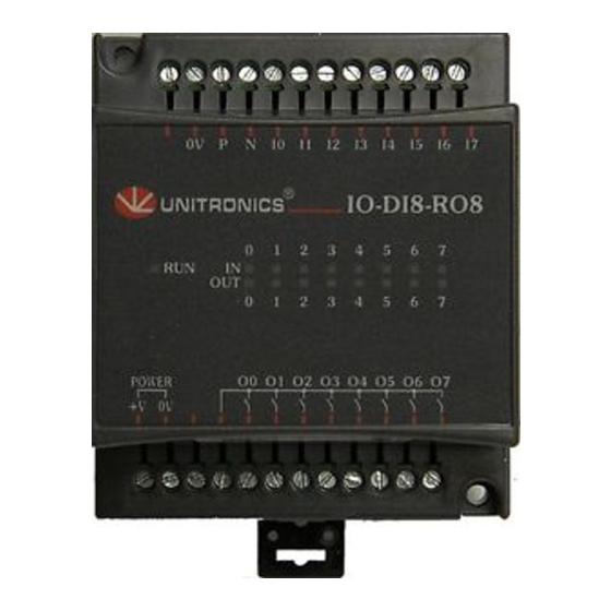
IO-DI8-RO8, IO-DI8-RO8-L
The IO-DI8-RO8 and IO-DI8-RO8-L are I/O
expansion modules that can be used in
conjunction with specific Unitronics OPLC
controllers.
The modules are identical except for their
voltage specifications: IO-DI8-RO8 runs at
24 VDC; IO-DI8-RO8-L at 12 VDC.
Both modules offer 8 digital inputs, type
pnp/npn (source/sink), and 8 relay outputs.
The interface between a module and the
OPLC is provided by an adapter.
These modules may either be snap-
mounted on a DIN rail, or screw-mounted
onto a mounting plate.
Component identification
1
Module-to-module connector
2
Status indicators
3
Connection points for power
supply to outputs
4
Output connection points
5
Module-to-module connector port
6
Input connection points
Before using this product, it is the responsibility of the user to read and understand this document and any
accompanying documentation.
All examples and diagrams shown herein are intended to aid understanding, and do not guarantee
operation. Unitronics accepts no responsibility for actual use of this product based on these examples.
Please dispose of this product in accordance with local and national standards and regulations.
Only qualified service personnel should open this device or carry out repairs.
User safety and equipment protection guidelines
This document is intended to aid trained and competent personnel in the installation of this equipment as
defined by the European directives for machinery, low voltage, and EMC. Only a technician or engineer trained
in the local and national electrical standards should perform tasks associated with the device's electrical wiring.
Symbols are used to highlight
information relating to the user's
personal safety and equipment
protection throughout this document.
When these symbols appear, the
associated information must be read
carefully and understood fully.
Failure to comply with appropriate safety guidelines can result in severe personal injury or
property damage. Always exercise proper caution when working with electrical equipment.
Unitronics
I/O Expansion Modules 8 Inputs, 8 Outputs
1
2
3
Symbol
Meaning
Danger
Warning
Caution
Caution
Description
The identified danger causes physical
and property damage.
The identified danger can cause
physical and property damage.
Use caution.
6
5
4
1
Advertisement
Table of Contents

Subscribe to Our Youtube Channel
Related Manuals for Unitronics IO-DI8-RO8-L


Summary of Contents for Unitronics IO-DI8-RO8-L
- Page 1 All examples and diagrams shown herein are intended to aid understanding, and do not guarantee operation. Unitronics accepts no responsibility for actual use of this product based on these examples. Please dispose of this product in accordance with local and national standards and regulations.
-
Page 2: Environmental Considerations
Do not place in water or let water leak onto the unit. Do not allow debris to fall inside the unit during installation. Mounting the Module DIN-rail mounting Snap the device onto the DIN rail as shown below; the module will be squarely situated on the DIN rail. 80mm (3.15") Unitronics... -
Page 3: Screw-Mounting
I / O E x p a n s i o n M o d u l e s Screw-Mounting The figure below is not drawn to scale. It may be used as a guide for screw-mounting the module. Mounting screw type: either M3 or NC6-32. 80mm (3.15") 5.8mm 68.4mm (0.228") (2.693") (0.16") 4mm (x2) (0.16") Unitronics... -
Page 4: Connecting Expansion Modules
Input or output cables should not be run through the same multi-core cable or share the same wire. Allow for voltage drop and noise interference with input/output lines used over an extended distance. Use wire that is properly sized for the load. The adapter and I/O signals must be connected to the same 0V signal. Unitronics... - Page 5 Inputs may be wired as either pnp (source) or npn (sink) inputs. npn (sink) inputs pnp (source) inputs Circuit Protection Device npn (sink) pnp (source ) high-speed counter/frequency measurer high-speed counter/frequency measurer Circuit Protection Device High-speed High-speed Counter Counter Reset High-speed High-speed Reset Counter Counter Unitronics...
- Page 6 Both modules have 8 relay outputs. To increase the life span of these contacts and protect the module from potential damage by reverse EMF, connect: a clamping diode in parallel with each inductive DC load, an RC snubber circuit in parallel with each inductive load. (24VDC) L1, L2, L3 (115/230VAC) Unitronics...
- Page 7 Input type pnp (source) or npn (sink) Galvanic isolation None Green LEDs—Lit when the corresponding input is active. See Note 1. Status indicators(IN) 24VDC for IO-DI8-RO8, 12VDC for IO-DI8-RO8-L Nominal input voltage Input voltage IO-DI8-RO8 IO-DI8-RO8-L pnp (source) 0-5VDC for Logic ‘0’...
- Page 8 I O - D I 8 - R O 8 , I O - D I 8 - R O 8 - L 5 / 0 5 I / O E x p a n s i o n M o d u l e s Outputs’ power supply: IO-DI8-RO8-L Nominal operating voltage 12VDC Operating voltage 10.2 to 15.6VDC...
Need help?
Do you have a question about the IO-DI8-RO8-L and is the answer not in the manual?
Questions and answers