Table of Contents
Advertisement
Quick Links
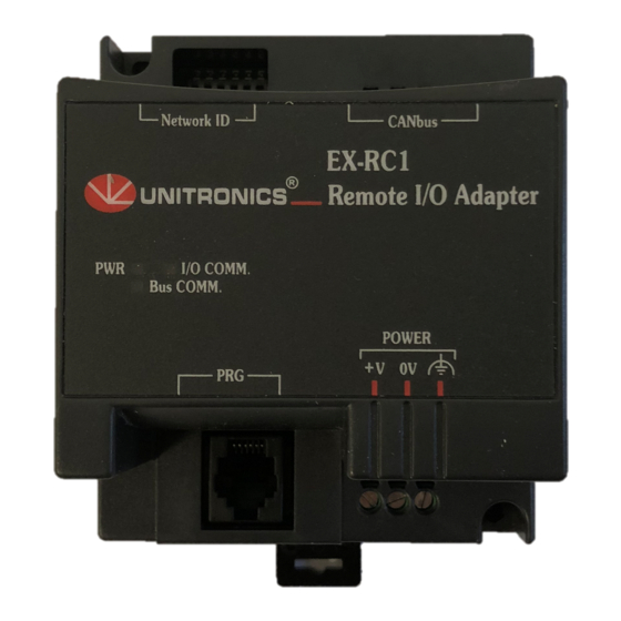
EX-RC1
Remote I/O Adapter
The EX-RC1 interfaces between Unitronics Vision OPLCs and remote I/O Expansion Modules distributed
throughout your system.
The adapter is connected to a PLC via CANbus. Each adapter may be connected to up to 8 I/O Expansion
Modules. The network may comprise up to 60 nodes, including both PLCs and adapters; note that the PLC must
comprise a CANbus port. Communication is via UniCAN, Unitronics' proprietary CANbus protocol.
The EX-RC1 is run by a factory-installed application. The adapter can auto-detect digital I/O Expansion
Modules. If the system includes analog modules, the application must be edited. For more information refer to
the Remote I/O topics in the VisiLogic Help system.
The EX-RC1 may either be snap-mounted
on a DIN rail, or screw-mounted onto a
mounting plate.
Component identification
1
Status indicators
2
PC to EX-RC1 connection port
3
Power supply connection points
4
EX-RC1 to expansion module
connection port
5
CANbus port
6
DIP Switches
◼
Before using this product, it is the responsibility of the user to read and understand this document and
any accompanying documentation.
◼
All examples and diagrams shown herein are intended to aid understanding, and do not guarantee
operation. Unitronics accepts no responsibility for actual use of this product based on these examples.
◼
Please dispose of this product in accordance with local and national standards and regulations.
◼
Only qualified service personnel should open this device or carry out repairs.
User safety and equipment protection guidelines
This document is intended to aid trained and competent personnel in the installation of this equipment as
defined by the European directives for machinery, low voltage, and EMC. Only a technician or engineer trained
in the local and national electrical standards should perform tasks associated with the device's electrical wiring.
Symbols are used to highlight
information relating to the user's
personal safety and equipment
protection throughout this document.
When these symbols appear, the
associated information must be read
carefully and understood fully.
◼
Failure to comply with appropriate safety guidelines can result in severe personal injury or
property damage. Always exercise proper caution when working with electrical equipment.
◼
Check the user program before running it.
◼
Do not attempt to use this device with parameters that exceed permissible levels.
◼
Install an external circuit breaker and take appropriate safety measures against short-circuiting
in external wiring.
◼
To avoid damaging the system, do not connect / disconnect the device when the power is on.
Unitronics
User Guide
6
Network ID
1
PWR
I/O COMM.
Bus COMM.
PRG
2
Symbol
Meaning
Danger
Warning
Caution
Caution
5
CANbus
EX-RC1
Remote I/O Adapter
POWER
V
0V
3
Description
The identified danger causes physical
and property damage.
The identified danger can cause
physical and property damage.
Use caution.
4
1
Advertisement
Table of Contents

Related Manuals for Unitronics EX-RC1


Summary of Contents for Unitronics EX-RC1
- Page 1 CANbus port. Communication is via UniCAN, Unitronics’ proprietary CANbus protocol. The EX-RC1 is run by a factory-installed application. The adapter can auto-detect digital I/O Expansion Modules. If the system includes analog modules, the application must be edited. For more information refer to the Remote I/O topics in the VisiLogic Help system.
- Page 2 Leave a minimum of 10mm space for ventilation between the top and bottom edges of the device and the enclosure walls. ◼ Do not place in water or let water leak onto the unit. ◼ Do not allow debris to fall inside the unit during installation. Unitronics...
- Page 3 Class I, Division 2, Groups A, B, C et D. Cette note fait référence à tous les produits Unitronics portant le symbole UL - produits qui ont été certifiés pour une utilisation dans des endroits dangereux, Classe I, Division 2, Groupes A, B, C et D.
- Page 4 Snap the device onto the DIN rail as shown below; the module will be squarely situated on the DIN rail. Screw-Mounting The figure below is not drawn to scale. It may be used as a guide for screw-mounting the module. Mounting screw type: either M3 or NC6-32. 80mm (3.15") 5.8mm 68.4mm (0.228") (2.693") (0.16") 4mm (x2) (0.16") Unitronics...
- Page 5 To avoid damaging the wire, do not exceed a maximum torque of 0.5 N·m (5 kgf·cm). ◼ Do not use tin, solder, or any other substance on stripped wire that might cause the wire strand to break. ◼ Install at maximum distance from high-voltage cables and power equipment. Unitronics...
- Page 6 ◼ Earthing the module’s power supply: connect one end of a 14 AWG wire to the chassis signal; connect the other end to the panel. Note: If possible, the wire used to earth the power supply should not exceed 10 cm in length. However, it is recommended to earth the module in all cases. POWER Unitronics...
- Page 7 CANbus Connector terminating resistor Network Layout The EX-RC1 enables you to remotely locate I/Os up to 1 kilometer from a PLC. You can include both PLCs and adapters on the UniCAN network, up to a total of 60 nodes. Unitronics...
- Page 8 Either onto a 35mm DIN-rail or screw-mounted. The information in this document reflects products at the date of printing. Unitronics reserves the right, subject to all applicable laws, at any time, at its sole discretion, and without notice, to discontinue or change the features, designs, materials and other specifications of its products, and to either permanently or temporarily withdraw any of the forgoing from the market.
Need help?
Do you have a question about the EX-RC1 and is the answer not in the manual?
Questions and answers