Advertisement
V200-18-E62B
The V200-18-E62B
plugs directly into the
back of compatible
Unitronics OPLCs,
creating a self-
contained PLC unit with
a local I/O
configuration.
▪ Before using this product, it is the responsibility of the user to read and understand this document and
any accompanying documentation.
▪ All examples and diagrams shown herein are intended to aid understanding, and do not guarantee
operation. Unitronics accepts no responsibility for actual use of this product based on these examples.
▪ Please dispose of this product in accordance with local and national standards and regulations.
▪ Only qualified service personnel should open this device or carry out repairs.
User safety and equipment protection guidelines
This document is intended to aid trained and competent personnel in the installation of this equipment as defined
by the European directives for machinery, low voltage, and EMC. Only a technician or engineer trained in the
local and national electrical standards should perform tasks associated with the device's electrical wiring.
Symbols are used to highlight
information relating to the user's
personal safety and equipment
protection throughout this document.
When these symbols appear, the
associated information must be read
carefully and understood fully.
▪ Failure to comply with appropriate safety guidelines can result in severe personal injury or
property damage. Always exercise proper caution when working with electrical
equipment.
▪ Check the user program before running it.
▪ Do not attempt to use this device with parameters that exceed permissible levels.
▪ Install an external circuit breaker and take appropriate safety measures against short-
circuiting in external wiring.
▪ To avoid damaging the system, do not connect / disconnect the device when the power is
on.
▪ Ascertain that terminal blocks are properly secured in place.
Caution
Environmental Considerations
▪ Do not install in areas with: excessive or conductive dust, corrosive or flammable gas,
moisture or rain, excessive heat, regular impact shocks or excessive vibration.
▪ Provide proper ventilation by leaving at least 10mm of space between the top and bottom
edges of the device and the enclosure walls.
▪ Do not place in water or let water leak onto the unit.
▪ Do not allow debris to fall inside the unit during installation.
UL Compliance
The following section is relevant to Unitronics' products that are listed with the UL.
The following models: V200-18-E1B, V200-18-E2B, V200-18-E6B, V200-18-E6BL
are UL listed for Hazardous Locations.
The following models: V200-18-E1B, V200-18-E2B, V200-18-E3B, V200-18-E3XB, V200-18-E46B,
V200-18-E46BL, V200-18-E4B, V200-18-E4XB,
V200-18-E5B, V200-18-E6B, V200-18-E6BL, V200-18-ECB, V200-18-ECXB, V200-18-ESB
are UL listed for Ordinary Location.
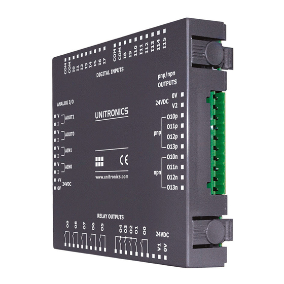
Unitronics
Snap-in I/O Module
Features
▪ 30 isolated digital inputs configurable to type pnp/npn (source/sink),
includes 2 shaft encoder inputs.
▪ 28 isolated pnp outputs.
▪ 2 isolated pnp/npn (source/sink) transistor outputs, includes
2 high-speed outputs.
▪ 2 analog inputs.
Symbol
Caution
Meaning
Description
The identified danger causes physical
Danger
and property damage.
The identified danger can cause
Warning
physical and property damage.
Caution
Use caution.
1
Advertisement
Table of Contents

Subscribe to Our Youtube Channel
Related Manuals for Unitronics V200-18-E62B


Summary of Contents for Unitronics V200-18-E62B
- Page 1 ▪ All examples and diagrams shown herein are intended to aid understanding, and do not guarantee operation. Unitronics accepts no responsibility for actual use of this product based on these examples. ▪ Please dispose of this product in accordance with local and national standards and regulations.
- Page 2 Class I, Division 2, Groups A, B, C et D. Cette note fait référence à tous les produits Unitronics portant le symbole UL - produits qui ont été certifiés pour une utilisation dans des endroits dangereux, Classe I, Division 2, Groupes A, B, C et D.
- Page 3 To maximize system performance, avoid electromagnetic interference as follows: ▪Use a metal cabinet. ▪Connect the 0V and functional ground points (if exist) directly to the earth ground of the system. ▪Use the shortest, less than 1m (3.3 ft.) and thickest, 2.08mm² (14AWG) min, wires possible. Unitronics...
-
Page 4: Digital Inputs
(sink) digital input wiring pnp (source) digital input wiring npn (sink) high-speed counter pnp (source) high-speed counter Inputs I0, I1, and I2, I3 can be used as shaft encoders as shown below. npn (sink) shaft encoder wiring pnp (source) shaft encoder wiring Unitronics... -
Page 5: Digital Outputs
Open the device and set the jumpers according to the instructions beginning on page 6. ▪ Outputs 2 to 29 function as pnp only. ▪ The 0V signal of the transistor outputs is isolated from the controller’s 0V signal. npn (sink) pnp (source) Unitronics... -
Page 6: Analog Inputs
2. Gently rock the module from side to side, easing the module from the controller. 3. Using a Philips screwdriver, remove the center screw from the module’s PCB board. Unitronics... - Page 7 Next, reinstall the module. Line the circular guidelines on the controller up with the guidelines on the Snap-in I/O Module as shown below. Apply even pressure on all 4 corners until you hear a distinct ‘click’. The module is now installed. Check that all sides and corners are correctly aligned. Unitronics...
- Page 8 UG_V200-18-E6B Snap-in I/O Module 12/22 V200-18-E62B Technical Specifications Digital Inputs Number of inputs 30 (in 3 groups) Input type pnp (source) or npn (sink) Galvanic isolation Digital inputs to bus Digital inputs to digital inputs in same group Group to group, digital inputs...
- Page 9 ±30mA, 15V—current Full-scale error ±3 LSB (0.3%) Linearity error ±3 LSB (0.3%) Status indication Yes. See Note 7. Notes: Inputs AN0 and AN1 may be wired to work with either current or voltage. The analog value can indicate a fault: Unitronics...
- Page 10 The tradenames, trademarks, logos and service marks presented in this document, including their design, are the property of Unitronics (1989) (R"G) Ltd. or other third parties and you are not permitted to use them without the prior written consent of Unitronics or such third party as may own them UG_V200-18-E62B.pdf...
Need help?
Do you have a question about the V200-18-E62B and is the answer not in the manual?
Questions and answers