Table of Contents
Advertisement
Quick Links
Advertisement
Table of Contents

Related Manuals for Hyundai HPC-250HT


Summary of Contents for Hyundai HPC-250HT
- Page 1 HPC-250HT Photovoltaic Inverter User Manual...
-
Page 2: Table Of Contents
HPC-250HT User Interface ......................10 3.2.5 Light Indicators (-H1, -H2) ......................11 ..........................11 PERATING ODES 3.3.1 Operating Modes of the HPC-250HT ..................... 12 3.3.1.1 Automatic Startup ........................... 12 3.3.1.2 Waiting after Grid Failure ........................13 3.3.1.3 Testing of String Voltage ........................14 3.3.1.4... - Page 3 USER MANUAL of HPC-250HT COMMUNICATION ..........................57 ..................57 NTERING OR HANGING MAIL DDRESSES ..................... 59 ELECTING THE EPORT YPES TO ........................60 ENDING A MAIL FAULTS ..............................63 ..........................63 AULT IAGNOSTICS 7.1.1 Types of Faults ..........................63 7.1.1.1 Emergencies ............................
-
Page 4: Notes On This Manual
1 Notes on this Manual 1.1 Target Group and Applicability The purpose of this manual is to be an aid for HPC-250HT installers and operators in installing, operating, maintenance and troubleshooting of the HPC-250HT Photovoltaic Inverter. It serves as a rule regarding the operation of the HPC-250HT and User Interface, and applies for UI software version 1.0. -
Page 5: Safety Instructions
All actions during installation, operation, troubleshooting and maintenance or any other cause have to be carried out by qualified and trained technician! All actions described in this manual that are performed on the HPC-250HT have to be carried out as described in the following sections of this user manual. -
Page 6: Description Of The Hpc-250Ht
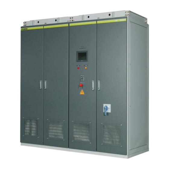
USER MANUAL of HPC-250HT 3 Description of the HPC-250HT The HPC-250HT is a photovoltaic inverter cabinet for converting solar energy generated by photovoltaic power modules to three phase, sinusoidal, low level voltages and currents, ready to be fed back to the utility grid. -
Page 7: Ac Side Rotary Handle Circuit Breaker
Start / Stop key operated switch. The HPC-250HT connects to the utility grid by means of an AC Circuit Breaker. If manually turned to the “Off” position the circuit breaker isolates the AC contactor (-K1), AC EMC filter (-A12), transformer (-T1), LC filter capacitor (C1…18) and inductor (-T2) and the 3ph inverter... -
Page 8: Emergency-Off Button (-S2)
Emergency button. Always bear in mind that not all of the internal components of the HPC-250HT cabinet are isolated from their power supply, the AC utility grid or the DC network of solar panels after exerting the Emergency-Off Button (-S2). -
Page 9: Start / Stop Key Operated Spring-Return Switch (-S1)
“Waiting after Grid Failure” state. Each time the utility grid voltage is disconnected from the HPC-250HT or the power supply is disconnected from the MCU of the HPC-250HT, the system waits for additional five minutes... -
Page 10: Hpc-250Ht User Interface
USER MANUAL of HPC-250HT 3.2.4 HPC-250HT User Interface The HPC-250HT operation can be observed and the system settings may be modified by means of the HPC-250HT User Interface. Control, monitoring, reporting and administrative functions can be exercised, observed and altered using the UI residing at the front of the AC side cabinet (-E2). -
Page 11: Light Indicators (-H1, -H2)
3.2.5 Light Indicators (-H1, -H2) In case of a fault during operation of the HPC-250HT, the type of the occurred fault is being indicated via a red and a yellow light on the front of the AC side cabinet (-E2) of the HPC- 250HT cubicle. -
Page 12: Operating Modes Of The Hpc-250Ht
The system initiates an automatic startup only 5 minutes after connecting the auxiliary power supply to the MCU of the HPC-250HT. The system is not detecting trip utility network – related trip events, but emergency and warning events are redirected to the MCU. -
Page 13: Waiting After Grid Failure
USER MANUAL of HPC-250HT 3.3.1.2 Waiting after Grid Failure Each time the utility grid voltage is disconnected from the HPC-250HT or the power supply is disconnected from the MCU of the HPC-250HT, the system waits for additional five minutes counting from the reconnection of the MCU power supply or counting from the moment in which the stable condition of the utility network has been met, respectively, before the HPC- 250HT is allowed to connect to the utility grid again. -
Page 14: Testing Of String Voltage
3.3.1.3 Testing of String Voltage In thi state the HPC-250HT ascertains the sufficient level of DC voltage. This check is performed by measuring the DC voltage level at the DC power input of the HPC-250HT until sufficient DC voltage vs. time area was measured. -
Page 15: Grid Voltage And Frequency Test
During this step several measurements are undertaken to safely decide the operating conditions of the utility grid the HPC-250HT cabinet is connected to. Only after the connected utility grid is in stable state - with its key properties within standard-defined ranges - may the HPC-250HT proceed with preparations of grid connection. -
Page 16: Connecting To Solar Arrays
The system switches to ”Testing of String Voltage” state if the utility grid operation conditions set on the “Setting 2” tab page are met and the HPC-250HT did not perform a regular low-power shut down, or, the “Wait Time” accessible on the “Setting 1”... -
Page 17: Connecting To Grid, Test Of String Voltage
The output power delivery capability of the network of solar arrays is tested in this step of the HPC-250HT start sequence. The network of solar arrays is loaded and input voltage drop is measured. The measured voltage level (factory-determined voltage level, always below the value set in the “Start Voltage”... -
Page 18: Feeding To The Grid (4)
AC Contactor (-K1) are energized and are operating on the same voltage and frequency levels, therefore assuring a zero-current switch on of the contactor. After successful completion of the start sequence the state of the HPC-250HT changes to “Feeding to the Grid”, the system behaves according to the Maximum Power Point and “Maximum Output Power”... - Page 19 USER MANUAL of HPC-250HT The system can get into this state If the measured input voltage level of the HPC-250HT during the String Voltage Test is above a factory-set safety value, the AC Contactor (-K1) turns ON, the system connects to the utility network and system state switches to “Feeding to the Grid”...
-
Page 20: Shut Down (5)
USER MANUAL of HPC-250HT 3.3.1.8 Shut Down (5) The system or the user initiates and performs a regular shut down sequence consisting of actual system-state-defined steps, if one of the following requirements is met. The system can get into this state If the Start / Stop Key Operated Spring-return Switch (-S1) is operated and held in the “Stop”... -
Page 21: Disconnecting From Grid
USER MANUAL of HPC-250HT 3.3.1.9 Disconnecting from Grid This step of the shut down sequence disconnects the HPC-250HT from the utility grid by turning OFF the AC Contactor (-K1). The system can get into this state From “Shut Down” state, after an automatic shutdown process was initiated, meaning that the input DC power of the HPC250-HT is lower than the threshold value set in the “Stop Power”... -
Page 22: Offline
USER MANUAL of HPC-250HT 3.3.1.10 Offline The HPC-250HT is deactivated and resides in this state until the Start / Stop Key Operated Spring-Return Switch (-S1) is turned to “Start” position for at least three seconds to maneuver the HPC-250HT into “Wait” mode. -
Page 23: Hpc-250Ht Control Operation
USER MANUAL of HPC-250HT 4 HPC-250HT Control Operation The HPC-250HT User Interface is mounted on the front door of the -E2 cubicle of the cabinet. It is operated by tapping on the screen with the designated touch panel operating pen. Make sure to only use the designated touch panel operating pen to operate the touch screen of the User Interface. - Page 24 USER MANUAL of HPC-250HT The completion of the main initialization is indicated by the illumination of the User Interface and a LED indicator lighting up at the left side of the User Interface. The screen of the User Interface can be divided into three sections as displayed on the...
-
Page 25: Overview Of The Menu
USER MANUAL of HPC-250HT 4.2 Overview of the Menu The HPC-250HT User Interface consists of altogether nine pages, each of them subdivided into categories which contain system information accessible by the system operator. To choose and switch between the menu pages one has to tap the name of the menu on the tab page selector and the display automatically changes to the selected menu screen. -
Page 26: Online Info (Brief Description)
USER MANUAL of HPC-250HT 4.2.2 Online Info (Brief Description) Menu Page Category System information Online Info Status bar System Time, System Date, System Status, Operator Status Online Info Total Energy Grid Power Grid Voltage Grid Current PV Power PV Voltage... -
Page 27: Fault Handling (Brief Description)
USER MANUAL of HPC-250HT 4.2.3 Fault Handling (Brief Description) Menu Page Category System information Fault Handling Emergency Emergency Information, Emergency Acknowledgement Trip Trip Information, Trip Acknowledgement Alarm Alarm Information, Alarm Acknowledgement PE07019-022-B Page 27 of 69... -
Page 28: Log (Brief Description)
USER MANUAL of HPC-250HT 4.2.4 Log (Brief Description) Menu Page Category System information Fault List Show Fault list content Start / Stop List Show Start / Stop list content Tech. Event List Show Technical Event list content PE07019-022-B Page 28 of 69... -
Page 29: System (Brief Description)
USER MANUAL of HPC-250HT 4.2.5 System (Brief Description) Menu Page Category System information System Status bar System Date, System Status, Operator Status System Information On Time Last Start Time System Started Emergency Counter Trip Counter Alarm Counter PVC Communication Report Sending... -
Page 30: Email (Brief Description)
USER MANUAL of HPC-250HT 4.2.6 Email (Brief Description) Menu Page Category System information Email Email Settings Email Sender Email Receiver Email Server IP Email Server Port Test Email Send Test Email Email State Email Progress Email Sending State PE07019-022-B Page 30 of 69... -
Page 31: Operator (Brief Description)
USER MANUAL of HPC-250HT 4.2.7 Operator (Brief Description) Menu Page Category System information Operator Equipment Test Turn ON DC Circuit Breaker (-Q1) Turn OFF DC Circuit Breaker(-Q1) Turn ON/OFF Red and Yellow Indicator Lights Control Power ON Control Power OFF... -
Page 32: Setting 1 (Brief Description)
USER MANUAL of HPC-250HT 4.2.8 Setting 1 (Brief Description) Menu Page Category System information Setting 1 Change Time and Date New System Year, Month, Date, Hour, Minute Start/Stop Condition Start Voltage, Start Time, Stop Power, Stop Time Wait Time PE07019-022-B... -
Page 33: Setting 2 (Brief Description)
USER MANUAL of HPC-250HT 4.2.9 Setting 2 (Brief Description) Menu Page Category System information Test Grid Nominal Values Nominal Grid Voltage Nominal Grid Frequency Grid Voltage Limits Maximal Grid Voltage Minimal Grid Voltage Grid Frequency Limits Maximum Output Power Output Power Limitaton Turn Ratio and LCK Nr. -
Page 34: Start (Detailed Description)
4.2.10 Start (Detailed Description) The “Start” tab page is the first page of the HPC-250HT User Interface. The “Start” tab page displays the HPC-250HT “Serial Number” and the “User Interface version number” together with the actual date and time, system operator status and the RS485 based external data acquisition system communication speed setting. -
Page 35: Online Info (Detailed Description)
AC power filter choke [-T2] and the highest temperature occurring inside the three IGBT bridges. By tapping the “Start MPP Scan” button the HPC-250HT initiates an MPP Scan cycle in case the actual system state does not exclude its initiation. To perform an MPP Scan cycle is only possible from “Feeding to the Grid”... - Page 36 USER MANUAL of HPC-250HT The “MPP Tracking” and MPP algorithms can be enabled and disabled together or independently, however both are suggested to be enabled to achieve optimal power yield under every environmental condition. ID Displayed Text MPP Algorithm MPP Tracking Maximum Power Point Tracking Only the maximum power point tracking algorithm is enabled.
-
Page 37: Fault Handling (Detailed Description)
USER MANUAL of HPC-250HT 4.2.12 Fault Handling (Detailed Description) In case of an occurred Emergency, Trip or Alarm condition the “Fault Handling” window displays fault event identification, event time stamp and in some cases necessary instructions ho to handle the emerged situation. -
Page 38: Log (Detailed Description)
USER MANUAL of HPC-250HT 4.2.13 Log (Detailed Description) The Log tab is for displaying the contents of the Start / Stop list, the Technical Event list and the Fault list. The latter serves as an aid in fault tracing and analysis storing helpful information of previously occurred faults, the previous as a way of environment analysis. -
Page 39: System (Detailed Description)
“Last Start Time” textbox. The number appearing in the “System Started” textbox is increased by one every time the auxiliary power supply is connected to the HPC-250HT, thus, after every start of the HPC- 250 MCU Emergency- , Alarm-, and Trip Counter display the number of occurred fault events. - Page 40 The appropriate set-up of email sending parameters on the “Email” tab page enables the HPC-250HT to send notification emails in case of an occurred fault event or after connecting to (Start) and disconnecting from (Stop) the utility network. For enabling/disabling one of the email sending options tap the button on the “System”...
-
Page 41: Email (Detailed Description)
(Start) and disconnecting from (Stop) the utility network. The email address where the email should be sent to can be set in the “Email Receiver” textbox. An ID can be assigned to the HPC-250HT cabinet in the “Email Sender” textbox to make sender assignation possible. -
Page 42: Operator (Detailed Description)
USER MANUAL of HPC-250HT 4.2.16 Operator (Detailed Description) The Operator window is an aid to access system components of HPC-250HT which are restricted in normal operation. Following actions are restricted until log-in as Operator Start MPP Scan cycle Change MPP Scan Delay... - Page 43 USER MANUAL of HPC-250HT PE07019-022-B Page 43 of 69...
-
Page 44: Setting 1 (Detailed Description)
For changing system time and date besides modifying power feeding start and stop conditions of the HPC-250HT, the Settings tab in the user interface has to be selected. In the basic state the actually set system time and date are displayed in the corresponding “Year”, “Month”, “Day”, “Hour”... - Page 45 A minimal power value can be defined which flowing through the HPC-250HT – to – network of solar arrays coupling point initiates disconnection form the utility network. This power value can be set between 2 and 20 in the “Stop Power”...
-
Page 46: Setting 2 (Detailed Description)
Setting 2 (Detailed Description) To assure a wide possible field of operation, area of application and environmental conditions for the HPC-250HT, the parameters of the utility network can be set in wide ranges. The nominal grid voltage can be set between 380 and 480 V in the “Nominal Grid Voltage” [V] textbox. -
Page 47: Operator Login/Logout
USER MANUAL of HPC-250HT 4.3 Operator Login/Logout The Operator window is an aid to access system components of HPC-250HT which are restricted in normal operation. Following actions are restricted until log-in as Operator Start MPP Scan cycle Change MPP Scan Delay... -
Page 48: Log On Procedure
2. The Operator Log On procedure is initialized by tapping the “Show/Hide Input Panel” Button in the Operator tab. 3. The HPC-250HT Input Panel appears in the right upper corner of the display and he cursor in the “Login/Logout” textbox starts to blink. - Page 49 USER MANUAL of HPC-250HT 2. The “New Operator Password” input box appears. Type in the new operator password you want to assign system access privileges to. 3. If the new operator password is already assigned in the system, a message box appears and you have to repeat the procedure with another operator password.
-
Page 50: Log Off Procedure
USER MANUAL of HPC-250HT 4.3.3 Log OFF procedure By tapping the “Operator Login/Logout” button in “Logged ON” status the operator status changes from “Logged ON” to “Logged OFF”, and parameter modification and fault acknowledge possibilities are no more available until a new Log ON procedure is performed. -
Page 51: Changing Date And Time
USER MANUAL of HPC-250HT 4.4 Changing Date and Time 1. Select the “Setting 1” Tab 2. Tap the Change button next to the time or date element you want to modify 3. Type the new value in the appearing input box 4. -
Page 52: Parameters
Note that for making changes in any of the parameters available for modification in the HPC- 250HT User Interface you have to log in as an operator. Majority of the HPC-250HT parameters are ready configured for operation. However, if modifications are necessary they can be performed in the HPC-250HT User Interface. - Page 53 Parameter Description of the function Stop Power If the measured input power level on the HPC-250HT-to- network of solar is lower than the level set in Stop Power for Stop Time interval, the HPC-250HT switches to Shut Down Stop Time mode.
-
Page 54: Default Parameter Settings
USER MANUAL of HPC-250HT 5.2 Default Parameter Settings This table lists the adjustable parameters of HPC-250HT together with their adjustable range and default values. Parameter Range Scan Delay 10 s – 60000 s MPP Mode 0 – MPP Tracking 1 – MPP 2 –... - Page 55 USER MANUAL of HPC-250HT Parameter Range Grid Frequency Limit (Positive +0.1Hz – F +2.5Hz Direction) Grid Frequency Limit (Negative -0.1Hz – F -2.5Hz Direction) Wait Time 0 - 1800000 COM Speed 9600, 19200, 38400 Turn ratio and CLK Nr Factory Settings, can not be...
-
Page 56: Entering Parameters And Settings
Note that for making changes in any of the parameters available for modification in the HPC- 250HT User Interface you have to log in as an operator. You can modify the HPC-250HT parameters by tapping on a designated button next to the parameters present - displayed - value. -
Page 57: Communication
(Start) and disconnecting from (Stop) the utility network. The email address where the email should be sent to can be set in the “Email Receiver” textbox. An ID can be assigned to the HPC-250HT cabinet in the “Email Sender” textbox to make sender assignation possible. - Page 58 USER MANUAL of HPC-250HT PE07019-022-B Page 58 of 69...
-
Page 59: Selecting The Report Types To Send
The appropriate set-up of email sending parameters on the “Email” tab page enables the HPC-250HT to send notification emails in case of an occurred fault event or after connecting to (Start) and disconnecting from (Stop) the utility network. For enabling/disabling one of the email sending options tap the button on the “System”... -
Page 60: Sending A Test Email
USER MANUAL of HPC-250HT 6.3 Sending a Test Email On the HPC-250HT display, select the Email tab for sending a test email. Do not forget to set valid email receiver, email server port number and email server IP number settings. - Page 61 USER MANUAL of HPC-250HT Displayed message Description Email State Can not Connect to Mail Check validity of “Email Server IP”, Server. “Email Port” and correct cable connection Sender Rejected by Mail Check validity of “Email Sender” Server. Time out. Check validity of “Email Server IP”, “Email Port”...
- Page 62 USER MANUAL of HPC-250HT Displayed message Description Email Sending State Sending State OK! No error occurred in the email sending process. Start Busy. Still sending The previous email sending process still one email... active Email Receiver Error! Check validity of “Email Receiver”...
-
Page 63: Faults
Description No Emergency Occurred Emergency Stop Relay released! Please Emergency Stop button on proceed as Follows: the front of the HPC-250HT Deactivate the emergency button was activated. using its operation key! Check the doors of the E1 Cabinet Door E1-S4 and E1-S5 and E2 cabinet. -
Page 64: Alarms
Cabinet-internal communication related factory alarm message, in case of occurrence please contact Service Line. Alarm: Insulation Monitoring Device! The HPC-250HT has to be connected to an Please proceed as Follows: ungrounded Network of Solar Arrays. The Check the HPC-250HT-to-Network HPC-250HT indicates an “Alarm” event in of Solar Arrays wiring. - Page 65 Trip: AC or DC Circuit Breakers Alarm! Trip: Insulation Fault! Please proceed as The HPC-250HT has to be follows: connected to an ungrounded Check the HPC-250HT-to-Network Network of Solar Arrays. The of Solar Arrays wiring. (+) and the HPC-250HT indicates a “Trip”...
- Page 66 USER MANUAL of HPC-250HT Displayed Message Description Trip: AC Side Frequency Out of Range The measured grid frequency (high) (87) was above the permitted value. Trip: Precharging Error (25) Cabinet-internal Trip event, in case of occurrence please contact Service Line.
-
Page 67: Failure Handling
USER MANUAL of HPC-250HT 7.1.1.4 Failure handling In case of a failure occurring at any state of the HPC-250HT operation, the system behavior is determined by to the occurred event. In case of an ”Emergency” event, the system de-energizes the cubicle except the... -
Page 68: Confirming Faults On The Hpc-250Ht User Interface
USER MANUAL of HPC-250HT 7.2 Confirming Faults on the HPC-250HT User Interface Select the “Fault Handling” tab on the HPC-250HT User Interface. Information regarding the actual “Emergency”, “Trip” or “Alarm” event is displayed in the corresponding textbox on the screen. -
Page 69: Contact
USER MANUAL of HPC-250HT 8 Contact Should there be any remarks or questions regarding the HPC-250HT or this documentation feel free to contact our Service line via phone or email message. To give you a satisfying answer as convenient and as fast as possible please contain the following information in your...
Need help?
Do you have a question about the HPC-250HT and is the answer not in the manual?
Questions and answers