Table of Contents
Advertisement
Quick Links
Advertisement
Table of Contents

Subscribe to Our Youtube Channel
Related Manuals for CEFLA NewTom 5G Vet


Summary of Contents for CEFLA NewTom 5G Vet
- Page 1 0051 97050812 Rev. 1 - 28.10.2016 ATTACHMENT to the User Manual...
- Page 2 This document is provided as a consultation manual intended for the device users. CEFLA s.c. follows a policy based on the constant development and update of the product. For this reason, it reserves the right to change the content of this manual without prior notice.
-
Page 3: Table Of Contents
Summary 1 INTRODUCTION TO THIS MANUAL..............1-1 1.1 Contents......................1-1 1.2 Structure Of The Manual..................1-1 1.3 Graphic Conventions..................... 1-1 2 ABOUT SAFETY....................2-1 2.1 Local Law......................2-1 2.2 Symbols Overview....................2-1 2.3 Switching ON And OFF The Device................2-1 2.4 Emergency Stop....................2-1 2.5 Safety Of The Animal And The Operator..............2-1 2.5.1 Positioning The Animal ..................2-2 2.5.2 During The Scan................... - Page 4 4.1.2 Indications For Use..................4-1 4.1.3 Improper Use....................4-2 4.1.4 Device Operation..................4-2 4.2 Working Principle....................4-2 4.3 Overall View...................... 4-3 4.4 Scanning Unit..................... 4-4 4.4.1 Signalling And Command Keyboards ..............4-4 4.4.2 Main Switch And Input Panel ................4-5 4.5 Patient Table With Stretcher ..................4-5 4.5.1 Patient Table With Stretcher Console..............4-6 4.6 Standard Accessories....................
-
Page 5: Introduction To This Manual
This manual has been designed as a consultation resource to provide information and instructions regarding the use of the NewTom™ 5G series model “NewTom 5G Vet” This document is an appendix to the “USER MANUAL”.The routine operation of software envisaged for this device (scanning, data processing, reporting and managing documents) and the user instructions are addressed in the “NNT User Manual". -
Page 6: About Safety
2 About safety About safety Please refer to the paragraph of the same name in the “User Manual”. 2.1 Local law Please refer to the paragraph of the same name in the “User Manual”. 2.2 Symbols overview Please refer to the paragraph of the same name in the “User Manual”. 2.3 Switching ON and OFF the device Please refer to the paragraph of the same name in the “User Manual”. -
Page 7: Positioning The Animal
2 About safety 2.5.1 Positioning the animal Ensure that the animal is correctly positioned on the table and no part of its body will bump into the device or be squashed during the positioning stage. Ensure that there is no possibility of any animal hair becoming caught. Carry out the same checks for any catheters, respiratory tubes or ECG (electrocardiograph) cables. -
Page 8: Artifacts And Repetition Of A Scan
Please refer to the paragraph of the same name in the “User Manual”. 2.7 Artifacts and repetition of a scan WARNING: NewTom 5G Vet is a radiological device and therefore it exposes operators and patients to the risks consequent to the exposure to ionizing radiation. - Page 9 2 About safety Animal ✔ The operator is responsible for protecting the animal against unnecessary exposure. Devices for viewing emissions ✔ The x-ray emission status is identified by: 1. A signal on the workstation screen such as the one reported below. It appears on video just after the START command has been selected via keyboard or mouse (see Chapter 6 “Scanning“).
-
Page 10: Protection From Laser Exposure
2 About safety contact technical assistance. 2.8 Protection from laser exposure The device is equipped with dual lasers for the correct positioning of the animal. Laser radiation comes from two holes located on the inside cover. The vertical line identifies the central sagittal plane of the reconstructed volume. The horizontal line identifies: –... - Page 11 2 About safety Non applied parts that may come into contact with the animal are external covers. Veterinary Application...
-
Page 12: Safety And Maintenance Of The Device
3 Safety and maintenance of the device Safety and maintenance of the device Please refer to the paragraph of the same name in the “User Manual”. 3.1 Installation requirements Please refer to the paragraph of the same name in the “User Manual”. 3.2 Guidelines for safety Please refer to the paragraph of the same name in the “User Manual”. -
Page 13: Disinfection
3 Safety and maintenance of the device 3.5.3 Disinfection Please refer to the paragraph of the same name in the “User Manual”. 3.5.4 Sterilization Please refer to the paragraph of the same name in the “User Manual”. 3.6 Transport and storage Please refer to the paragraph of the same name in the “User Manual”. -
Page 14: Getting Started
4 Getting started Getting started This chapter provides a brief introduction for the NewTom 5G Vet system, its power on and off routines and control devices. 4.1 Introduction to the system 4.1.1 Intended use The device NewTom 5G Vet is a cone beam computed tomography x-ray system. It is intended for diagnostic use obtaining geometric information and radiologic density from two-dimensional and three-dimensional images of anatomic particulars and objects in the examined area. -
Page 15: Improper Use
4 Getting started 4.1.3 Improper Use The NewTom 5G Vet device has not been designed for the following uses and/or applications (reasonably foreseeable improper use): use with animal that cannot stand still during the entire scanning cycle (30 seconds max.);... -
Page 16: Overall View
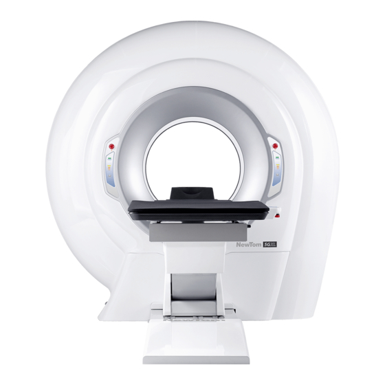
It is also possible to add more workstations for data processing and storage. For additional informational about this matter, please refer to the "NNT User Manual". Figure 2: NewTom 5G Vet complete system NOTE: The system may not be expanded with parts or accessories... -
Page 17: Scanning Unit
4 Getting started 4.4 Scanning unit 4.4.1 Signalling and command keyboards The scanning unit, called Scanner, is the centre of the system. At the sides of the scanning hole, on the circular ring shaped cover, there are two keyboards for the lights that indicate the device is switched on and the status of x-ray emissions. -
Page 18: Main Switch And Input Panel
4 Getting started 4.4.2 Main switch and input panel Please refer to the paragraph of the same name in the “User Manual”. 4.5 Patient table with stretcher The patient table with stretcher is the system accessory used for the positioning of the animal. Located on a special arm is the control button for moving the table;... -
Page 19: Patient Table With Stretcher Console
4 Getting started 4.5.1 Patient table with stretcher console Figure 3: Patient table with stretcher console Button Function Warnings UP/DOWN Raise and lower the table These movements are not allowed in case of "facilitated uphill position". The minimum / maximum excursions of the movements are limited to defaults values by active collision controls. - Page 20 4 Getting started Start sequence Operation allowed when the display show a “Facilitated Uphill Position” window with P2 symbol (ie if the stretcher is completely out of the gantry with active limit switch). + / - The function depends on the current page + / - buttons displayed on the screen LASER...
-
Page 21: Standard Accessories
4 Getting started 4.6 Standard accessories Please refer to the paragraph of the same name in the “User Manual”. 4.7 Cables Please refer to the paragraph of the same name in the “User Manual”. 4.7.1 Optional accessories Please refer to the paragraph of the same name in the “User Manual”. 4.8 System accessories Please refer to the paragraph of the same name in the “User Manual”. -
Page 22: Preliminary Procedures
5 Preliminary procedures Preliminary procedures Please refer to the paragraph of the same name in the “User Manual”. 5.1 Daily Check Please refer to the paragraph of the same name in the “User Manual”. 5.2 Blank Acquisition Please refer to the paragraph of the same name in the “User Manual”. 5.2.1 Invalidating the Blank acquisition Please refer to the paragraph of the same name in the “User Manual”. -
Page 23: Scanning
6 Scanning Scanning Please refer to the paragraph of the same name in the “User Manual”. 6.1 Animal scan 6.1.1 Animal preparation An important step in a scan routine is well preparing the animal. This can contribute to a proper scanning and to high quality images. - Page 24 6 Scanning NOTE: Pay attention to don't load excessively the parts of the patient table. The allowed maximum loads are: The patient table can support animals with a maximum weight of 160 Kg (plus 15kg of possible accessories). Below are details of the allowed maximum load distribution: Patient Table with stretcher: 1) Maximum load (for zone) Stretcher out of the gantry...
- Page 25 6 Scanning 1) After the device has been turned ON, the patient's table position should be reset (facilitated uphill position). Make sure that the stretcher is completely out of the gantry and locked by the handle positioned at the side of the table console. Then, press P2 button on the table console.
- Page 26 6 Scanning Figure 6: Patient table in exam preparation position 3) Unlock the stretcher and slide it into the gantry. Then relock the stretcher. Figure 7: Patient table with stretcher into the gantry Veterinary Application...
- Page 27 6 Scanning 4) Assure the animal will keep a correct posture Figure 8: Examples of positioning 5) Finely adjust the animal position by using the table console buttons.(UP/DOWN – LEFT/RIGHT). In order to help the operator during the positioning of the patient, the laser can be turned on by pressing the LASER button on the scanner control panels or on the table console (required the NNT software to be open).
- Page 28 6 Scanning Press P2 button in order to reset the animal table to the default position (facilitated uphill position) and allow the patient to leave the room. Veterinary Application...
-
Page 29: Quality Assurance
7 Quality assurance Quality assurance Please refer to the paragraph of the same name in the “User Manual”. 7.1 Phantom positioning Please refer to the paragraph of the same name in the “User Manual”. 7.2 Images samples Please refer to the paragraph of the same name in the “User Manual”. 7.3 Storage of QA data Please refer to the paragraph of the same name in the “User Manual”. -
Page 30: Troubleshooting
8 Troubleshooting Troubleshooting Please refer to the paragraph of the same name in the “User Manual”. Veterinary Application... -
Page 31: Iec61223: Acceptance Test
9 IEC61223: Acceptance Test IEC61223: Acceptance Test Please refer to the paragraph of the same name in the “User Manual”. Veterinary Application... -
Page 32: Appendix A- Technical References
10 APPENDIX A- Technical references 10 APPENDIX A- Technical references Scanner Scanning system Single rotation and volumetric acquisition. (cone beam technology) Scan parameters Scan time / X-ray emission time 18-36 s / 2.4-7.3 s Sampling angle 360° Patient's centering Fixed position Positioning lasers Anatomical analyzed volume Cylinder... - Page 33 10 APPENDIX A- Technical references Detector Pixels 1920 x 1536 Pixels Pixel size 127 x 127 m Pixel depth Frame rate Max Scout view radiological images [18x16] Image pixels 768 x 960 Pixels Pixel depth Pixel Size 0.254 x 0.254 [15x22e] Image pixels 2 x (672 x 768)
- Page 34 10 APPENDIX A- Technical references [12x8] HiRes Image pixels 1140 x 1000 Pixels Pixel depth Pixel Size 0.127 x 0.127 [8x8] HiRes Image pixels 906 x 988 Pixels Pixel depth Pixel Size 0.127 x 0.127 [6x6] HiRes Image pixels 728 x 744 Pixels Pixel depth Pixel Size...
- Page 35 10 APPENDIX A- Technical references [12x8] Shape Cylinder Reconstructed Volume Size Ø12 x H8 Voxel Size 0.300 0.250 0.200 0.150 Image pixels 410 x 410 492 x 492 614 x 614 820 x 820 Pixels Pixel depth [8x8] Shape Cylinder Reconstructed Volume Size Ø8 x H8 Voxel Size...
- Page 36 10 APPENDIX A- Technical references [6x6] HiRes Shape Cylinder Reconstructed Volume Size Ø6 x H6 Voxel Size 0.150 0.125 0.100 0.075 Image pixels 410 x 410 492 x 492 614 x 614 672 x 672 Pixels Pixel depth 10-6 Veterinary Application...
- Page 37 10 APPENDIX A- Technical references Radiological parameters X-Ray Tube IAE model X22 0.3/0.6 Veterinary Application 10-7...
- Page 38 10 APPENDIX A- Technical references 10-8 Veterinary Application...
- Page 39 10 APPENDIX A- Technical references Veterinary Application 10-9...
- Page 40 10 APPENDIX A- Technical references 10-10 Veterinary Application...
- Page 41 10 APPENDIX A- Technical references Veterinary Application 10-11...
- Page 42 10 APPENDIX A- Technical references X-Ray tube head Manufacturer IMD s.r.l. Model HF1R X-ray tube IAE X22 0.3/0.6 Classification (IEC 601-1) Class I Type B PHYSICAL DATA Material X-ray tube housing Aluminum Thermal capacity 550 kJ Maximum continuos thermal dissipation 60 W @ 110kV, 3.6 mA, 10 ms, 15 FPS Temperature maximum 60...
- Page 43 10 APPENDIX A- Technical references Cooling curve Rotor HF1R Startup 230Vac / 0.8s / 10A Running 60Vac / 2A X-Ray source assembly Model HF1R X-ray tube IAE X22 0.3/0.6 Focus - detector distance 970 mm Focus - skin distance minimum 150 mm Total filtration 4.4 mm Al @ 70 kV...
- Page 44 10 APPENDIX A- Technical references Inverter IMD S.r.l. Manufacturer HF1 3.5kW / HF1 3.5kW PLUS Model INPUTS 3.5 kW Maximum power 230 V ( 10%) Supply voltage Sinusoidal 50/60 Hz Waveform 16 A Maximum current 0.14 ohm Apparent supply resistance OUTPUTS 350 Vpk Peak voltage...
- Page 45 10 APPENDIX A- Technical references Dose declaration CTDI table declared for operative modalities of the device Values are expressed in mGy. Tolerance is 30%. Values measured according to IEC 60601-2-44: 2009 Par 203.109.1 Eco Scan Regular Scan Regular Scan Enhanced Scan Enhanced Scan Standard Dose...
- Page 46 10 APPENDIX A- Technical references CTDI 14,0 20,9 28,6 100 (90°) CTDI 12,0 18,0 24,5 100 (180°) CTDI 13,2 19,5 26,9 100 (270°) CTDI 13,4 20,4 27,4 100 (periph.) CTDI 10,1 15,1 20,5 100 (centre) CTDI 11,6 17,4 23,5 100 (0°) CTDI 10,3 15,7...
- Page 47 10 APPENDIX A- Technical references CTDI table declared for operative modalities of the device Values expressed in mGy. Tolerance is 30%. The values correspond to CTDIw CTDIvol for this application Values calculated according to IEC 60601-2-44: 2009 Par 201.3.211 and 201.3.212 c) Eco Scan Regular Scan Regular Scan...
- Page 48 10 APPENDIX A- Technical references CTDIvol table Values expressed in mGy. Tolerance is 30%. Values calculated according to IEC 60601-2-44: 2009 Par 201.3.211 and 201.3.212 c) Eco Scan Regular Scan Regular Scan Enhanced Scan Enhanced Scan Standard Dose Standard Dose Boosted Dose Standard Dose Boosted Dose...
- Page 49 10 APPENDIX A- Technical references DLP table declared for operative modalities of the device cm. Tolerance is 30%. Values calculated according to IEC 60601-2-44: 2009 Par 201.3.214 c) Values expressed in mGy Eco Scan Regular Scan Regular Scan Enhanced Scan Enhanced Scan Standard Dose Standard Dose...
- Page 50 10 APPENDIX A- Technical references CTDI table declared for operative modalities of the device free air Values expressed in mGy. Tolerance is 30%. Values calculated according to IEC 60601-2-44: 2009 Par 203.109.2 Eco Scan Regular Scan Regular Scan Enhanced Scan Enhanced Scan Standard Dose Standard Dose...
- Page 51 10 APPENDIX A- Technical references Indication of the dose profiles Graphs calculated according to IEC 60601-2-44: 2009 Par. 203.110 Regular scan, Standard dose, 1.96mAs 3.6s Regular scan, Standard dose, 1.96mAs 3.6s Veterinary Application 10-21...
- Page 52 10 APPENDIX A- Technical references Regular scan, Standard dose, 2.94mAs 5.4s Date: 2012-06-20 10-22 Veterinary Application...
- Page 53 10 APPENDIX A- Technical references Stray radiation diagram Stray radiation (uGy/mAs) according to IEC 60601-2-44: 2009 Par. 203.13 Measured by using “head phantom" according to IEC 60601-2-44: 2009 Par 203.108 Veterinary Application 10-23...
- Page 54 10 APPENDIX A- Technical references Laser Output power 0.9 mW Wavelenght 635 nm Beam divergence 70º Pulse lenght Onda continua Classification Classe 1 Other data 220 V ~ (± 10%) / 230 V ~ (± 10%) / 240 V ~ (± 10%) Absorbed power: 50/60 Hz (±...
- Page 55 TABLE: Guidance and manufacturer's declaration - electromagnetic emissions The device NewTom 5G Vet is intended for use in the electromagnetic environment specified below. The customer or the user of the device NewTom 5G Vet should assure that is used in such an environment. Emission test...
- Page 56 TABLE: Guidance and manufacturer's declaration - electromagnetic immunity The device NewTom 5G Vet is intended for use in the electromagnetic environment specified below. The customer or the user of the device NewTom 5G Vet should assure that is used in such an environment. Immunity test...
- Page 57 RF transmitters, an electromagnetic site survey should be performed. If the measured field strength in the location in which the NewTom 5G Vet is used exceeds the RF compliance level above, the NewTom 5G Vet should be observed to verify normal operation.
- Page 58 TABLE: Recommended separation distances between portable and mobile RF communications equipment and the equipment The device NewTom 5G Vet is intended for use in the electromagnetic environment in which radiated RF disturbances are controlled. The customer or the user of the device NewTom 5G Vet can help prevent...
- Page 59 10 APPENDIX A- Technical references All components, accessories, spare parts must be approved and supplied by CEFLA s.c. Particularly, the connection cables must be ONLY the ones described under Par. 4.7 - “Cables“. WARNING: Use of accessories, transducers, and cables other than those...
-
Page 60: Appendix B - Security Standards
11 APPENDIX B – Security standards 11 APPENDIX B – Security standards The NewTom 5G Vet equipment has been built in conformity with IEC normative regarding safety of electric- medical devices of similar typology and, particularly, with the normative: IEC 60601-1: 2005 + CORR. 1 (2006) + CORR. 2 (2007) - General requirements for basic safety and •... -
Page 61: Appendix C - Labels
12 APPENDIX C - Labels 12 APPENDIX C - Labels PLATE ON SCANNER ✔ Position: Rear plastic cover on the bottom left side Veterinary Application 12-1... - Page 62 12 APPENDIX C - Labels X-RAY WARNING LABEL ✔ Position: Front plastic cover on the bottom left side. 12-2 Veterinary Application...
- Page 63 12 APPENDIX C - Labels MAIN SWITCH AND INPUT FUSE LABEL ✔ Position: Rear plastic cover on the bottom left side, next to the main switch. WARNING LABEL FOR DEVICES WITH LASER (NORMAL USE) ✔ Position: Rear plastic cover on the bottom left side on top of the scanner label. Veterinary Application 12-3...
- Page 64 WARNING LABEL FOR LASER DEVICES (DISTANCE <40MM) ✔ Position: On the laser brackets next to the laser modules (1 for each laser). ETICHETTA GLOBALE BEAM LIMITER ✔ CEFLA s.c. – Italy P/N 96600716 P/N 99934389 S/N ___________ Position: On “LAMIERA FISSA PIOMBO FP 5G” of collimator...
- Page 65 12 APPENDIX C - Labels BEAM LIMITER EQUIVALENT FILTER LABEL ✔ CEFLA s.c. – Italy Al - P/N 99934483 2 mm Al @ 75 kV Position: On the 2mm aluminum filter of the beam limiter. BEAM LIMITER EQUIVALENT MIRROR PLATE LABEL ✔...
- Page 66 12 APPENDIX C - Labels RJ45 ETHERNET CONNECTOR LABEL ✔ ETHERNET Position: Rear plastic cover on the bottom left side, next to the Ethernet connector. HAND CRUSHING WARNING LABEL ✔ Position: On the main structure, next to the points with risk of hand crushing. FOLLOW INSTRUCTIONS FOR USE LABEL ✔...
- Page 67 12 APPENDIX C - Labels X-RAY SOURCE LABEL ✔ Position: On the X-ray source tube head. INVERTER LABEL ✔ Position: On the inverter chassis. USA FEDERAL LAW LABEL ✔ CAUTION: Federal law restricts this device to sale by or on the order of a practitioner licensed by the law of the State in which he practices to use or order the use of x-ray imaging systems.
- Page 68 NEWTOM™ 5G is a commercial trademark of CEFLA s.c. All other products and brand names are registered trademarks or trademarks of their respective companies. NEWTOM™ 5G is manufactured by: CEFLA s.c. Phone: +39 045 8202727 Fax +39 045 8203040 e-mail: info@newtom.it...
Need help?
Do you have a question about the NewTom 5G Vet and is the answer not in the manual?
Questions and answers