Table of Contents
Advertisement
Advertisement
Table of Contents

Related Manuals for CEFLA NewTom VGi evo


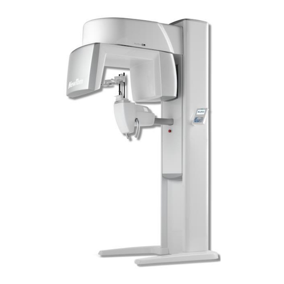
Summary of Contents for CEFLA NewTom VGi evo
- Page 1 97070043 Rev. 5 04.05.2018...
- Page 2 This document is provided as a consultation manual intended for the device users. CEFLA s.c. follows a policy based on the constant development and update of the product. For this reason, it reserves the right to change the content of this manual without prior notice.
-
Page 3: Table Of Contents
SUMMARY TARGET AND APPLICATION FIELD ........................1-1 UNPACKING AND MOVING THE EQUIPMENT....................2-1 2.1 I ......................2-1 NSPECTION AND UNPACKING INSTRUCTIONS 2.1.1 Opening crate 1 ..........................2-2 2.1.2 Opening crate 2 ..........................2-3 2.1.3 Opening crate 3 ..........................2-3 MOUNTING THE EQUIPMENT ........................3-1 3.1 L .............................. -
Page 4: Target And Application Field
For more details about “NewTom VGi evo”, please refer to the “Service Manual” document. This manual is intended for trained personnel recognized by the manufacturer of the “NewTom VGi evo” device. Prior to operating or servicing this device, this manual must be read and understood. -
Page 5: Unpacking And Moving The Equipment
Do not attempt set-up, installation, or operation of any damaged system. WARNING: Never try to uncrate and stand up the equipment before unloading from the delivery truck. NewTom VGi evo – Installation Manual rev 5... -
Page 6: Opening Crate 1
2.1.1.2 Cartoon box 2 The second box includes the parts listed below 99935030 99934961 99934962 99934963 2.1.1.3 Cartoon boxes 3-4 The third and fourth boxes includes the parts listed below 99935013 99935014 99935015 99935016 NewTom VGi evo – Installation Manual rev 5... -
Page 7: Opening Crate 2
Carefully open the crate and loosing the wooden screw, remove the top and lateral sides of the crate. Slide the rotating arm out of the base together with its wood support. Rebuild the crate as it will be use to support the rotating arm during its assembly on the column. NewTom VGi evo – Installation Manual rev 5... -
Page 8: Mounting The Equipment
FLAT WASHER SPLIT LOCK NOTE: To conduct installation and maintenance, the NewTom VGi evo requires a minimum distance of 25 cm (10 inches) from the rear wall and 25 cm (10 inches) from the sidewalls. Define the final position of the machine. - Page 9 Install the feet of the device on the two legs. Mount the two legs of the device using the provided bolts. NewTom VGi evo – Installation Manual rev 5...
- Page 10 Wires and terminal numbering must coincide! Connect to the XM3 terminal bar the wires from the control box(1) . Connect the earth cable from the control box to the earth bar (2). NewTom VGi evo – Installation Manual rev 5...
- Page 11 (4 screws on each side). Remove the crate and carefully slide out the wood structure. Once they are accessible, tighten the two last M6x30 screws on the structure. NewTom VGi evo – Installation Manual rev 5...
- Page 12 Wires numbering must coincide! Properly connect the wires to M3 terminal (2). WARNING: Wires and terminal numbering must coincide! Fasten the earth cable (3). Remove the locking plate from the rotating arm. NewTom VGi evo – Installation Manual rev 5...
-
Page 13: Connecting The Equipment
(detachable) power cord with plug and socket, since this might invalidate the conditions upon which certain technical certifications (CE, CSA, …) are based. “NewTom VGi evo” is delivered with a 10m long power cable already assembled (for the Chinese Market please see the note below). - Page 14 “NewTom VGi evo” can operate at any of the following nominal mains voltages: 100 / 115 / 200 / 220 / 230 / 240 Vac. The equipment can operate (with the rated specification) with a +/-10% tolerance range respect to the nominal mains voltage.
- Page 15 (effective current) aforementioned. “NewTom VGi evo” is delivered from the factory with mains line fuse F1 (see picture) set for 230V, i.e. T10A. In case of mains power in the 100-115V range, replace fuse F1 with a T15A fuse. Spare fuses are originally delivered with “NewTom VGi evo”.
-
Page 16: Connecting The External Emergency Button
The XM1 terminal block provides the connection to the internal switch: the two wires of the cable must be connected with terminal Once the cable is connected fix it to the control box with the cable NewTom VGi evo – Installation Manual rev 5... -
Page 17: Connecting The External Door Switch (Optional)
4 wires RJ11 cable cable with a six wire RJ11. It is recommended to do not exceed a length of 20 mt. Extension RJ11 cable X-ray button Function BROWN X-ray emission switch BROWN X-ray emission switch WHITE WHITE “Ready” LED BLUE “Emission” LED n.c. n.c. n.c. n.c. n.c. NewTom VGi evo – Installation Manual rev 5... -
Page 18: Connecting The Console Workstation
(especially behind the computer). Shelter the cables by using surface raceways or cable protectors, and place them away from walk areas in order to avoid people to trip over them. NewTom VGi evo – Installation Manual rev 5... -
Page 19: Mounting The Equipment Covers
1. Temporarely connect the emergency button on connector C40. 2. Manually move the rotating arm at the reset position by pressing the PB3 button on the NIM040A located at the RP1 rack (see below). NewTom VGi evo – Installation Manual rev 5... - Page 20 3. Mount the "CARTER COP.INF.CARRO TRAS.NEXT - 99934969" on the "CARTER TRASLANTE - 99935017 " with n°4 M5x16 TCCE screws. 4. Fix the "CARTER TRASLANTE - 99935017" with n°6 M6x20 TBCE (3 screws on each side). After that centering the laser like last paragraph. NewTom VGi evo – Installation Manual rev 5...
- Page 21 These cables do not have to be connected. 7. Place the cable of the two laser as shown in the following pictures, fixing in with the aid of cable ties, then insert the C18 connector in the connector plate. NewTom VGi evo – Installation Manual rev 5...
- Page 22 8. Fix the “LAMIERA INF CHIUSURA MENSOLA - 99935023” with n°2 M6x10 TCCE and n°2 M5x10 TSCE. 9. Place the " LAMIERA CHIUSURA SUP TRAV ROT - 99935030" and fix it with n°4 M5x10 TSCE. NewTom VGi evo – Installation Manual rev 5...
- Page 23 Rotate the arm until you can see the holes for the screws. Fix the cover with n°4 M5x10 TSCE. 11. Place the " CARTER SELLA BR. ROTANTE NEXT - 99934963". Fix the cover with n°4 M5x10 TSCE screws. NewTom VGi evo – Installation Manual rev 5...
- Page 24 13. Mount the “GR RULLO VGI EVO - 96603008”. Gently tighten the nuts located at the extremities of the roller, paying attention to do not lock the roller. 14. Insert the “Counterweight” inside the two green rail by sliding it from the bottom. NewTom VGi evo – Installation Manual rev 5...
- Page 25 Please verify if the console you received is supposed to be mounted on the right (default) or on the left. Next steps refer to a console mounted on the left side of the scanner. NewTom VGi evo – Installation Manual rev 5...
- Page 26 18. Mount the four iron spacers on the back of the main structure as shown in the following picture. 19. Mount the “VASCA INFERIORE - 99934748” 20. Mount the “ATTACCO GRUPPO CONSOLE SX – 99935028” on the “MONTANTE SX SUPERIORE – 99935013” using n°4 M4 nuts with split lock washer. NewTom VGi evo – Installation Manual rev 5...
- Page 27 22. Place the two covers previously coupled, on the scanner unit, then fix them with n°3 M6x8 TBCE and with n°3 M6x50 TBCE (see following pictures). Carefully pass the cables for the console inside the holes of the cover. NewTom VGi evo – Installation Manual rev 5...
- Page 28 24. Pass the cable in the console pipe, connect the cable extensions and close the pipe using the provided cap. 25. Connect the two cables to connectors KCB1 and KAL5 and of the console board, then close the console as shown in the following pictures using the provided screws. NewTom VGi evo – Installation Manual rev 5 5-10...
- Page 29 M6x20 TCCE with washer and nuts. 27. Place the two covers previously coupled, on the scanner unit, then fix them with n°3 M6x8 TBCE and with n°3 M6x50 TBCE (see following pictures). NewTom VGi evo – Installation Manual rev 5 5-11...
- Page 30 30. Screw n°2 6x20 TBCE on the top of the scanner as show in the following pictures. Be sure to do not tighten the bolts all the way as they will be used as guides for the next cover. NewTom VGi evo – Installation Manual rev 5...
- Page 31 33. Raise the rotating arm to reach the maximum height. 34. Mount the “GR POGGIAMENTO MOT. VGI EVO - 96603001” using n°4 M6x70 TCCE with washers. Bolts can be tightened by accessing them from the back of the column. NewTom VGi evo – Installation Manual rev 5 5-13...
- Page 32 36. Mound the two handle bars as shown in the following picture 37. Be sure the Ethernet cable is properly connected to the RJ45 adapter as shown in the following picture. NewTom VGi evo – Installation Manual rev 5 5-14...
- Page 33 40. Mount the “PANNELLO INFERIORE POST – 99935019” and fix it with n°4 M6x8 TBCE screws. NOTE: the last rear cover, the “PANNELLO CENTRALE POST- 99935020” will be mounted after the laser position has been verified. NewTom VGi evo – Installation Manual rev 5 5-15...
- Page 34 M5x10 TSCE screws. 43. Mount the " CARTER GENERATORE NEXT- 99934961" and fix it with n°2 M5x10 TSCE screws (upper side). Pay attention for the joints (lower side). NewTom VGi evo – Installation Manual rev 5 5-16...
- Page 35 45. Mount the " CARTER PIEDE DX COMPLETO - 99935045" and the “CARTER PIEDE DX COMPLETO - 99935046”. 46. Mount the “GR TAVOLETTA - 96603021” on the motorized head support in order to be ready for the calibration of the device. NewTom VGi evo – Installation Manual rev 5 5-17...
-
Page 36: Fixing The Device
In case of installation in a environment subject to significant vibrations, the bolts could be fit with rubber vibration- dumping pads. Rubber bumpers can also be used underneath the legs. NewTom VGi evo – Installation Manual rev 5 5-18... - Page 37 NewTom VGi evo – Installation Manual rev 5 5-19...
- Page 38 In case of installation in a environment subject to significant vibrations, the bolts could be fit with rubber vibration- dumping pads. Rubber bumpers can also be used underneath the legs. NewTom VGi evo – Installation Manual rev 5 5-20...
-
Page 39: Testing The Equipment
6 Testing the equipment 6.1 Electrical safety checks Please contact the CEFLA S.C. Technical Support for more informations about tests. WARNING: The electrical safety checks involve the use of dangerous tensions. It is necessary pay the maximum attention, before, during and after the... -
Page 40: Calibrating The System
□ Wait 10 minutes. □ Perform the X-Ray source conditioning process (Scanner Test → Tools → X-Ray source conditioning). NewTom VGi evo – Installation Manual rev 5... - Page 41 12. Verify the laser alignment (refer to the corresponding VGi evo Service Manual). □ 13. Perform the “Head Rest Calibration” scanning a QA Phantom 8x8 HiRes (refer to the corresponding VGi evo Service Manual). NewTom VGi evo – Installation Manual rev 5...
-
Page 42: Finishing Touches
QA report and store with the other registrations of the device. ONLY FOR USA: Upon completion of an installation, please fill out and review the manufacturer’s “Installation checklist” (code 97050874) that can be found on the Disk documentation. NewTom VGi evo – Installation Manual rev 5... - Page 43 NEWTOM™ is a commercial trademark of CEFLA s.c. All other products and brand names are registered trademarks or trademarks of their respective companies. NEWTOM™ VG series is manufactured by: CEFLA s.c. Phone: +39 045 8202727 Fax +39 045 8203040 e-mail: info@newtom.it...
Need help?
Do you have a question about the NewTom VGi evo and is the answer not in the manual?
Questions and answers