Table of Contents
Advertisement
Advertisement
Table of Contents

Subscribe to Our Youtube Channel
Related Manuals for CEFLA NEWTOM 5GXL


Summary of Contents for CEFLA NEWTOM 5GXL
- Page 1 97050723 Rev. 4 05.02.2018...
- Page 2 This document is provided as a consultation manual intended for the device technicians. CEFLA s.c. follows a policy based on the constant development and update of the product. For this reason, it reserves the right to change the content of this manual without prior notice.
-
Page 3: Table Of Contents
SUMMARY Sommario About this manual ..........................1-1 1.1 Contents ............................... 1-1 1.2 Structure ..............................1-1 1.3 Attached documents ........................... 1-2 1.4 Conventions used in this manual ......................1-2 1.5 Typhography ............................... 1-2 Safety information ..........................2-1 2.1 General safety ............................. 2-1 2.2 Electrical safety ............................ - Page 4 9.16.2 Centering the laser ..........................9-23 9.17 Daily Check .............................. 9-25 Electronic components diagram ....................10-1 10.1 Inverter ..............................10-2 10.2 Monoblock ............................... 10-3 Troubleshooting ..........................11-1 11.1 NNT Log error viewer (only from NNT 8.0) ................... 11-1 11.2 Motor test ..............................11-1 11.3 Phantom analysis ............................
-
Page 5: About This Manual
Chapter 11 – provides guidelines to solve problem or failure that could happen. Chapter 12 – “Extranet site” describes how to access to the documentation included in the extranet site http://extranetmedical.cefla.it. NewTom 5G XL – Service Manual rev 4 Pag. 1-1... -
Page 6: Attached Documents
About this manual ______________________________________________________________________________________ 1.3 Attached documents The following documents are attachments of this manual: “5G XL - Installation Manual” Cod. 97070044 “Workstation Setup annex” Cod. 97050818 1.4 Conventions used in this manual The general safety information in this part of the manual is for servicing personnel. Specific warning and cautions will be found throughout the manual where they apply. -
Page 7: Safety Information
Safety information ______________________________________________________________________________________ 2 Safety information The following section contains the safety information that you need to be familiar with before servicing a “NewTom 5G XL”. Additional information are included inside the “User Manual”. 2.1 General safety Follow these rules to ensure general safety: ... -
Page 8: Electrical Safety
WARNING: The “Newtom 5G XL” is an equipment, containing high voltage devices and must be opened only by qualified personnel, authorized by CEFLA s.c. WARNING: Use only approved tools and test equipment. Some hand tools have handles covered with a soft material that does not insulate you when working with live electrical currents. - Page 9 Safety information ______________________________________________________________________________________ Before you start working on the machine, unplug the power cord. If you cannot unplug it, ask the customer to power-off the wall box that supplies power to the machine and to lock the wall box in the off position. ...
-
Page 10: Input Power Connection
Safety information ______________________________________________________________________________________ iii.All the electronic boards If an electrical accident occurs: iv.Use Caution: do not become a victim yourself. v.Switch Off power. vi.Send another person to get medical aid. Never connect to the system any other parts or accessories not specified from the manufacturer. ... -
Page 11: Handling Electrostatic Discharge-Sensitive Devices
Safety information ______________________________________________________________________________________ Check for any obvious alterations. Use good judgment as to the safety of any alterations. Check inside the unit for any obvious unsafe conditions, such as metal filings, contamination, water or other liquids, or signs of fire or smoke damage. Check for worn, frayed, or pinched cables. -
Page 12: X-Ray Warnings
Safety information ______________________________________________________________________________________ 2.7 X-Ray warnings This equipment is a radiological device that can expose the personnel to the risk resulting from ionizing radiation. It must be used in compliance with safety regulations, required by current radioprotection regulations in accordance with local laws. -
Page 13: General Information
General information ______________________________________________________________________________________ 3 General information 3.1 Symbols on the package The following table illustrates the symbols used for the shipment of the equipment: Symbol Meaning FRAGILE THIS WAY UP KEEP AWAY FROM RAIN DO NOT STACK TEMPERATURE LIMITS NewTom 5G XL – Service Manual rev 4 Pag. -
Page 14: Symbols On The Labels
General information ______________________________________________________________________________________ 3.2 Symbols on the labels Next table provides a description of the symbols included on the device’s labels. Symbol Standard Description IEC 60417-5010 ON / OFF (push-push) IEC 60417-5032 Alternating current ISO 7000-0434A Caution ISO 7010-W001 General warning sign IEC 60878 Warning: dangerous voltage ISO 3864-B.3.6... -
Page 15: Enabling The Service Level
General information ______________________________________________________________________________________ EN 980:2008 Date of manufacture EN 980:2008 Manufacturer ISO 7000-1641 Operating instructions ISO 7010-M002 Refer to instruction manual/booklet 3.3 Enabling the Service level In order to enable the service level, first left click on the NNT main window and then press CTRL + ALT + SHIFT + END on the keyboard: The service level is automatically disabled, every time the software is closed. -
Page 16: Arm Motor Consolle
General information ______________________________________________________________________________________ 3.6 Arm motor consolle On the top left side of the service window, the motor console is located. This console can be used to move and monitor the status of the rotating arm. Next is a brief explanation of the console commands. FC+ led Display the status of the forward limit switch. -
Page 17: System Overview
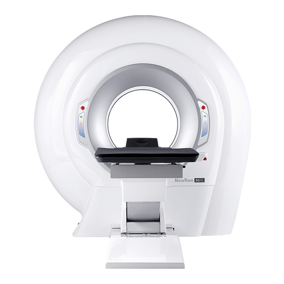
System overview ______________________________________________________________________________________ 4 System overview The NewTom 5G XL is a cone beam computed tomography x-ray system. The device is intended for diagnostic use obtaining geometric information and radiologic density from two-dimensional and three-dimensional images of objects in the examined area. Through a scan process the system acquires the data which, after have been stored inside a computer, are used by the software to reconstruct the volume of the patient’s anatomical parts. -
Page 18: Installing The System
Installing the system ______________________________________________________________________________________ 5 Installing the system For a detailed description of the installation procedure, refer to the attached document “Installation Manual” code 97070044. NewTom 5G XL – Service Manual rev 4 Pag. 5-1... -
Page 19: Console Preparation
Console preparation ______________________________________________________________________________________ 6 Console preparation The console workstation (or main workstation) is the computer that controls the scan machine. Specific requirements, procedures and settings must be followed in order to prepare the computer to run the machine and to obtain extreme performance. The computer must comply with the specifications described in the “Workstation Setup”... -
Page 20: Networking And Archive
Networking and archive ______________________________________________________________________________________ 7 Networking and archive The NNT software has been designed to provide the best functionality and performance when it is installed in a LAN (Local Area Network) or workgroup. Working in a workgroup means that different workstations have to share the same archives. In the case of “NewTom VGi evo”... -
Page 21: Calibrating The System
Calibrating the system ______________________________________________________________________________________ 8 Calibrating the system In order to perform the calibration, the “Service level” must be enable the Service level (see “3.3 Enabling the Service level”). 8.1 TIN Calibration The TIN is a tool to perform the calibration. In order to calibrate the device, see the following steps: Select Scan →... - Page 22 Calibrating the system ______________________________________________________________________________________ The software will acquire an image of the TIN. The goal is to have the two spheres located on the right part of the TIN, included in the two red boxes drawn on the right side of the image, and the four spheres located in the center of the TIN, included in the two red boxes drawn in the center of the image (see...
-
Page 23: Verifying The Calibration
Calibrating the system ______________________________________________________________________________________ 8.2 Verifying the calibration In order to verify that the 3D calibration is correct, it is highly recommended to perform two scans on the QA phantom, one using the 21x19 FOV and one using the 8x8 HR FOV. 1) Remove the head support and move the table to the “exam preparation position”... - Page 24 Calibrating the system ______________________________________________________________________________________ The brighter dots (representing the holes of the aluminum pipe of the phantom) are crossed by the two horizontal dashed lines as showed in the following picture (red circles). The phantom is aligned with the vertical dashed line as showed in the following picture (green circle) 10) In order to adjust the position of the phantom...
- Page 25 Calibrating the system ______________________________________________________________________________________ 13) Wait until the scan has been completed. When prompted by the software (see following picture) select “Yes”. 14) The analysis of the phantom scan will be performed, showing a table with the resulting values. In case a value is out of range, three asterisks will appear on its side.
-
Page 26: Calibration Backup
Installer of the current version of the NNT software at the moment the unit was manufactured User manuals Technical manuals (in a zipped file with password "Cefla", for field engineer use only) NewTom 5G XL – Service Manual rev 4... -
Page 27: Maintenance Of The System
Maintenance of the system ______________________________________________________________________________________ 9 Maintenance of the system This chapter provides a list of procedures to test and eventually replace different components of the system. WARNING: Always switch the system off before any maintenance of the device! NOTE: The equipment doesn’t include parts inclined to deterioration. -
Page 28: Replacing The Computer
Maintenance of the system ______________________________________________________________________________________ 9.2 Replacing the computer This chapter provides the guidelines for the replacement of the computer directly connected to the scanner (Main WS). 1) Settings backup In case the original workstation is still accessible, perform the following backups:: ... -
Page 29: How To Remove The Covers Of The Machine
Maintenance of the system ______________________________________________________________________________________ 9.3 How to remove the covers of the machine Removing “Front Panel Thermoformed Carter” (97465033) Remove the M4x20 hex. socket screw on the left side of the Front Panel Thermoformed Carter (see following image) Lower the Front Panel Thermoformed Carter (1) in order to unhook it from the top, therefore pull the panel (2) to unhook it from the right side. - Page 30 Maintenance of the system ______________________________________________________________________________________ Removing the posterior “Plastic Ring” (97465075) Remove the self-tapping screw on the plastic ring and then gently pull the plastic ring completely out Removing the “Anterior Thermoformed Carter” (97465031) Remove the 8 bolts that hold the carter and then gently pull the carter completely out Removing the “Posterior Thermoformed Carter”...
- Page 31 Maintenance of the system ______________________________________________________________________________________ NewTom 5G XL – Service Manual rev 4 Pag. 9-5...
-
Page 32: Rotating Gantry
Maintenance of the system ______________________________________________________________________________________ 9.4 Rotating gantry From the main toolbar, select Tools -> Scanner Test. The scanner test window will appear. 9.4.1 Running a motor test The motor test consists in one or more complete rotations of the arm. The results of the test are the number of encoder steps and the elapsed time. -
Page 33: Testing The Limit Switches
Maintenance of the system ______________________________________________________________________________________ 9.4.2 Testing the limit switches Use the scanner test window (see picture below) to verify the functionality of the limit switches. Mechanical limit switches Backward limit switch 1) From the “Scanner Test” window select the “FC-“ button. 2) Select the “Move”... -
Page 34: Testing The Motor Controller Power Supply
Maintenance of the system ______________________________________________________________________________________ 9.5 Testing the motor controller power supply From the “Scanner Test ” window select Tools → Arm Motor Controller control. On the window that appears check that in the “Power Voltage” the value is around 40 Volts (30Vac rectified). 9.6 Testing the Patient Table connection 1) From the “Scanner Test ”... -
Page 35: Modifying The Flat Panel Ip Address
Maintenance of the system ______________________________________________________________________________________ Modifying the flat panel IP address The communication between flat panel and grabber card (Intel Gigabit CT Desktop adapter)is performed through the TCP-IP protocol. By default the IP address assigned to the flat panel is 192.168.1.1, while the one assigned to the grabber card is 192.168.1.2. -
Page 36: Replacing The X-Ray Source
Maintenance of the system ______________________________________________________________________________________ 9.9 Replacing the x-ray source 1. Remove the covers of the scanner (refer to chapter “9.3 How to remove the covers of the machine” 2. Dismount the old x-ray source and replace it with the new one 3. -
Page 37: Uncorrected Pixel Management
Maintenance of the system ______________________________________________________________________________________ 9.10 Uncorrected pixel management In case the software during the blank procedure, detects a high number of pixels that cannot be corrected, the following error message will appear at the end of the process. Typically, this could happen after the replacement of the x-ray source and could be caused by some shadows inside the acquired image due to an incorrect x-ray source or collimator adjustment (typically, shadows will be located on the edges of the image). - Page 38 Maintenance of the system ______________________________________________________________________________________ 2. In this specific sample the file is “C:\NNT\ThalesConfig\1533TT_DefectMapref_ConfMode4__Zoom0.fxd” but it could also be a different one. 3. From the main WS of the scanner enable the Service level, then select Tools -> Scanner Test. 4.
- Page 39 Maintenance of the system ______________________________________________________________________________________ 7. Once the uncorrected area has been identified, it necessary to verify if the cause is a shadow and in case get rid of it. 8. Open the Beam Limiter Test selecting Tools -> Beam limiter calibration. 9.
- Page 40 Maintenance of the system ______________________________________________________________________________________ 12. Once the image does not show any shadow, is it possible to repeat the blank acquisition. 13. Following is the same defect map file open after the new adjustment of the x-ray source. It is possible to see that the white area previously located on the right side of the image disappeared, meaning the blank was successfully performed.
-
Page 41: Replacing The Flat Panel Detector
Maintenance of the system ______________________________________________________________________________________ 9.11 Replacing the flat panel detector Remove the anterior “Plastic Ring” (97465075), “Plastic Cylinder” (97465076) and “Anterior Thermoformed Carter” (97465031) in order to get access to the flat panel and converter board (refer to chapter “9.3 How to remove the covers of the machine”) Disconnect all the cables from the old flat panel and remove it (unscrewing the 5 bolts circled in the picture below). -
Page 42: Kv Curve
Maintenance of the system ______________________________________________________________________________________ 9.12 kV curve Enable the service mode, then in the scanner test window (TOOLS→SCANNER TEST) select the Small Focal Spot (button “SFS” selected). Select Calibration → kV Setup. Highlight the first step of the table (DAC = 0). Select “APPLY”. - Page 43 Maintenance of the system ______________________________________________________________________________________ In the “mA Curve Setup” window verify that: kV=110 “Rotating anode” flag is checked Sampling delay (ms) = 50 Adjusting the MINIMUM mA (range 0.95± 0.05 mA) Select the first line of the table, click on the “Apply” button and then on the “Rx On”...
-
Page 44: Adjusting The Collimator
Maintenance of the system ______________________________________________________________________________________ and repeat the above procedure from steps from n°3 to n°15. NOTE: In case the mA curve are already existing, it is also possible after completing step 1 of the above procedure to run the “Automatic procedure” by selecting the corresponding button located on the bottom right corner of the window. - Page 45 Maintenance of the system ______________________________________________________________________________________ After modifying the inclination of the bracket by adjusting each set screw, fix the position by tighten the holding bolts (see picture below). 4 Horizontal adjustment. Rotating the bracket plate will result in moving the collimated area to the left and/or to the right.
- Page 46 Maintenance of the system ______________________________________________________________________________________ In order to do that select the “Enable manual tuning” flag on the Beam limiter dialog… …then act on the single collimator positions as shown below. Once done acquire a new image pressing the “Acquisition” button. 7.
- Page 47 Maintenance of the system ______________________________________________________________________________________ 9. Repeat step 6 to 8 for each single FOV using the table here below in order to choose the right x ray parameters n. IMG mA (dosed) Time (ms) Expected GL Position Standard 110° 10k –...
-
Page 48: Image By Image Check
Maintenance of the system ______________________________________________________________________________________ 9.15 Image by Image check The software integrates the possibility to acquire a stack of images and later check the images one by one. This can be particularly useful in case of investigation related to possible instability of the x-ray source emission and/or detector acquisition. -
Page 49: Laser Setup
Maintenance of the system ______________________________________________________________________________________ 9.16 Laser setup 9.16.1 Adjusting laser voltage Laser voltages can be measured and adjusted on NIM040-A board (Fw ver. 20.0) located on Rotate Board RP1 (SX). The voltage for the laser should be 3.3 Vdc. Voltage of top laser (LASER 1) can be measured between TP2 (GND) and TP9 (V Laser1) and can be adjusted using trimmer TRIM1. - Page 50 Maintenance of the system ______________________________________________________________________________________ 3) If the laser traces are not orthogonal with the sticker's references (1), loose the M3x20 screw from the block of the laser (2) and rotate the laser module until it matches with the orthogonality of the sticker (3). Once done tighten back the M3x20 screw.
-
Page 51: Daily Check
Maintenance of the system ______________________________________________________________________________________ 7) …then adjust the position 9.17 Daily Check Following the list of tests performed by Daily Check procedure: Test N. 1: Beam limiter test. Test N. 2: The Arm moves to 0 degrees (same as RESET button on Hardware Test window). Test N. -
Page 52: Electronic Components Diagram
Electronic components diagram ______________________________________________________________________________________ 10 Electronic components diagram NewTom 5G XL – Service Manual rev 3 10-1... -
Page 53: Inverter
Electronic components diagram ______________________________________________________________________________________ 10.1 Inverter NewTom 5G XL – Service Manual rev 3 10-2... - Page 54 Electronic components diagram ______________________________________________________________________________________ 10.2 Monoblock X-Ray tube head PSM26 Board COLOR – WIRE SECT. CONNECTOR FUNCTION Power Connector *Black (1) 4x2,5 mm (14 AWG) shielded Power 230V AC OUT A Chain Terminal *Black (2) 4x2,5 mm (14 AWG) shielded Power 230V AC OUT A Power Connector *Black (3) 4x2,5 mm...
-
Page 55: Troubleshooting
Troubleshooting ______________________________________________________________________________________ 11 Troubleshooting Please use the official “Troubleshooting report” form (below an preview of Page 1) to report any problem to the manufacturer. The complete form can be downloaded from the extranet site under the “Forms/Warranty” menu (see chapter “Extranet site”). NewTom 5G XL –... -
Page 56: Nnt Log Error Viewer (Only From Nnt 8.0)
Troubleshooting ______________________________________________________________________________________ 11.1 NNT Log error viewer (only from NNT 8.0) The NNT Log Viewer is an utility integrated in the NNT software, used to visualize error, messages, information that occurred in the usage of the scanner and/or NNT application. For a complete guide of this application please refer to the document “NNT Log Viewer Guide”. -
Page 57: Phantom Analysis
Troubleshooting ______________________________________________________________________________________ 11.3 Phantom analysis Phantom analysis results out of range (***) Parameter What to do… Verify the phantom acquisition during the first scout view. If inclined adjust the phantom position. Verify the phantom acquisition during the second scout view. If tilted level the table. ScanTime Change CM2 motor controller First, perform a Daily Check then a new QA Phantom scan and analysis... -
Page 58: Extranet Site
Additional information can be downloaded from the dedicated extranet site http://extranetmedical.cefla.it. Only registered user can access to the site. If a new account is required please contact service.radiology@cefla.it. The site is mainly divided between the main menu on the left side and the products area on the right site. - Page 59 Extranet site ______________________________________________________________________________________ Clicking on a single product the corresponding window will pop up, listing all the available resources linked to that specific equipment. NewTom 5G XL – Service Manual rev 3 12-2...
- Page 60 CEFLA s.c. NEWTOM™ is a commercial trademark of All other products and brand names are registered trademarks or trademarks of their respective companies. NEWTOM™ 5G series is manufactured by: CEFLA s.c. Phone: +39 045 8202727 Fax +39 045 8203040 e-mail: info@newtom.it...
Need help?
Do you have a question about the NEWTOM 5GXL and is the answer not in the manual?
Questions and answers