Table of Contents
Advertisement
Quick Links
Advertisement
Table of Contents

Related Manuals for CEFLA NewTom 5G


Summary of Contents for CEFLA NewTom 5G
- Page 1 0051 97050196 Rev. 5 28.04.2017...
- Page 2 This document is provided as a consultation manual intended for the device users. CEFLA s.c. follows a policy based on the constant development and update of the product. For this reason, it reserves the right to change the content of this manual without prior notice.
-
Page 3: Table Of Contents
2.6 Artifacts and repetition of a scan................2-6 2.7 Protection from ionizing radiation................2-7 2.8 Protection from laser exposure................2-9 2.9 Devices connected to the NewTom 5G console ............2-10 2.10 Maintenance time lag..................2-11 3 SAFETY AND MAINTENANCE OF THE DEVICE............3-1 3.1 Installation requirements..................3-1 3.2 Guidelines for safety................... - Page 4 4.2 Working principle....................4-3 4.3 Overall view...................... 4-4 4.3.1 Control panels.................... 4-5 4.3.2 Patient table console...................4-6 4.3.3 Patient table with stretcher console..............4-8 4.3.4 Input panel and main switch.................4-10 4.4 Standard accessories..................4-10 4.4.1 Cables....................4-11 4.4.2 Optional accessories...................4-11 4.5 System start-up....................4-12 4.6 System shut down....................
- Page 5 10.6 Inverter....................... 10-13 10.7 Dose declaration.................... 10-14 10.8 Stray radiation diagram..................10-22 10.9 Laser......................10-23 10.10 Other data....................10-23 10.11 Electromagnetic compatibility................10-24 10.11.1 Essential performance................10-28 11 APPENDIX B – SECURITY STANDARDS...............11-1 12 APPENDIX C - LABELS.................12-1...
-
Page 6: Introduction To This Manual
This manual was created as a mean to provide information and instructions about using a NewTom ™ 5G device. This manual comprises all versions of the series (NewTom 5G, NewTom 5G version FP), in the following generically called “NewTom 5G”. - Page 7 APPENDIX A- Technical references ✔ Provides the technical reference of the device. APPENDIX B – Security standards ✔ Lists the standards conformity of the device. APPENDIX C - Labels ✔ Lists the labels of the device. NewTom 5G – User Manual...
-
Page 8: Graphic Conventions
<Key1+Key2> If you must press two or more keys simultaneously, the key names are linked with a plus sign (+) Example: <Ctrl+Alt+D> Command Means that you must type the command exactly as shown. NewTom 5G – User Manual... -
Page 9: About Safety
This chapter includes information about safety to which the user should be familiar before using the NewTom 5G device. In order to ensure the patient and user's safety, the operator must follow the instructions included in this manual, particularly for the functional tests, the electrical and mechanical safety and for the protection against ionizing radiations exposure. -
Page 10: Symbols Overview
Connection point for the line conductor on permanently installed equipment IEC 60417-5841 Defibrillation-proof type B applied part ISO 361 Ionizing radiations Directive Disposal of WEEE (Waste from Electrical and 2012/19/EU Electronic Equipment) Directive CE Mark 93/42/CEE NewTom 5G – User Manual... -
Page 11: Switching On And Off The Device
Two additional buttons are placed on the side of the scanner gantry next to the control panels. Figure 1: From left : Emergency button on the operator's table, on the patient's table, on the scanner NewTom 5G – User Manual... -
Page 12: Patient's And User's Safety Guidelines
NEVER leave the system without a supervisor during the positioning of the patient and the execution of an exam. Always watch the patient all along the scan process. WARNING: Never use the device without the supervision of an operator. NewTom 5G – User Manual... -
Page 13: Patient's Exit From The Scanning Area
In case of patient table with stretcher malfunctioning, manually remove the patient from the gantry by sliding the stretcher completely out (for more details about this procedure please refer to Par. 6.1.2.2) NewTom 5G – User Manual... -
Page 14: Artifacts And Repetition Of A Scan
2.6 Artifacts and repetition of a scan Please contemplate the repeating of a scan ONLY if suspect or significant artifact are evident in a patient's images, or if a patient's position appreciably changed during the exam. NewTom 5G – User Manual... -
Page 15: Protection From Ionizing Radiation
2 About safety 2.7 Protection from ionizing radiation WARNING: NewTom 5G is a radiological device and therefore it exposes operators and patients to the risks consequent to the exposure to ionizing radiation. It must be used according to safety rules that are contemplated by the local laws regarding this matter. - Page 16 2. Light indicators (LEDs) inside the control panels. They can be found on the sides of the scanner gantry. They light on just after the START command has been sent via keyboard or mouse (see Chapter 6 “Scanning“). They stay on all along the scan process or emission. NewTom 5G – User Manual...
-
Page 17: Protection From Laser Exposure
The vertical line identifies the central sagittal plane of the reconstructed volume. The horizontal line identifies: – in case of Large field scan, the occlusal plane. – In case of other scan modalities, the central axial plane of the reconstructed volume. NewTom 5G – User Manual... -
Page 18: Devices Connected To The Newtom 5G Console
2.9 Devices connected to the NewTom 5G console Workstations, displays, printers, keyboards and other devices which may be connected to the NewTom 5G console MUST comply with ISO and/or IEC and/or EN standards and/or local laws in force. CEFLA s.c. is available for further information. -
Page 19: Maintenance Time Lag
2 About safety 2.10 Maintenance time lag Please be sure that the maintenance controls that are described in Par. 3.4 “Device maintenance“ are performed. NewTom 5G – User Manual 2-11... -
Page 20: Safety And Maintenance Of The Device
Never move a device after it has been installed. Moving a device may damage people, the device itself or the environment. Connect only approved peripherals, computer and cables to the equipment as specified by the manufacturer. NewTom 5G – User Manual... -
Page 21: Guidelines For Safety
The system contemplates the possibility for the installation of an external switch that can stop the emission (typically installed on the entrance of the device room). Electromagnetic compatibility ✔ For information regarding the electromagnetic compatibility please refer to - “APPENDIX A- Technical references“. NewTom 5G – User Manual... -
Page 22: Device Modifications
It is placed in the input panel, on the control box side. fuses must comply with manufacturer specification. WARNING: In order to guarantee protection against the risk of fire, replace only with fuses of the same type and range. NewTom 5G – User Manual... - Page 23 Every part of the system can only be tested and if needed substituted by qualified personnel. WARNING: If the NewTom 5G unit has not been used to scan patients for longer than three months, it will be necessary to perform a beam forming procedure (for more details please contact the...
- Page 24 X-ray local standard depending on medical electrical local regulations equipment. This tests in not in charge by user or local support service but may be established by local regulations. NewTom 5G – User Manual...
-
Page 25: Cleaning And Disinfection
It is recommended to use the specific medium-level disinfectant, STER 1 PLUS (CEFLA S.C.), which is compatible with the painted surfaces, plastic parts and unpainted metal surfaces. Alternatively, it is recommended to use products that contain: - 96% ethanol Concentration: maximum 30 g for every 100 g of disinfectant. -
Page 26: Hygiene Procedures For Patient Protection
According to Health Canada, bite block covers are Class I devices and are distributed by authorised establishments only, as listed in the MDEL database. NOTE: For further information about safety and maintenance of the device please contact your local distributor. NewTom 5G – User Manual... -
Page 27: Sterilization
During transport and storage the following conditions must be observed: Transport and storage temperature: from -20° to +70° (Celsius) Transport and storage humidity: min 10%, max 85% (non condensing) Do not expose to acids, saltiness, rain. NewTom 5G – User Manual... -
Page 28: Device Disposal
X-ray sources contain oil that must be extracted for its proper disposal. Plastic parts must be disposed through approved procedures. For other parts that have no specific instructions by its manufacturer, please refer to the local laws and guidelines about health, safety and environment protection. NewTom 5G – User Manual... -
Page 29: Getting Started
4 Getting started Getting started This chapter provides a brief introduction for the NewTom 5G system, its power on and off routines and control devices. 4.1 Introduction to the system 4.1.1 Intended use The device NewTom 5G is a cone beam computed tomography x-ray system. It is intended for diagnostic use obtaining geometric information and radiologic density from two-dimensional and three-dimensional images of anatomic particulars and objects in the examined area. -
Page 30: Improper Use
4.1.3 Improper Use The NewTom 5G device has not been designed for the following uses and/or applications (reasonably foreseeable improper use): use with patients that cannot stand still during the entire scanning cycle (30 seconds max.);... -
Page 31: Device Operation
Total scan time related to the acquisition electronics, rather than to the x-ray tube power and the ✔ mechanics, usually shorter; Under same conditions of total scan time, less requirements in regards to the source/tube assembly ✔ power and scan mechanics, with constructive and maintenance advantages. NewTom 5G – User Manual... -
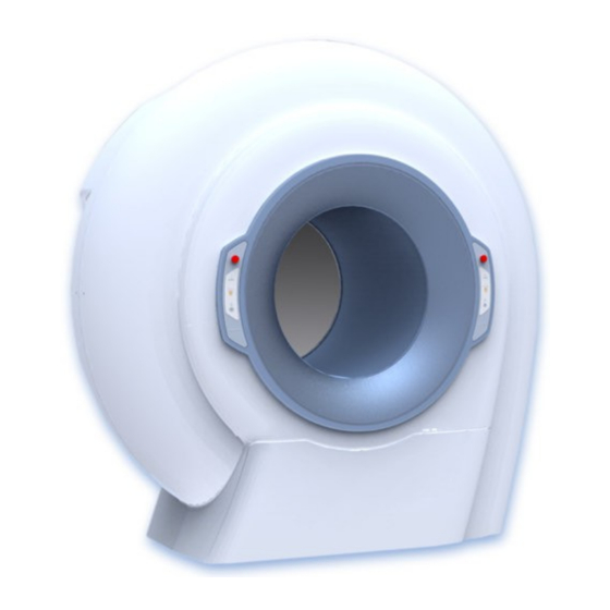
Page 32: Overall View
It is also possible to add more workstations for data processing and storage. For additional informational about this matter, please refer to the "NNT User Manual" document Figure 2: NewTom 5G complete system NOTE: The system may not be expanded with parts or... -
Page 33: Control Panels
ON by pushing the main switch located on the input panel. X-Ray emission indicator: 3 LEDs turn on simultaneously during the x-ray emission. Laser Button(L): Turns the positioning laser beam on/off. The laser will light up for about 60 seconds. NewTom 5G – User Manual... -
Page 34: Patient Table Console
ON to move the table to the default position. Use the P2 button also at the end of the scan to move the patient out of the gantry. NewTom 5G – User Manual... - Page 35 A red LED turns on in case of patient table fault condition. For more details about the use of patient table and complete available buttons and functions, please refer to the “Patient Table User Procedures” document. NewTom 5G – User Manual...
-
Page 36: Patient Table With Stretcher Console
P2 symbol (ie if the stretcher is completely out of the gantry with active limit switch). + / - + / - buttons The function depends on the current page displayed on the screen NewTom 5G – User Manual... - Page 37 A red LED is on when when an anomaly occurs. operator attention is required For more details about the use of patient table and complete available buttons and functions, please refer to the “Patient Table User Procedures” document. NewTom 5G – User Manual...
-
Page 38: Input Panel And Main Switch
The device is supplied with a few standard accessories: QA phantom: used for the execution of the Quality Assurance procedure. Calibration support: Plate to be used for the positioning of the QA phantom on the patient table. 4-10 NewTom 5G – User Manual... -
Page 39: Cables
Accessories, transducer and cables different from the ones here specified may change the electromagnetic compatibility characteristics of the device. 4.4.2 Optional accessories At the present time no optional accessories are available for a NewTom 5G system. NewTom 5G – User Manual 4-11... -
Page 40: System Start-Up
3. Turn off the scanner unit by pushing the main switch located on the input panel(left side of the device). WARNING: Turn off the device when it has not been used for longer than 3 hours. WARNING: Always turn the device off at the end of the working time. 4-12 NewTom 5G – User Manual... -
Page 41: Preliminary Procedures
The conditioning procedure is necessary in order to prepare the x-ray source for its routine working. It is compulsorily and automatically required by the NNT software every two weeks. Figure 7: Initial NNT screenshot with request of X-Ray Source Conditioning NewTom 5G – User Manual... - Page 42 Before launching the procedure, please verify that the scan area is completely free from objects. Figure 8: X-Ray Source conditioning process running At the end of conditioning process, the software will automatically run the Daily Check and Blank acquisition procedures. NewTom 5G – User Manual...
-
Page 43: Daily Check
By running the Daily Check procedure the system verifies that each part of itself properly works. Figure 9: Initial NNT screenshot with request of Daily check WARNING: Before launching the procedure, please verify that the scan area is completely free from objects. To that end, take out the patient table NewTom 5G – User Manual... -
Page 44: Blank Acquisition
Please carefully verify that no artifacts or objects appear. WARNING: Before launching the procedure, please verify that the scan area is completely free from objects. To that end, if not done previously, take out the patient table NewTom 5G – User Manual... -
Page 45: Invalidating The Blank Acquisition
To invalidate the blank acquisition select Scan Invalidate Blank from the main toolbar. At the next detector field selection the NNT software will ask a new blank acquisition. WARNING: If the test has been performed correctly but has not been completed successfully, please contact our Technical Support. NewTom 5G – User Manual... -
Page 46: Beam Limiter Test
The edges of the rectangle must be included between the two couples of red lines). Figure 11: Beam limiter test WARNING: If the grey image acquired is not correctly collimated within the red lines, please contact our Technical Support. NewTom 5G – User Manual... -
Page 47: Scanning
For children, we recommend using the lowest dose and fastest scanning mode available: ECO SCAN. FOV available only with the patient table with stretcher and software option enabled. “Enhanced Scan” option not available in case of eFOV scan NewTom 5G – User Manual... -
Page 48: Patient Scan
A special care has to be taken in case of children, elderly people, claustrophobic people, physically or mentally disabled. Proper breathing ✔ Ask the patient to breathe slowly during the scanning (a slow and continuous breath helps from swallowing). NewTom 5G – User Manual... - Page 49 Good examination times can be obtained also by carrying out all the preliminary procedures before starting the scan itself. Voice instructions ✔ Introduce the patient to possible voice instructions that the operator may give during the scan. NewTom 5G – User Manual...
-
Page 50: Positioning The Patient And Starting A New Scan
For more details about use of the patient table, please refer to the “Patient Table User Procedures” document. The guidelines for patient positioning during examination of the different anatomic regions are outlined in the attached document “General guidelines for the use of the NewTom 5G device in the dental and medical field”. WARNING:... - Page 51 Zone A: 35 Kg / 77 lbs Zone B: 90 Kg / 198 lbs Zone C: 175 Kg / 385 lbs 2) Sitting areas for adult patient (maximum weight 160Kg) 3) Distribution of maximum rated load 175kg (160kg + 15Kg accessories) NewTom 5G – User Manual...
-
Page 52: Patient Positioning With Patient Table
This task can be accomplished by pressing the P2 button on the table console. PATIENT TABLE DEFAULT POSITION 2) Help the patient to sit down on the table with the head resting on the head support. NewTom 5G – User Manual... - Page 53 In order to help the operator during the positioning of the patient, the laser can be turned on by pressing the LASER button on the scanner control panels or on the table console (required the NNT software to be open). NewTom 5G – User Manual...
- Page 54 Manual” document. 6) Once the scan process is finished, press the P2 button in order to slide out the table from the gantry, restore the default position and allow the patient to leave the room. NewTom 5G – User Manual...
-
Page 55: Patient Positioning With Patient Table With Stretcher
Make sure that the stretcher is completely out of the gantry and locked by the handle positioned at the side of the table console. Then, press P2 button on the table console. Figure 12: Patient table in facilitated uphill position NewTom 5G – User Manual... - Page 56 3) Press P1 button on the console by moving the patient table to “exam preparation” position. Figure 13: Patient table in exam preparation position 4) Unlock the stretcher and slide it into the gantry. Then relock the stretcher. Figure 14: Patient table with stretcher into the gantry 6-10 NewTom 5G – User Manual...
- Page 57 “Acquisition Operations with NewTom VGi-5G” document annex to the “NNT User Manual” document. 8) Once the scan process is finished, remove the patient from the gantry by sliding the stretcher completely out, then relock the stretcher. NewTom 5G – User Manual 6-11...
- Page 58 Figure 15: Patient table with stretcher out of the gantry Press P2 button in order to reset the patient table to the default position (facilitated uphill position) and allow the patient to leave the room. 6-12 NewTom 5G – User Manual...
-
Page 59: Scanning A Denture
6) Once the scan process is finished, remove the denture support from the table and press the P2 button in order to slide out the table from the gantry. 7) Place the patient head support on the on the table carbon fiber board. NewTom 5G – User Manual 6-13... -
Page 60: Denture Positioning With Patient Table With Stretcher
5) Insert the denture in the provided slit of the denture support, and position the support on the table carbon fiber board as shown in the following picture. Pay attention to do not reverse the denture (must be in the same position as in the patient mouth). 6-14 NewTom 5G – User Manual... - Page 61 P2 button in order to reset the patient table to the default position (facilitated uphill position) 9) Place the patient head support on the on the patient table carbon fiber board. NewTom 5G – User Manual 6-15...
-
Page 62: Quality Assurance
Remove the head support and move the table to the “exam preparation position” by pressing P1 button. Unlock the stretcher and slide it into the gantry. Then relock the stretcher. 3) Position the phantom support on the table carbon fiber board, then place the phantom on the support NewTom 5G – User Manual... - Page 63 (see next picture=. 5) For the phantom scan please refer to Par. “QA Phantom scan” and “Remote patient position adjustment” included in the “Acquisition Operations with NewTom VGi-5G” document annex to the “NNT User Manual” document. NewTom 5G – User Manual...
- Page 64 P2 button in order to reset the patient table to the default position (facilitated uphill position) 7) Place the patient head support on the table carbon fiber board. NewTom 5G – User Manual...
-
Page 65: Images Samples
7 Quality assurance 7.2 Images samples Hereafter some sample images from a QA phantom analysis. Lateral view Axial view Panoramic view NewTom 5G – User Manual... -
Page 66: Storage Of Qa Data
To move among the reports list use the PAGE DOWN, PAGE UP keyboard button. It is possible to save a copy of the QA report analysis in PDF format: select menu File Save as PDF. It is recommended to save a printed copy of each report. NewTom 5G – User Manual... -
Page 67: Troubleshooting
8 Troubleshooting Troubleshooting For the troubleshooting of the device please refer to the “NNT – Error Guide” document. NewTom 5G – User Manual... -
Page 68: Iec61223: Acceptance Test
Not applicable. Patient positioning accuracy [paragraph 5.2] ✔ The NewTom 5G is equipped with two cross shaped laser pointer aimed to help the patient positioning. The horizontal line identify the axial plane of the acquired volume, the vertical line identify the sagittal plane of the acquired volume. - Page 69 [8x8] 2.2 mGy 30% [15x5] HiRes 6.7 mGy 30% [12x8] HiRes 7.6 mGy 30% [8x8] HiRes 6.4 mGy 30% 4.6 mGy 30% [6x6] HiRes Loading factors: automatically selected by the software. Standard Dose, Regular Scan NewTom 5G – User Manual...
- Page 70 [8x8] 4.4 mGy 30% [15x5] HiRes 13.5 mGy 30% 15.3 mGy 30% [12x8] HiRes [8x8] HiRes 12.8 mGy 30% [6x6] HiRes 9.4 mGy 30% Loading factors: automatically selected by the software. Boosted Dose, Enhanced Scan NewTom 5G – User Manual...
- Page 71 < 85 [6x6] HiRes (ultra small voxel) < 220 Boosted Dose, Regular Scan [18x16] (standard voxel) < 30 [18x16] (ultra small voxel) < 45 [8x8] (standard voxel) < 25 [8x8] (ultra small voxel) < 50 NewTom 5G – User Manual...
- Page 72 [6x6] HiRes (standard voxel) < 70 [6x6] HiRes (ultra small voxel) < 40 Boosted Dose [18x16] (standard voxel) < 120 [18x16] (ultra small voxel) < 60 [8x8] (standard voxel) < 50 [8x8] (ultra small voxel) < 50 NewTom 5G – User Manual...
- Page 73 > 10 [18x16] (standard voxel) > 14 [15x22e] (standard voxel) > 13 [8x8] (standard voxel) > 14 (lp/cm) [15x5] HiRes (standard voxel) > 18 [12x8] HiRes (standard voxel) > 18 [6x6] HiRes (standard voxel) > 18 NewTom 5G – User Manual...
-
Page 74: Appendix A- Technical References
1500 mm / 59” Depth (max) 700 mm / 27.5” Height (max) 1400 mm / 55.1” (back rest in vertical position) Height (max seat) 770 mm / 30.3” Height (min seat) 560 mm / 22.0” NewTom 5G – User Manual 10-1... -
Page 75: Detector
300 Kg / 661.3 lbs Maximum load 175Kg / 385.8 lbs (160Kg patient + 15Kg accessories) 10.2 Detector Pixels 1920 x 1536 Pixels Pixel size 127 x 127 m Pixel depth Frame rate Max 10-2 NewTom 5G – User Manual... -
Page 76: Scout View Radiological Images
Pixel Size 0.127 x 0.127 [12x8] HiRes Image pixels 1140 x 1000 Pixels Pixel depth Pixel Size 0.127 x 0.127 [8x8] HiRes Image pixels 906 x 988 Pixels Pixel depth Pixel Size 0.127 x 0.127 NewTom 5G – User Manual 10-3... -
Page 77: Reconstructed Volume
Pixel depth [12x8] Shape Cylinder Reconstructed Volume Size Ø12 x H8 Voxel Size 0.300 0.250 0.200 0.150 Image pixels 410 x 410 492 x 492 614 x 614 820 x 820 Pixels Pixel depth 10-4 NewTom 5G – User Manual... - Page 78 Pixel depth [6x6] HiRes Shape Cylinder Reconstructed Volume Size Ø6 x H6 Voxel Size 0.150 0.125 0.100 0.075 Image pixels 410 x 410 492 x 492 614 x 614 672 x 672 Pixels Pixel depth NewTom 5G – User Manual 10-5...
-
Page 79: Radiological Parameters
10 APPENDIX A- Technical references 10.5 Radiological parameters 10.5.1 X-Ray Tube IAE model X22 0.3/0.6 10-6 NewTom 5G – User Manual... - Page 80 10 APPENDIX A- Technical references NewTom 5G – User Manual 10-7...
- Page 81 10 APPENDIX A- Technical references 10-8 NewTom 5G – User Manual...
- Page 82 10 APPENDIX A- Technical references NewTom 5G – User Manual 10-9...
- Page 83 10 APPENDIX A- Technical references 10-10 NewTom 5G – User Manual...
-
Page 84: X-Ray Tube Head
Nominal electrical power, 4s emission 2.2 kW Maximum power ripple < 1% Maximum power voltage rise time < 0.5 ms According to IEC60601-2-28, par. 6.8.2.b) According to IEC60601-2-7, par. 6.8.2 a) According to IEC60601-2-44, par. 6.8.2 a) NewTom 5G – User Manual 10-11... -
Page 85: X-Ray Source Assembly
According to IEC 60601-2-44:2009 par. 203.6.3.2 According to IEC 60601-2-7:1998 par. 50.104.1 According to IEC 60601-2-7:1998 par. 50.104.2 According to IEC 60601-2-7:1998 par. 50.105.4 According to IEC 60601-2-7:1998 par. 50.104.3 According to IEC 60601-2-7:1998 par. 50.104.3 10-12 NewTom 5G – User Manual... -
Page 86: Inverter
16 A Apparent supply resistance 0.14 ohm OUTPUTS Peak voltage 350 Vpk Peak current maximum 120 Apk Max. Waveform Sinusoidal 20 kHz PHYSICAL DATA Size 160 x 280 x 235 mm Weight 7 kg NewTom 5G – User Manual 10-13... -
Page 87: Dose Declaration
Eco Scan Std Dose: 110kV 25.30mAs - Reg. Scan Std Dose: 110kV 39.55mAs - Reg. Scan Boosted Dose: 110kV 71.25mAs - Enh. Scan Std Dose: 110kV 50.60mAs - Enh. Scan Boosted Dose: 110kV 93.27mAs 10-14 NewTom 5G – User Manual... - Page 88 Eco Scan Std Dose: 110kV 72.60mAs - Reg. Scan Std Dose: 110kV 108.90mAs - Enh. Scan Std Dose: 110kV 147.01mAs Loading factors: automaticamente impostati dal software Eco Scan Std Dose: 110kV 72.60mAs - Reg. Scan Std Dose: 110kV 89.84mAs - Enh. Scan Std Dose: 110kV 147.01mAs NewTom 5G – User Manual 10-15...
- Page 89 Eco Scan Std Dose: 110kV 72.60mAs - Reg. Scan Std Dose: 110kV 108.90mAs - Enh. Scan Std Dose: 110kV 147.01mAs Loading factors: automatically set by software Eco Scan Std Dose: 110kV 72.60mAs - Reg. Scan Std Dose: 110kV 89.84mAs - Enh. Scan Std Dose: 110kV 147.01mAs 10-16 NewTom 5G – User Manual...
- Page 90 Boosted Dose Standard Dose Boosted Dose [15x22e] 10,9 Loading factors: automaticamente impostati dal software Eco Scan Std Dose: 110kV 32,85mAs - Reg. Scan Std Dose: 110kV 48,84mAs - Reg. Scan Boosted Dose: 110kV 97,63mAs NewTom 5G – User Manual 10-17...
- Page 91 Eco Scan Std Dose: 110kV 72.60mAs - Reg. Scan Std Dose: 110kV 108.90mAs - Enh. Scan Std Dose: 110kV 147.01mAs Loading factors: automatically set by software Eco Scan Std Dose: 110kV 72.60mAs - Reg. Scan Std Dose: 110kV 89.84mAs - Enh. Scan Std Dose: 110kV 147.01mAs 10-18 NewTom 5G – User Manual...
- Page 92 Eco Scan Std Dose: 110kV 72.60mAs - Reg. Scan Std Dose: 110kV 108.90mAs - Enh. Scan Std Dose: 110kV 147.01mAs Loading factors: automatically set by software Eco Scan Std Dose: 110kV 72.60mAs - Reg. Scan Std Dose: 110kV 89.84mAs - Enh. Scan Std Dose: 110kV 147.01mAs NewTom 5G – User Manual 10-19...
- Page 93 10 APPENDIX A- Technical references Indication of the dose profiles Graphs calculated according to IEC 60601-2-44: 2009 Par. 203.110 Regular scan, Standard dose, 1.96mAs 3.6s 10-20 NewTom 5G – User Manual...
- Page 94 10 APPENDIX A- Technical references Regular scan, Standard dose, 1.96mAs 3.6s Regular scan, Standard dose, 2.94mAs 5.4s Date: 2012-06-20 NewTom 5G – User Manual 10-21...
-
Page 95: Stray Radiation Diagram
Figure I – Stray radiation (uGy/mAs) according to IEC 60601-2-44: 2009 Par. 203.13 (stray radiation on the vertical axis corresponds to the horizontal plane) 55 Measured by using “head phantom" according to IEC 60601-2-44: 2009 Par 203.108 10-22 NewTom 5G – User Manual... -
Page 96: Laser
Operating humidity: 10% ¸ 85 % (not condensing) Operating altitude: ≤ 3000m Over voltage category: Pollution degree: Transport and storage -20 ¸ +70 °C temperature: Transport and storage humidity: 10% ¸ 85 % (not condensing) NewTom 5G – User Manual 10-23... -
Page 97: Electromagnetic Compatibility
TABLE: Guidance and manufacturer's declaration - electromagnetic emissions The device NewTom 5G is intended for use in the electromagnetic environment specified below. The customer or the user of the device NewTom 5G should assure that is used in such an environment. Emission test... - Page 98 TABLE: Guidance and manufacturer's declaration - electromagnetic immunity The device NewTom 5G is intended for use in the electromagnetic environment specified below. The customer or the user of the device NewTom 5G should assure that is used in such an environment. Immunity test...
- Page 99 RF transmitters, an electromagnetic site survey should be performed. If the measured field strength in the location in which the NewTom 5G is used exceeds the RF compliance level above, the NewTom 5G should be observed to verify normal operation.
- Page 100 TABLE: Recommended separation distances between portable and mobile RF communications equipment and the equipment The device NewTom 5G is intended for use in the electromagnetic environment in which radiated RF disturbances are controlled. The customer or the user of the device NewTom 5G can help prevent...
-
Page 101: Essential Performance
10 APPENDIX A- Technical references All components, accessories, spare parts must be approved and supplied by CEFLA s.c. Particularly, the connection cables must be ONLY the ones described under Par. 4.4.1 - “Cables“. WARNING: Use of accessories, transducers, and cables other than those... -
Page 102: Appendix B - Security Standards
11 APPENDIX B – Security standards 11 APPENDIX B – Security standards The NewTom 5G equipment has been built in conformity with IEC normative regarding safety of electric- medical devices of similar typology and, particularly, with the normative: IEC 60601-1: 2005 + CORR. 1 (2006) + CORR. 2 (2007) - General requirements for basic safety •... -
Page 103: Appendix C - Labels
Rear plastic cover on the bottom left side IDENTIFICATION LABEL FOR CHINESE MARKET ✔ (only for devices intended for chinese market) Position: Rear plastic cover on the bottom left side, near the plate on scanner NewTom 5G – User Manual 12-1... - Page 104 X-RAY WHEN EQUIPMENT IN OPERATION UNAUTHORIZED USE IS STRICLY PROHIBITED AVERTISSEMENT RAYONS X - ATTENTION: PRESENCE RAYONS QUAND L'EQUIPEMENT FONCTIONNEMENT UTILISATION NON AUTORISÉE STRICTEMENT INTERDITE Position: Front plastic cover on the bottom left side. 12-2 NewTom 5G – User Manual...
- Page 105 Rear plastic cover on the bottom left side, next to the main switch. WARNING LABEL FOR DEVICES WITH LASER (NORMAL USE) ✔ Position: Rear plastic cover on the bottom left side on top of the scanner label. NewTom 5G – User Manual 12-3...
- Page 106 WARNING LABEL FOR LASER DEVICES (DISTANCE <40MM) ✔ Position: On the laser brackets next to the laser modules (1 for each laser). BEAM LIMITER GLOBAL LABEL ✔ CEFLA s.c. – Italy P/N 96600716 P/N 99934389 S/N ___________ Position: On the beam limiter lead collimator plate.
- Page 107 12 APPENDIX C - Labels BEAM LIMITER EQUIVALENT FILTER LABEL ✔ CEFLA s.c. – Italy Al - P/N 99934483 2 mm Al @ 75 kV Position: On the 2mm aluminum filter of the beam limiter. BEAM LIMITER EQUIVALENT MIRROR PLATE LABEL ✔...
- Page 108 On the main structure, next to the points with risk of hand crushing. FOLLOW INSTRUCTIONS FOR USE LABEL ✔ Position: Rear plastic cover on the bottom left side on top of the main switch and input fuse label STOP LABEL ✔ Position: Emergency buttons 12-6 NewTom 5G – User Manual...
- Page 109 State in which he practices to use or order the use of x-ray imaging systems. 21CFR801.109(b) Position: Rear plastic cover on the bottom left side on top of the main switch and input fuse label NewTom 5G – User Manual 12-7...
- Page 110 NEWTOM™ 5G is a commercial trademark of CEFLA s.c. All other products and brand names are registered trademarks or trademarks of their respective companies. NEWTOM™ 5G is manufactured by: CEFLA s.c. Phone: +39 045 8202727 Fax +39 045 8203040 e-mail: info@newtom.it...
Need help?
Do you have a question about the NewTom 5G and is the answer not in the manual?
Questions and answers